EP1595572B1 - Flachdrahtspiralenelektrode benutzbar in einschraubbaren Herzstimulationsleitungen - Google Patents
Flachdrahtspiralenelektrode benutzbar in einschraubbaren Herzstimulationsleitungen Download PDFInfo
- Publication number
- EP1595572B1 EP1595572B1 EP05252823A EP05252823A EP1595572B1 EP 1595572 B1 EP1595572 B1 EP 1595572B1 EP 05252823 A EP05252823 A EP 05252823A EP 05252823 A EP05252823 A EP 05252823A EP 1595572 B1 EP1595572 B1 EP 1595572B1
- Authority
- EP
- European Patent Office
- Prior art keywords
- lead
- electrode
- helix
- inches
- implantable
- Prior art date
- Legal status (The legal status is an assumption and is not a legal conclusion. Google has not performed a legal analysis and makes no representation as to the accuracy of the status listed.)
- Ceased
Links
Images


Classifications
-
- A—HUMAN NECESSITIES
- A61—MEDICAL OR VETERINARY SCIENCE; HYGIENE
- A61N—ELECTROTHERAPY; MAGNETOTHERAPY; RADIATION THERAPY; ULTRASOUND THERAPY
- A61N1/00—Electrotherapy; Circuits therefor
- A61N1/02—Details
- A61N1/04—Electrodes
- A61N1/05—Electrodes for implantation or insertion into the body, e.g. heart electrode
- A61N1/056—Transvascular endocardial electrode systems
- A61N1/057—Anchoring means; Means for fixing the head inside the heart
- A61N1/0573—Anchoring means; Means for fixing the head inside the heart chacterised by means penetrating the heart tissue, e.g. helix needle or hook
-
- A—HUMAN NECESSITIES
- A61—MEDICAL OR VETERINARY SCIENCE; HYGIENE
- A61N—ELECTROTHERAPY; MAGNETOTHERAPY; RADIATION THERAPY; ULTRASOUND THERAPY
- A61N1/00—Electrotherapy; Circuits therefor
- A61N1/02—Details
- A61N1/04—Electrodes
- A61N1/05—Electrodes for implantation or insertion into the body, e.g. heart electrode
- A61N1/056—Transvascular endocardial electrode systems
- A61N1/057—Anchoring means; Means for fixing the head inside the heart
- A61N2001/0578—Anchoring means; Means for fixing the head inside the heart having means for removal or extraction
Definitions
- the present invention relates generally to implantable stimulation leads for use with an implantable pulse generator such as a cardiac pacemaker or defibrillator and, more specifically, to such an implantable stimulation lead with the capability of selectively anchoring an electrically active helix electrode of improved design at a desired site when the lead is fixated in the heart.
- helix electrode may be capable of extension and retraction from the header by being directly connected to the connector pin / distal coil subassembly. Turning of the connector pin results in the extension or retraction of the helix electrode from the header.
- a thread/screw mechanism is required. The helix electrode is used as a threaded screw which turns against a thread post in the header. As the helix rotates, by turning of the connector pin, it engages the thread post, which in turn drives the helix into and out of the header.
- Leads are also known which employ a fixed extended electrically active helix electrode and the invention is applicable to such leads as well.
- the helix electrode of either fixed screw-in or extendable and retractable screw-in leads is made out of a round wire.
- the size of the wire should be small enough so as not to severely damage the heart tissue but thick enough to achieve good fixation while being visible under fluoroscopy.
- the outer diameter of the helix electrode should be sufficiently large to achieve a good and less traumatic fixation but not too small to core out the heart tissue.
- the appropriate range of the helix wire diameter is between about 0.25 mm to 0.33 mm [10 mils (0.010 inches) and 13 mils (0.013 inches)] and the outer diameter of the helix wire desirably ranges from about 1.0 mm to 1.8 mm [0.040 inches to 0.070 inches].
- the outer diameter of the helix and the helix wire diameter must be balanced in order to create a first class helix electrode.
- the helix wire size and outer diameter could be reduced to a certain extent.
- further reduction of the helix wire size or helix outer diameter would compromise the performance of the helix electrode in terms of electrode pacing threshold and helix visibility.
- the invention allows for more design options for the tip of a smaller lead without compromising helix performance.
- U.S. Patent No. 4,860,769 to Fogarty et al. which provides for an implantable defibrillator electrode including a flexible insulated guide terminating in a flexible distal portion which includes a conductive element and is of a predetermined configuration, such that it may be extended to a linear configuration by the application of a concentric or axial force and upon the termination of such force assumes the predetermined configuration.
- the conductive portion of the electrode may be a spiral of flat wire helically wound on a generally cylindrical, non-conductive stem.
- U.S. Patent No. 4,920,979 to Bullara discloses a circumneural electrode assembly including a supportive flexible and insulating matrix formed into two oppositely directed helical portions which are centrally joined, and have free outer ends.
- the helical portions extend circumferentially at least one full turn, and preferably about one-half additional turn, for a total extent in the range of 360 degrees to 720 degrees.
- a thin and flexible conductive ribbon preferably of surface-roughened platinum, is secured to the inner surface of one of the helical portions, and multiple electrodes can be provided on one or both portions.
- a connecting wire or cable extends from the electrode and matrix for coupling to an electronic package which is normally implanted elsewhere in the patient's body.
- U.S. Patent 5,551,427 to Altman discloses an implantable device for the elimination of an arrhythmogenic site from the myocardium.
- the device may be in the form of a conductive helix, which is permanently implantable into the heart wall around the arrhythmogenic site, deliverable by a catheter with a disengaging stylet.
- U.S. Patent No. 5,964,702 to Grill, Jr. et al. discloses a helical nerve cuff electrode which is provided for encircling a nerve trunk or other body tissue with at least one medication or electrically energy conductive member disposed along the length of the helical cuff.
- the cuff includes a self-curling sheet of non-conductive material laminations which are collectively self-biased to curl into a tight helix.
- An implantable endocardial lead for use with a cardiac stimulation device includes an internal electrical conductor and an active fixation electrode with a coaxial electrically active helix coupled to the distal end of the electrical conductor for effecting penetration into the myocardial tissue.
- the electrode is constructed of flat wire having a non-circular, such as quadrilateral or elliptical, cross section.
- the electrically active helix may be fixed or movable between a retracted position fully within the lead and an extended position advanced beyond the distal end of the lead.
- An insulation sheath of silicone or polyurethane covers the electrical conductor defining an internal chamber extending from the proximal end to the distal end and an electrical connector is coupled to the proximal end of the electrical conductor.
- the outer diameter of the electrode is in the range of about 1.0 mm to 3.0 mm [3 French (0.039 inches) to 9 French (0.118 inches)] and the cross sectional dimension of the electrode wire is greater in the direction of the longitudinal axis of the lead than in a direction transverse of the longitudinal axis of the lead, being in the range of about 0.05 mm X 0.20 mm to about 0.13 mm X 0.38 mm [0.002 inches X 0.008 inches to about 0.005 inches X 0.015 inches].
- flat wire with a thickness typically thinner than the diameter of the round wire, is used for the helix electrode. It could be used for smaller diameter helix electrodes while maintaining other critical design parameters and potentially increasing fluoroscopic visibility of the helix due to a wider profile of the flat wire as compared with the round, conventional, wire.
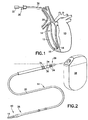
- FIG. 1 there is shown a diagrammatic perspective view partially cut away and shown in section of a heart 10 into the right ventricle 12 of which is inserted a body implantable lead 14 of the endocardial type according to one illustrative embodiment.
- a body implantable lead 14 of the endocardial type according to one illustrative embodiment.
- the lead 14 of an active fixation design is attached to an interior wall 16 of the heart 10 by means of a fixing helix 18 which engages the tissue or trabeculae of the heart.
- the lead 14 also includes an insulation sheath 20 interconnecting the helix 18 secured to the interior wall 16 and an electrical connector 24 at a proximal end 26 to which can be attached a cardiac stimulation device 28 such as a pacemaker or defibrillator (FIG. 2).
- a cardiac stimulation device 28 such as a pacemaker or defibrillator (FIG. 2).
- FIG. 1 a stylet 30 is illustrated inserted within the insulation sheath 20 and may be used to provide rigidity to the lead 14 during insertion of the lead into the heart 10.
- the elongated stylet 30 extends through a lumen of the insulation sheath 20 between a distal attachment device and a proximal manipulating device 32.
- the manipulating device is distant from the distal attachment device and may be a finger grip at a proximal extremity of the stylet 30 provided for controlling the introduction of the stylet into the lead 14 and its subsequent withdrawal.
- the lead 14 is designed for intravenous insertion and contact with the endocardium and, as such, may be conventionally referred to as an endocardial lead.
- the lead 14 includes coil or helically wound electrical conductors (not shown in this view) covered with the insulation sheath 20.
- the insulation sheath is preferably fabricated of silicone rubber, polyurethane or other suitable plastic material.
- the connector assembly 24 is provided with sealing rings 34 and carries at least one, and preferably a pair, of electrical contacts 36.
- the connector assembly 24 is constructed using known techniques and is preferably fabricated of silicone rubber, polyurethane or other suitable plastic material.
- Contacts 32 are preferably fabricated of stainless steel or other suitable electrically conductive material.
- the lead 20 is constructed to include a hollow interior extending from the proximal end 26 to a distal end 38. As earlier mentioned, the hollow interior of the lead 14 allows for the introduction of a stylet during implant, which is beneficial in allowing the surgeon to guide the otherwise flexible lead from the point of venous insertion to the myocardium.
- an electrode assembly 40 which may take many different forms.
- lead 14 may include one or more ring electrodes for bipolar sensing and pacing, as is well known in the art.
- Lead 14 may further include a defibrillation electrode for delivering defibrillation shocks.
- one or more conductors extend through the lead housing to conduct electrical energy to the various electrodes.
- the helix fixation member 18 may be electrically inactive, with the sensing and pacing functions being performed by the electrode assembly 40.
- FIGS. 3 and 4 depict a known construction for the distal end 38 of the lead 14 of FIG. 1.
- the helix or helical electrode 18 is seen affixed to an advanceable electrical interconnect 46.
- the electrical interconnect 46 is also electrically connected to the conductor 48 which extends from the distal end to the proximal end of the lead 14.
- the electrical interconnect 46 thus includes a tail portion 50, to which the conductor 48 is secured, a central shaft portion 52 and a head portion 54.
- the helical electrode 18 is connected to the head portion 54.
- the central shaft portion 52 of the electrical interconnect 46 passes through a seal assembly 56.
- the seal assembly 56 may include a pair of retaining rings 58 which cooperate to secure a resilient ring seal 60.
- the seal assembly 56 prevents bodily fluids from penetrating into the axial void extending through the center of the lead 14.
- the distal end 38 of the lead 14 terminates in a sleeve 62 which is essentially a cylindrical element having a central bore within which the helical electrode 18 is disposed and retractable.
- the sleeve 62 is preferably fabricated from a biocompatible elastomeric material.
- the distal tip of sleeve 62 may include one or more metallic rings 64, which are useful during implant to allow a physician to verify the position of the helical electrode 18 relative to the metallic ring 64 in either the extended or retracted position by the use of a fluoroscope.
- the sleeve 62 includes a knob 66 extending from the inner diameter to guide the rotative advancement of the helical electrode 18. It is to be understood that techniques for implanting a pacing lead and advancing the fixation elements are known in the art, and, therefore, will not be discussed here.
- the proximal end of the sleeve 62 is affixed to a stepped cylindrical element 68, which is preferably formed from a biocompatible nonconductive material.
- the stepped cylindrical element 68 includes a cylindrical portion 70 which slides into the proximal end of the cylindrical sleeve 62 and is bonded thereto.
- the seal assembly 56 is located between an end-face 72 of the stepped cylindrical element 68 and an internal step 74 of the sleeve 62.
- the proximal end of the distal assembly 36 may include a second ring electrode or sensor electrode 76 spaced proximally of the distal tip.
- the ring electrode 76 is electrically interconnected to a second conductor 78 which also extends from the proximal to the distal end of the lead body 22 and is helically wrapped about the cylindrical insulation containing the first conductor 48.
- the second electrical conductor 78 is also preferably encased in an insulation sleeve 80.
- the second electrical conductor 78 extends to and interconnects with an electrical contact (not shown) located at the connector assembly 28 at the proximal end 26 of the lead 14.
- a therapeutic delivery means which includes a therapeutic bullet 82 centrally disposed with respect to the helical electrode 18, that is, along the axis of the helix.
- the therapeutic bullet 82 is preferably secured to the head portion 54 of the electrical interconnect 46, and advanceable therewith. As depicted in FIG. 4, when the helical electrode 18 is fully extended and inserted into the myocardium upon implant, the therapeutic bullet 82 does not extend out of the end of the sleeve 62 as does the helical electrode 18.
- the therapeutic bullet 82 is only advanceable with the advancement of the electrical interconnect 46, other constructions are known according to which the therapeutic bullet is independently advanceable.
- FIGS. 5-9 show illustrative embodiments of a lead.
- the distal end 38 of the lead 14 is clearly seen in FIGS. 5-7.
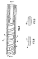
- FIGS. 5 and 6 illustrate a modified electrically active helical electrode 18A in its retracted position and FIG. 7 illustrates the electrode 18A in its extended position.
- the electrode 18A is constructed of flat wire having a non-circular cross section and, more specifically, is constructed of flat wire 84 having a quadrilateral cross section.
- This cross section of the electrode 18A is most clearly seen in FIG. 8 and it will be appreciated that the cross sectional dimension of the electrode wire is greater in the direction of the longitudinal axis of the lead 14 than in a direction transverse of that longitudinal axis.
- the outer diameter of the electrode 18A is in a distinctly superior range of about 1.0 mm to 3.0 mm [3 Fr to 9 Fr]. Because of the wider profile of the flat wire, its visibility under fluoroscopy is much improved over electrodes using wire of round cross section. Additionally, when such an electrode is used, distinct edges 86 of the flat wire 84 provide an improved pacing threshold due to edging effect.
- preferred cross sectional dimensions of the electrode wire 84 are in the range of 0.05 mm X 0.20 mm to about 0.13 mm X 0.38 mm [0.002 inches X 0.008 inches to about 0.005 inches X 0.015 inches].
- a further modified electrode may be constructed of flat wire 88 having an elliptical cross section.
Landscapes
- Health & Medical Sciences (AREA)
- Cardiology (AREA)
- Heart & Thoracic Surgery (AREA)
- Vascular Medicine (AREA)
- Engineering & Computer Science (AREA)
- Biomedical Technology (AREA)
- Nuclear Medicine, Radiotherapy & Molecular Imaging (AREA)
- Radiology & Medical Imaging (AREA)
- Life Sciences & Earth Sciences (AREA)
- Animal Behavior & Ethology (AREA)
- General Health & Medical Sciences (AREA)
- Public Health (AREA)
- Veterinary Medicine (AREA)
- Electrotherapy Devices (AREA)
Claims (7)
- Implantierbare endokardische Führung (14) mit einer longitudinalen Achse, welche sich zwischen proximalen und distalen Enden (26, 38) erstreckt, die implantierbare endokardische Führung ist für die Benutzung mit einer Herz-Stimulations-Einrichtung (28) und umfasst: einen elektrischen Leiter (48) innerhalb der Führung, welcher sich sich zwischen proximalen und distalen Enden (26, 38) erstreckt; und eine aktive Befestigungselektrode, welche eine elektrisch aktive Spirale (18A) koaxial zur endokardischen Führung (14) umfasst und mit dem distalen Ende (38) des elektrischen Leiters verbunden ist, die Elektrode ist aus Flachdraht gebildet mit einem nicht-kreisförmigen Querschnitt,
gekennzeichnet durch eine derartige Elektrode, dass das Maß des Querschnitts des Elektrodendrahtes (84) in der Richtung der longitudinalen Achse der Führung größer ist als in einer Richtung quer zur longitudinalen Achse der Führung. - Implantierbare endokardische Führung (14) nach Anspruch 1, wobei die Elektrode aus Flachdraht gebildet ist mit einem vierseitigen Querschnitt oder einem elliptischen Querschnitt.
- Implantierbare endokardische Führung (14) nach Anspruch 1 oder 2, wobei die elektrisch aktive Spirale (18A) zwischen einer voll innerhalb der Führung eingezogenen Position und einer jenseits aus dem distalen Ende (38) der Führung ausgefahrenen Position fixiert oder beweglich ist.
- Implantierbare endokardische Führung (14) nach einem der vorangehenden Ansprüche, umfassend: einen Isoliermantel (20), welcher den elektrischen Leiter (48) ummantelt und eine innenliegende Kammer definiert, welche sich von dem proximalen Ende (26) zu dem distalen Enden (38) erstreckt; und einen elektrischen Anschluss (24), welcher mit dem proximalen Ende (26) des elektrischen Leiters (48) verbunden ist.
- Implantierbare endokardische Führung (14) nach einem der vorangehenden Ansprüche, wobei der äußere Durchmesser der Elektrode im Bereich von 1 mm bis 3 mm [3 fr bis 9 fr] liegt.
- Implantierbare endokardische Führung (14) nach einem der vorangehenden Ansprüche, wobei die Querschnitts-Abmessungen des Elektrodendrahtes (84) im Bereich von ungefähr 0,05 mm x 0,20 mm bis ungefähr 0,13 mm x 0,38 mm [0,002 inch x 0,008 inch bis ungefähr 0,005 inch x 0,015 inch] liegt.
- Implantierbare endokardische Führung (14) nach einem der vorangehenden Ansprüche, wobei der Isoliermantel (20) aus zumindest Silikon und Polyurethan besteht.
Applications Claiming Priority (2)
| Application Number | Priority Date | Filing Date | Title |
|---|---|---|---|
| US10/842,888 US7162310B2 (en) | 2004-05-10 | 2004-05-10 | Flat wire helix electrode used in screw-in cardiac stimulation leads |
| US842888 | 2004-05-10 |
Publications (2)
| Publication Number | Publication Date |
|---|---|
| EP1595572A1 EP1595572A1 (de) | 2005-11-16 |
| EP1595572B1 true EP1595572B1 (de) | 2007-08-29 |
Family
ID=34941194
Family Applications (1)
| Application Number | Title | Priority Date | Filing Date |
|---|---|---|---|
| EP05252823A Ceased EP1595572B1 (de) | 2004-05-10 | 2005-05-09 | Flachdrahtspiralenelektrode benutzbar in einschraubbaren Herzstimulationsleitungen |
Country Status (3)
| Country | Link |
|---|---|
| US (1) | US7162310B2 (de) |
| EP (1) | EP1595572B1 (de) |
| DE (1) | DE602005002182T2 (de) |
Families Citing this family (59)
| Publication number | Priority date | Publication date | Assignee | Title |
|---|---|---|---|---|
| WO2006045075A1 (en) | 2004-10-20 | 2006-04-27 | Boston Scientific Limited | Leadless cardiac stimulation systems |
| US7532933B2 (en) | 2004-10-20 | 2009-05-12 | Boston Scientific Scimed, Inc. | Leadless cardiac stimulation systems |
| US7650186B2 (en) | 2004-10-20 | 2010-01-19 | Boston Scientific Scimed, Inc. | Leadless cardiac stimulation systems |
| US7983764B2 (en) * | 2005-08-12 | 2011-07-19 | Cardiac Pacemakers, Inc. | Co-radial lead with extendable/retractable fixation mechanism and apparatus therefor |
| JP2009518115A (ja) | 2005-12-09 | 2009-05-07 | ボストン サイエンティフィック サイムド,インコーポレイテッド | 心刺激システム |
| US8050774B2 (en) | 2005-12-22 | 2011-11-01 | Boston Scientific Scimed, Inc. | Electrode apparatus, systems and methods |
| US7657325B2 (en) * | 2005-12-30 | 2010-02-02 | Medtronic, Inc. | Implantable medical lead including a helical fixation member |
| US8099177B2 (en) * | 2006-03-02 | 2012-01-17 | St. Jude Medical Ab | Implantable medical lead and method for the manufacture thereof |
| US7937161B2 (en) | 2006-03-31 | 2011-05-03 | Boston Scientific Scimed, Inc. | Cardiac stimulation electrodes, delivery devices, and implantation configurations |
| US7840281B2 (en) | 2006-07-21 | 2010-11-23 | Boston Scientific Scimed, Inc. | Delivery of cardiac stimulation devices |
| US8290600B2 (en) | 2006-07-21 | 2012-10-16 | Boston Scientific Scimed, Inc. | Electrical stimulation of body tissue using interconnected electrode assemblies |
| US8644934B2 (en) | 2006-09-13 | 2014-02-04 | Boston Scientific Scimed Inc. | Cardiac stimulation using leadless electrode assemblies |
| US20080294229A1 (en) * | 2006-10-17 | 2008-11-27 | Friedman Paul A | Helical Electrodes for Intramyocardial Pacing and Sensing |
| US20100042189A1 (en) * | 2006-10-24 | 2010-02-18 | Per Jarl | Connecting device and method for manufacturing the same |
| US9427573B2 (en) * | 2007-07-10 | 2016-08-30 | Astora Women's Health, Llc | Deployable electrode lead anchor |
| EP2217321A4 (de) * | 2007-11-29 | 2011-06-29 | St Jude Medical | Aktives fixierungselement |
| US8738147B2 (en) | 2008-02-07 | 2014-05-27 | Cardiac Pacemakers, Inc. | Wireless tissue electrostimulation |
| WO2009129313A2 (en) | 2008-04-15 | 2009-10-22 | Cardiac Pacemakers, Inc. | Bundle of his stimulation system |
| US8600518B2 (en) | 2008-04-30 | 2013-12-03 | Boston Scientific Neuromodulation Corporation | Electrodes for stimulation leads and methods of manufacture and use |
| US8108054B2 (en) | 2009-02-04 | 2012-01-31 | Pacesetter, Inc. | Active fixation implantable medical lead configured to indicate via fluoroscopy embedment of helical anchor in cardiac tissue |
| US8543224B2 (en) * | 2009-06-30 | 2013-09-24 | Cardiac Pacemakers, Inc. | Active fixation lead with helix securement mechanism |
| EP2473228B1 (de) | 2009-09-03 | 2014-12-31 | Mayo Foundation For Medical Education And Research | Schrittmacher-, sensor- oder defibrillatorleitungen zur implantation in den herzmuskel |
| US8812134B2 (en) * | 2009-11-12 | 2014-08-19 | Cardiac Pacemakers Inc. | Helix fixation mechanism |
| EP2394695B1 (de) * | 2010-06-14 | 2012-09-26 | Sorin CRM SAS | Autonome intrakardiale Kapsel, und entsprechendes Implantationszubehör |
| EP2663360A1 (de) | 2011-01-14 | 2013-11-20 | Cardiac Pacemakers, Inc. | Implantierbare elektrode mit aktiver fixierung mit biologisch abbaubarer schraubenförmiger spitze |
| WO2013016203A1 (en) * | 2011-07-22 | 2013-01-31 | Boston Scientific Scimed, Inc. | Nerve modulation system with a nerve modulation element positionable in a helical guide |
| WO2013027107A1 (en) * | 2011-08-23 | 2013-02-28 | Simcha Milo | Device for creating temporary access and then closure |
| WO2013096873A1 (en) | 2011-12-22 | 2013-06-27 | Modular Bionics Inc. | Neural interface device and insertion tools |
| WO2014000231A1 (en) | 2012-06-28 | 2014-01-03 | Shanghai Microport Medical (Group) Co., Ltd. | Active cardiac electrical lead |
| EP2943132B1 (de) * | 2013-01-09 | 2018-03-28 | 4Tech Inc. | Weichgewebeanker |
| US10071243B2 (en) | 2013-07-31 | 2018-09-11 | Medtronic, Inc. | Fixation for implantable medical devices |
| US10842993B2 (en) | 2013-08-16 | 2020-11-24 | Cardiac Pacemakers, Inc. | Leadless cardiac pacing devices |
| WO2015023474A1 (en) | 2013-08-16 | 2015-02-19 | Cardiac Pacemakers, Inc. | Leadless cardiac pacemaker and retrieval device |
| US9492674B2 (en) | 2013-08-16 | 2016-11-15 | Cardiac Pacemakers, Inc. | Leadless cardiac pacemaker with delivery and/or retrieval features |
| US9393427B2 (en) | 2013-08-16 | 2016-07-19 | Cardiac Pacemakers, Inc. | Leadless cardiac pacemaker with delivery and/or retrieval features |
| EP3033146B1 (de) | 2013-08-16 | 2018-03-07 | Cardiac Pacemakers, Inc. | Abgabevorrichtungen für elektrodenlose herzvorrichtungen |
| US9480850B2 (en) | 2013-08-16 | 2016-11-01 | Cardiac Pacemakers, Inc. | Leadless cardiac pacemaker and retrieval device |
| CN105916544B (zh) | 2013-08-16 | 2019-11-12 | 心脏起搏器股份公司 | 无引线心脏起搏设备 |
| US10722723B2 (en) | 2013-08-16 | 2020-07-28 | Cardiac Pacemakers, Inc. | Delivery devices and methods for leadless cardiac devices |
| WO2015168155A1 (en) | 2014-04-29 | 2015-11-05 | Cardiac Pacemakers, Inc. | Leadless cardiac pacemaker with retrieval features |
| US10080887B2 (en) | 2014-04-29 | 2018-09-25 | Cardiac Pacemakers, Inc. | Leadless cardiac pacing devices including tissue engagement verification |
| US10674914B1 (en) | 2015-06-24 | 2020-06-09 | Modular Bionics Inc. | Wireless neural interface system |
| US11471672B2 (en) * | 2015-09-08 | 2022-10-18 | Case Western Reserve University | Neural electrodes and methods for implanting same |
| US20170189674A1 (en) * | 2016-01-04 | 2017-07-06 | Medtronic, Inc. | Medical electrical lead |
| US10463853B2 (en) | 2016-01-21 | 2019-11-05 | Medtronic, Inc. | Interventional medical systems |
| US10099050B2 (en) | 2016-01-21 | 2018-10-16 | Medtronic, Inc. | Interventional medical devices, device systems, and fixation components thereof |
| US10086192B2 (en) | 2016-07-07 | 2018-10-02 | Modular Bionics Inc. | Neural interface insertion and retraction tools |
| WO2018089311A1 (en) | 2016-11-08 | 2018-05-17 | Cardiac Pacemakers, Inc | Implantable medical device for atrial deployment |
| US12403306B2 (en) | 2017-10-23 | 2025-09-02 | Cardiac Pacemakers, Inc. | Electric field shaping leads for treatment of cancer |
| US11065439B1 (en) | 2017-12-11 | 2021-07-20 | Modular Bionics Inc. | Conforming modular neural interface system |
| EP3723624B8 (de) | 2017-12-14 | 2023-11-29 | Meacor, Inc. | Schraubenförmiges ankerantriebssystem |
| US11759632B2 (en) | 2019-03-28 | 2023-09-19 | Medtronic, Inc. | Fixation components for implantable medical devices |
| EP4480526A3 (de) | 2019-04-22 | 2025-03-12 | Boston Scientific Scimed, Inc. | Elektrische und chemotherapeutische kombinationsbehandlung von krebs |
| EP3958954B1 (de) | 2019-04-22 | 2024-04-24 | Boston Scientific Scimed Inc. | Vorrichtungen zur elektrischen stimulation zur krebsbehandlung |
| WO2020219517A2 (en) | 2019-04-23 | 2020-10-29 | Boston Scientific Scimed, Inc. | Electrical stimulation for cancer treatment with internal and external electrodes |
| CN113766950A (zh) | 2019-04-23 | 2021-12-07 | 波士顿科学国际有限公司 | 带有热治疗或热监测的电刺激 |
| US11883655B2 (en) | 2020-02-24 | 2024-01-30 | Boston Scientific Scimed, Inc. | Systems and methods for treatment of pancreatic cancer |
| US12508398B2 (en) | 2020-09-25 | 2025-12-30 | Greatbatch Ltd. | Medical device including shaft with flat wire coil |
| US20240175142A1 (en) * | 2022-11-25 | 2024-05-30 | Timothy David Stoltenburg | Helix Electrode For Impressed Current Cathodic Protection |
Family Cites Families (13)
| Publication number | Priority date | Publication date | Assignee | Title |
|---|---|---|---|---|
| IT1147750B (it) * | 1980-06-19 | 1986-11-26 | Sorin Biomedica Spa | Elettrodo per stimolatori cardiaci |
| DE8211641U1 (de) | 1982-04-22 | 1985-09-12 | Siemens AG, 1000 Berlin und 8000 München | Mehrpolige koaxiale Leitung |
| DE8211625U1 (de) | 1982-04-22 | 1985-09-12 | Siemens AG, 1000 Berlin und 8000 München | Mehrpolige elektrische Leitung |
| US4860769A (en) | 1987-11-12 | 1989-08-29 | Thomas J. Fogarty | Implantable defibrillation electrode |
| US4920979A (en) | 1988-10-12 | 1990-05-01 | Huntington Medical Research Institute | Bidirectional helical electrode for nerve stimulation |
| US5156151A (en) * | 1991-02-15 | 1992-10-20 | Cardiac Pathways Corporation | Endocardial mapping and ablation system and catheter probe |
| US5300108A (en) * | 1993-01-05 | 1994-04-05 | Telectronics Pacing Systems, Inc. | Active fixation lead with a dual-pitch, free spinning compound screw |
| US5354327A (en) * | 1993-04-07 | 1994-10-11 | Medtronic, Inc. | Conductor coil with specific ratio of torque to bending stiffness |
| US5505201A (en) | 1994-04-20 | 1996-04-09 | Case Western Reserve University | Implantable helical spiral cuff electrode |
| US5522875A (en) | 1994-07-28 | 1996-06-04 | Medtronic, Inc. | Medical electrical lead system having a torque transfer stylet |
| US5551427A (en) | 1995-02-13 | 1996-09-03 | Altman; Peter A. | Implantable device for the effective elimination of cardiac arrhythmogenic sites |
| US5545201A (en) | 1995-03-29 | 1996-08-13 | Pacesetter, Inc. | Bipolar active fixation lead for sensing and pacing the heart |
| US6687550B1 (en) | 2001-06-01 | 2004-02-03 | Pacesetter, Inc. | Active fixation electrode lead having an electrical coupling mechanism |
-
2004
- 2004-05-10 US US10/842,888 patent/US7162310B2/en not_active Expired - Fee Related
-
2005
- 2005-05-09 DE DE602005002182T patent/DE602005002182T2/de not_active Expired - Lifetime
- 2005-05-09 EP EP05252823A patent/EP1595572B1/de not_active Ceased
Also Published As
| Publication number | Publication date |
|---|---|
| US7162310B2 (en) | 2007-01-09 |
| US20050251240A1 (en) | 2005-11-10 |
| DE602005002182T2 (de) | 2008-05-21 |
| EP1595572A1 (de) | 2005-11-16 |
| DE602005002182D1 (de) | 2007-10-11 |
Similar Documents
| Publication | Publication Date | Title |
|---|---|---|
| EP1595572B1 (de) | Flachdrahtspiralenelektrode benutzbar in einschraubbaren Herzstimulationsleitungen | |
| EP2674192B1 (de) | Medizinische implantierbare Leitung mit doppelter Helix | |
| US5342414A (en) | Transvenous defibrillation lead | |
| JP2838500B2 (ja) | 人体植え込み型の医療用電気リード | |
| US5246014A (en) | Implantable lead system | |
| US4146036A (en) | Body-implantable lead with protector for tissue securing means | |
| US5716390A (en) | Reduced diameter active fixation pacing lead using concentric interleaved coils | |
| US5800496A (en) | Medical electrical lead having a crush resistant lead body | |
| EP2526997B1 (de) | Stimulationssystem für His-Bündel | |
| EP0979123B1 (de) | Intrakardiales defibrillierungssystem | |
| US6493591B1 (en) | Implantable active fixation lead with guidewire tip | |
| EP2340869B1 (de) | Befestigungshelix und multipolare medizinische Elektrode | |
| US6973352B1 (en) | Steerable cardiac pacing and sensing catheter and guidewire for implanting leads | |
| US8954168B2 (en) | Implantable device lead including a distal electrode assembly with a coiled component | |
| US7711437B1 (en) | Lead fixation device | |
| US8150536B2 (en) | Low profile active fixation cardiac lead having torque transmitting means | |
| WO2005107851A1 (en) | Novel lead body assemblies | |
| US6819959B1 (en) | Extendable/retractable screw-in tip design with an improved thread/screw mechanism | |
| WO2012096714A1 (en) | Implantable active fixation lead with biodegradable helical tip | |
| US7379776B1 (en) | Stylet design | |
| US20140114387A1 (en) | Chatter-free active fixation lead |
Legal Events
| Date | Code | Title | Description |
|---|---|---|---|
| PUAI | Public reference made under article 153(3) epc to a published international application that has entered the european phase |
Free format text: ORIGINAL CODE: 0009012 |
|
| AK | Designated contracting states |
Kind code of ref document: A1 Designated state(s): AT BE BG CH CY CZ DE DK EE ES FI FR GB GR HU IE IS IT LI LT LU MC NL PL PT RO SE SI SK TR |
|
| AX | Request for extension of the european patent |
Extension state: AL BA HR LV MK YU |
|
| 17P | Request for examination filed |
Effective date: 20060516 |
|
| AKX | Designation fees paid |
Designated state(s): CH DE FR IE IT LI |
|
| 17Q | First examination report despatched |
Effective date: 20060804 |
|
| GRAP | Despatch of communication of intention to grant a patent |
Free format text: ORIGINAL CODE: EPIDOSNIGR1 |
|
| RAP1 | Party data changed (applicant data changed or rights of an application transferred) |
Owner name: PACESETTER, INC. |
|
| GRAS | Grant fee paid |
Free format text: ORIGINAL CODE: EPIDOSNIGR3 |
|
| GRAA | (expected) grant |
Free format text: ORIGINAL CODE: 0009210 |
|
| AK | Designated contracting states |
Kind code of ref document: B1 Designated state(s): CH DE FR IE IT LI |
|
| REG | Reference to a national code |
Ref country code: CH Ref legal event code: EP |
|
| REG | Reference to a national code |
Ref country code: IE Ref legal event code: FG4D |
|
| REF | Corresponds to: |
Ref document number: 602005002182 Country of ref document: DE Date of ref document: 20071011 Kind code of ref document: P |
|
| REG | Reference to a national code |
Ref country code: CH Ref legal event code: NV Representative=s name: KIRKER & CIE S.A. |
|
| ET | Fr: translation filed | ||
| PLBE | No opposition filed within time limit |
Free format text: ORIGINAL CODE: 0009261 |
|
| STAA | Information on the status of an ep patent application or granted ep patent |
Free format text: STATUS: NO OPPOSITION FILED WITHIN TIME LIMIT |
|
| 26N | No opposition filed |
Effective date: 20080530 |
|
| PG25 | Lapsed in a contracting state [announced via postgrant information from national office to epo] |
Ref country code: IE Free format text: LAPSE BECAUSE OF NON-PAYMENT OF DUE FEES Effective date: 20080509 |
|
| REG | Reference to a national code |
Ref country code: FR Ref legal event code: PLFP Year of fee payment: 12 |
|
| REG | Reference to a national code |
Ref country code: FR Ref legal event code: PLFP Year of fee payment: 13 |
|
| REG | Reference to a national code |
Ref country code: FR Ref legal event code: PLFP Year of fee payment: 14 |
|
| PGFP | Annual fee paid to national office [announced via postgrant information from national office to epo] |
Ref country code: DE Payment date: 20190412 Year of fee payment: 15 Ref country code: IT Payment date: 20190523 Year of fee payment: 15 |
|
| PGFP | Annual fee paid to national office [announced via postgrant information from national office to epo] |
Ref country code: FR Payment date: 20190417 Year of fee payment: 15 |
|
| PGFP | Annual fee paid to national office [announced via postgrant information from national office to epo] |
Ref country code: CH Payment date: 20190425 Year of fee payment: 15 |
|
| REG | Reference to a national code |
Ref country code: DE Ref legal event code: R119 Ref document number: 602005002182 Country of ref document: DE |
|
| PG25 | Lapsed in a contracting state [announced via postgrant information from national office to epo] |
Ref country code: LI Free format text: LAPSE BECAUSE OF NON-PAYMENT OF DUE FEES Effective date: 20200531 Ref country code: CH Free format text: LAPSE BECAUSE OF NON-PAYMENT OF DUE FEES Effective date: 20200531 |
|
| PG25 | Lapsed in a contracting state [announced via postgrant information from national office to epo] |
Ref country code: FR Free format text: LAPSE BECAUSE OF NON-PAYMENT OF DUE FEES Effective date: 20200531 |
|
| PG25 | Lapsed in a contracting state [announced via postgrant information from national office to epo] |
Ref country code: DE Free format text: LAPSE BECAUSE OF NON-PAYMENT OF DUE FEES Effective date: 20201201 |
|
| PG25 | Lapsed in a contracting state [announced via postgrant information from national office to epo] |
Ref country code: IT Free format text: LAPSE BECAUSE OF NON-PAYMENT OF DUE FEES Effective date: 20200509 |
|
| P01 | Opt-out of the competence of the unified patent court (upc) registered |
Effective date: 20230616 |