EP1595630A1 - Gehrungssäge mit Winkeleinstellung - Google Patents
Gehrungssäge mit Winkeleinstellung Download PDFInfo
- Publication number
- EP1595630A1 EP1595630A1 EP20040010504 EP04010504A EP1595630A1 EP 1595630 A1 EP1595630 A1 EP 1595630A1 EP 20040010504 EP20040010504 EP 20040010504 EP 04010504 A EP04010504 A EP 04010504A EP 1595630 A1 EP1595630 A1 EP 1595630A1
- Authority
- EP
- European Patent Office
- Prior art keywords
- turntable
- miter saw
- fixing device
- base
- locking means
- Prior art date
- Legal status (The legal status is an assumption and is not a legal conclusion. Google has not performed a legal analysis and makes no representation as to the accuracy of the status listed.)
- Granted
Links
Images

Classifications
-
- B—PERFORMING OPERATIONS; TRANSPORTING
- B27—WORKING OR PRESERVING WOOD OR SIMILAR MATERIAL; NAILING OR STAPLING MACHINES IN GENERAL
- B27G—ACCESSORY MACHINES OR APPARATUS FOR WORKING WOOD OR SIMILAR MATERIALS; TOOLS FOR WORKING WOOD OR SIMILAR MATERIALS; SAFETY DEVICES FOR WOOD WORKING MACHINES OR TOOLS
- B27G5/00—Machines or devices for working mitre joints with even abutting ends
- B27G5/02—Machines or devices for working mitre joints with even abutting ends for sawing mitre joints; Mitre boxes
-
- B—PERFORMING OPERATIONS; TRANSPORTING
- B23—MACHINE TOOLS; METAL-WORKING NOT OTHERWISE PROVIDED FOR
- B23D—PLANING; SLOTTING; SHEARING; BROACHING; SAWING; FILING; SCRAPING; LIKE OPERATIONS FOR WORKING METAL BY REMOVING MATERIAL, NOT OTHERWISE PROVIDED FOR
- B23D47/00—Sawing machines or sawing devices working with circular saw blades, characterised only by constructional features of particular parts
- B23D47/02—Sawing machines or sawing devices working with circular saw blades, characterised only by constructional features of particular parts of frames; of guiding arrangements for work-table or saw-carrier
- B23D47/025—Sawing machines or sawing devices working with circular saw blades, characterised only by constructional features of particular parts of frames; of guiding arrangements for work-table or saw-carrier of tables
-
- B—PERFORMING OPERATIONS; TRANSPORTING
- B23—MACHINE TOOLS; METAL-WORKING NOT OTHERWISE PROVIDED FOR
- B23D—PLANING; SLOTTING; SHEARING; BROACHING; SAWING; FILING; SCRAPING; LIKE OPERATIONS FOR WORKING METAL BY REMOVING MATERIAL, NOT OTHERWISE PROVIDED FOR
- B23D47/00—Sawing machines or sawing devices working with circular saw blades, characterised only by constructional features of particular parts
- B23D47/132—Sawing machines or sawing devices working with circular saw blades, characterised only by constructional features of particular parts of means to position the saw blade at a specified angle when adjusting about an axis perpendicular to the work support surface
-
- B—PERFORMING OPERATIONS; TRANSPORTING
- B23—MACHINE TOOLS; METAL-WORKING NOT OTHERWISE PROVIDED FOR
- B23Q—DETAILS, COMPONENTS, OR ACCESSORIES FOR MACHINE TOOLS, e.g. ARRANGEMENTS FOR COPYING OR CONTROLLING; MACHINE TOOLS IN GENERAL CHARACTERISED BY THE CONSTRUCTION OF PARTICULAR DETAILS OR COMPONENTS; COMBINATIONS OR ASSOCIATIONS OF METAL-WORKING MACHINES, NOT DIRECTED TO A PARTICULAR RESULT
- B23Q16/00—Equipment for precise positioning of tool or work into particular locations not otherwise provided for
- B23Q16/02—Indexing equipment
- B23Q16/04—Indexing equipment having intermediate members, e.g. pawls, for locking the relatively movable parts in the indexed position
- B23Q16/06—Rotary indexing
- B23Q16/065—Rotary indexing with a continuous drive
-
- B—PERFORMING OPERATIONS; TRANSPORTING
- B27—WORKING OR PRESERVING WOOD OR SIMILAR MATERIAL; NAILING OR STAPLING MACHINES IN GENERAL
- B27B—SAWS FOR WOOD OR SIMILAR MATERIAL; COMPONENTS OR ACCESSORIES THEREFOR
- B27B5/00—Sawing machines working with circular or cylindrical saw blades; Components or equipment therefor
- B27B5/29—Details; Component parts; Accessories
-
- Y—GENERAL TAGGING OF NEW TECHNOLOGICAL DEVELOPMENTS; GENERAL TAGGING OF CROSS-SECTIONAL TECHNOLOGIES SPANNING OVER SEVERAL SECTIONS OF THE IPC; TECHNICAL SUBJECTS COVERED BY FORMER USPC CROSS-REFERENCE ART COLLECTIONS [XRACs] AND DIGESTS
- Y10—TECHNICAL SUBJECTS COVERED BY FORMER USPC
- Y10T—TECHNICAL SUBJECTS COVERED BY FORMER US CLASSIFICATION
- Y10T83/00—Cutting
- Y10T83/768—Rotatable disc tool pair or tool and carrier
- Y10T83/7684—With means to support work relative to tool[s]
- Y10T83/7722—Support and tool relatively adjustable
- Y10T83/7726—By movement of the tool
-
- Y—GENERAL TAGGING OF NEW TECHNOLOGICAL DEVELOPMENTS; GENERAL TAGGING OF CROSS-SECTIONAL TECHNOLOGIES SPANNING OVER SEVERAL SECTIONS OF THE IPC; TECHNICAL SUBJECTS COVERED BY FORMER USPC CROSS-REFERENCE ART COLLECTIONS [XRACs] AND DIGESTS
- Y10—TECHNICAL SUBJECTS COVERED BY FORMER USPC
- Y10T—TECHNICAL SUBJECTS COVERED BY FORMER US CLASSIFICATION
- Y10T83/00—Cutting
- Y10T83/869—Means to drive or to guide tool
- Y10T83/8773—Bevel or miter cut
-
- Y—GENERAL TAGGING OF NEW TECHNOLOGICAL DEVELOPMENTS; GENERAL TAGGING OF CROSS-SECTIONAL TECHNOLOGIES SPANNING OVER SEVERAL SECTIONS OF THE IPC; TECHNICAL SUBJECTS COVERED BY FORMER USPC CROSS-REFERENCE ART COLLECTIONS [XRACs] AND DIGESTS
- Y10—TECHNICAL SUBJECTS COVERED BY FORMER USPC
- Y10T—TECHNICAL SUBJECTS COVERED BY FORMER US CLASSIFICATION
- Y10T83/00—Cutting
- Y10T83/929—Tool or tool with support
- Y10T83/9457—Joint or connection
Definitions
- the present invention relates to a miter saw with angular adjustment according to the preamble of claim 1.
- Miter saws of the type in question are in various embodiments Known for some time, mostly in connection with the use of Circular saws. Miter saws with angle adjustment, for example, in the Form of table circular saws (DE 297 21 091 U1) or as a combined Kapp and Miter saws (DE 201 14 319 U1, DE 203 13 885 U1) used. you are used to process all types of materials. A special Field of application find such miter saws in woodworking. The does not exclude that the teaching of the present invention for miter saws other applications, in particular for plastics processing and metalworking, Application can be found.
- Miter saws of the type in question usually comprise a fixed one Carrier and a rotatable in or on the carrier turntable, wherein the to be machined workpiece on the turntable and often on a as Workpiece support surface formed part of the carrier comes to rest.
- a The support rail installed on the support usually secures the workpiece during the sawing process against slipping by the workpiece during the sawing against the Stop rail is pressed.
- the rotatable about a vertical axis turntable also carries a holder for the saw unit, so that by rotation of the turntable and the saw unit is moved in the same way.
- Miter saws usually allow the gradual and reproducible fixation of the turntable in given Angular positions, such. B. ⁇ 15 °, ⁇ 30 °, ⁇ 45 ° and ⁇ 60 ° from the center position.
- Angular positions such. B. ⁇ 15 °, ⁇ 30 °, ⁇ 45 ° and ⁇ 60 ° from the center position.
- An elastic connected to the turntable Locking arm allows the fixation of the turntable in the desired angular position, by locking into the miter notch (DE 201 14 319 U1).
- the teaching of the present invention is based on the problem of a miter saw to design and further develop that an angular position stepless selectable and at the same time reliably reproducible adjustable.
- the basic idea of the teaching lies first therein, one from the prior art known turntable fixing device for fixing the turntable opposite the carrier in a reproducible angular position in such a way that the turntable fixing device setting at least one angular position at the same time continuously and reproducibly made possible.
- Stepless here means that the choice of angular position not on a few predetermined angle is limited, as in the prior art known turntable fixing devices is common.
- Claim 2 outlines an advantageous structural design of the second turntable fixing device for continuous and reproducible adjustment a fixation of the second angular position.
- the turntable fixing device comprises a rotatably mounted on the carrier and in a continuously adjustable Angular position fixable base, the turntable also opposite the base is rotatable and in a certain rotational position relative to the base is releasably connected thereto via a locking means.
- stepless and reproducible angular position is finally very easy.
- only the turntable from the first Angle position released and in the direction of the defined by the fixed base Angular position can be rotated until the turntable through the locking means at the base and thus in the continuously reproducible angular position is fixed.
- the locking means can be form particularly advantageous as a ball snap closure, wherein the locking means then from a mounted on the turntable ball mount with a Ball and one of the base associated ball seat, wherein ball and ball seat are resiliently braced against each other and the ball Consequently, in the stepless and reproducible angular position in the ball seat snaps.
- the miter saw according to the invention is based on a preferred Embodiment of a miter saw described. As good as the invention could also be based on any other miter saw be described, such. B. based on a table saw, the running allowed by miter cuts. In general, therefore, the only requirement for the realization of the teaching only the function of the miter saw. Additional functionalities that may include miter saws, such as z. B. Kapp-, Schifter- and traction can each be present must but not.
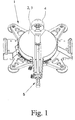
- the miter saw shown in the figures is based on the essential, for the Explanation of the invention necessary components limited. So is the in Fig. 1 illustrated miter saw substantially only from a support 1 and a workpiece support surface 2 forming turntable 3. All others for a miter saw, although functionally necessary, but to explain the invention unnecessary components, such as z. As an attached to an indicated here tilt arrangement 4 bracket with a swiveling saw unit, are intentionally in the figures has been omitted to focus attention on the essential.
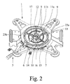
- Fig. 2 shows the miter saw according to the invention without turntable 3, wherein a normally attached to the turntable 3 actuator 5 here continues is shown to illustrate the operation.
- a turntable fixing device 6 is operated, about the turntable 3 with respect to the carrier 1 graded and fixed reproducible can be, for example, by the turntable fixing device 6 in Intervention with the provided in a miter 7 miter scoring device.
- the miter notches are so in the along the circumference of the turntable 3 extending Miter 7 arranged that with the turntable fixing device 6 a few predetermined first angular positions are stepped can.
- Fig. 2 further shows a preferred turntable fixing device 8, with which it is additionally possible, the turntable 3 opposite to fix the carrier 1 in a further second angular position, wherein the particular advantage of the invention is achieved in that the second angular position at the same time stepless and reproducible.
- Stepless means that in Contrary to the first turntable fixing device 6 shown above not only a few angular positions are selectable, but that any other angular positions, completely independent of predetermined stop marks, can be adjusted.
- FIG. 2 The illustrated in Fig. 2 preferred embodiment of an inventive Miter saw shows the turntable fixing device 8, the present from a formed to a latching arm base 9, a locking arm fixing device 10 and a locking means 11 a, b, wherein the latching arm 9 and the Locking arm fixing device 10 rotatably mounted on a cylindrical holder 12 of the Carrier 1 are stored.
- the cylindrical holder 12 encloses at the same time concentric with the axis of rotation of the turntable.
- the latching arm 9 is in any desired angular position with the aid of the latching arm fixing device 10 fixable with respect to the carrier 1, and via the locking means 11a, b, the turntable 3 can be detachably connected to the latching arm 9.
- the turntable 3 is mounted on the carrier 1 is, in particular so that the turntable 3 via a sliding guide 13 on the Carrier 1 rests. Furthermore, it is assumed that in the starting position of the Locking arm 9 is connected to the turntable 3 via the locking means 11 a, b. By loosening the locking arm fixing device 10 of the locking arm 9 is about the cylindrical Holder 12 freely rotatable, and thus follows one steplessly through the User made rotation of the turntable 3 in the desired second Angular position.
- the locking arm 9 in the second continuously adjusted angular position can be securely fixed.
- the turntable 3 in any other position for. B. the first angular position to be offset, the - the second angular position defining - locking arm 9 while it is stationary. If the second angular position the turntable 3 is to be found again, is the turntable 3 only to turn again in the direction of the second angular position, so long until the turntable 3 again with the locking arm 9 via the locking means 11 a, b is fixed.
- the latching arm fixing device 10 is in the illustrated preferred embodiment designed so that the cylindrical holder 12 and the locking arm fixing device 10 via corresponding threads engaged with each other stand and the locking arm 9 by screw action between the locking arm fixing device 10 and the carrier 1 clamped and thus fixed can.
- the region of the cylindrical holder 12, that of the locking arm 9 is enclosed and / or the locking arm 9 no thread on, so that the mobility the locking arm 9 in the case of the released locking arm fixing device 10th is ensured.
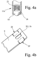
- Figs. 2 and 4 is a preferred embodiment of the latching arm fixing device 10, wherein the locking arm fixing device 10 is divided into two parts is constructed, namely a locking arm actuator 14 and a locking arm screw 15 includes.
- the two mentioned elements are the same constructed so that they are connected to each other in any rotational position can be.
- the locking means 11a, b is divided into two and to a part 11a associated with the turntable 3 and the other part 11b the latching arm 9.
- Fig. 2 shows Fig. 2 also the part 11 a of the locking means 11 a, b, which associated with the turntable 3 is, although the turntable 3 is not shown.
- the part 11a of the locking means 11a, b firmly associated with the turntable 3, which in Fig. 3 is clearly visible.
- the rotary table 3 associated part 11 a of the locking means 11 a, b exists here from a ball holder 18 with a ball 19.
- the ball holder 18 can also be seen in FIGS. 2 and 3.
- the open and in the assembled state of the Turntable 3 to the other part 11b of the locking means 11a, b facing end the ball holder 18 is designed so that the ball 19 fixed in the ball holder 18 is held and partially out of the open end of the ball holder 18 can stand out.
- the other part 11b of the locking means 11a, b is accordingly as a ball seat 20 formed in the latching arm 9.
- the ball seat 20 is made preferably from a recess provided in the locking arm 9 recess or depression.
- the rotary table 3 associated part 11a of the locking means 11a, b is such arranged that he in the assembled state of the miter saw according to the invention in the, associated with the latching arm 9, corresponding other part 11 b of the Arret istsstoffs 11 a, b, so in the ball seat 20, can engage. This happens by overcoming a certain resistance while turning Pushing over both parts of the locking means 11 a, b, so at Turning the ball holder 18 with the ball 19 in the ball seat 20th
- FIG. 4 a shows a detailed view of the ball holder 18.
- the ball 19 by a spring 21 against the Opening the ball holder 18 is pressed.
- the through the spring bearing of the ball 19 achieved in the ball holder 18 elasticity of the locking means 11 a, b can be further improved by that preferably also the locking arm.
- 9 is formed elastically, in particular so that an elastic deformation of Rastarmes 9 substantially in the axial direction of the cylindrical holder 12th is provided, ie in the direction of the vertical axis around which the turntable. 3 rotates.
- Miter saw is placed on an elastic bearing of the ball 19 in omitted the ball holder 18 and only the locking arm 9 in the above-described Way elastically formed.
- the locking means 11a, b is preferably designed so that a "gentle" Engagement of both parts of the locking means 11a, b is possible.
- a "gentle" Engagement of both parts of the locking means 11a, b is possible.
- This is achieved in that the resulting upon rotation of the turntable 3 first Berzierstellen 22 between the ball 19 and the locking arm 9 ramp-shaped flattened, so that a resistance to the rotational movement continuously can build up to the ball 19 in the ball seat 20 jump locks.
- Stops 23 a, b provided, the movement of the latching arm 9 and thus the Limit maximum positions of possible second angular positions.
- the illustrated Stops 23a, b preferably mark different amounts Angular positions.
- the two different, designated by the stops 23a, b Angular positions are preferably 50 ° and 60 °.
Landscapes
- Engineering & Computer Science (AREA)
- Mechanical Engineering (AREA)
- Life Sciences & Earth Sciences (AREA)
- Wood Science & Technology (AREA)
- Forests & Forestry (AREA)
- Sawing (AREA)
- Magnetic Resonance Imaging Apparatus (AREA)
Abstract
Description
- Winkelstellung zurückkehren soll, kann der Drehtisch durch Lösen der über das Arretierungsmittel bewirkten Verbindung von Drehtisch und Basis von der Basis getrennt werden, ohne daß die Basis die zuvor stufenlos und reproduzierbar definierte Winkelstellung verliert. Der nunmehr frei bewegliche Drehtisch läßt sich sodann ohne weiteres in eine andere bzw. die erste Winkelstellung bringen.
- Fig. 1
- ein bevorzugtes Ausführungsbeispiel einer erfindungsgemäßen Gehrungssäge im montierten Zustand,
- Fig. 2
- die Gehrungssäge aus Fig. 1 mit demontiertem Drehtisch,
- Fig. 3
- die unterseitige Ansicht des Drehtisches aus Fig. 1 und
- Fig. 4a, b
- eine Detailansicht der Gehrungssäge aus Fig. 2 zur Verdeutlichung des Arretierungsmittels.
Claims (13)
- Gehrungssäge mit Winkeleinstellung mit
einem Träger (1),
einem am oder im Träger (1) drehbar angeordneten, eine Werkstückauflagefläche (2) bildenden Drehtisch (3) und
einer Drehtisch-Fixiervorrichtung (8) zur Fixierung des Drehtisches (3) gegenüber dem Träger (1) in bestimmten, reproduzierbaren Winkelstellungen,
dadurch gekennzeichnet, daß die Drehtisch-Fixiervorrichtung (8) die Einstellung mindestens einer Winkelstellung zugleich stufenlos und reproduzierbar ermöglicht. - Gehrungssäge nach Anspruch 1, dadurch gekennzeichnet, daß die Drehtisch-Fixiervorrichtung (8) eine am Träger (1) drehbar gelagerte und in einer stufenlos einstellbaren Winkelstellung fixierbare Basis (9) aufweist, daß der Drehtisch (3) auch gegenüber der Basis (9) drehbar ist und daß der Drehtisch (3) in einer bestimmten Drehstellung gegenüber der Basis (9) mit dieser über ein Arretierungsmittel (11a, b) lösbar verbunden ist.
- Gehrungssäge nach Anspruch 2, dadurch gekennzeichnet, daß die Basis (9), sofern sie einerseits nicht am Träger (1) fixiert, andererseits über das Arretierungsmittel (11a, b) mit dem Drehtisch (3) verbunden ist, vom Drehtisch (3) drehend mitführbar ist.
- Gehrungssäge nach Anspruch 2 oder 3, dadurch gekennzeichnet, daß die Drehtisch-Fixiervorrichtung (8) einen Rastarm als Basis (9) und eine Rastarm-Fixiervorrichtung (10) aufweist, daß der Rastarm (9) drehbar, vorzugsweise auf einer zylindrischen Halterung (12) des Trägers (1), gelagert ist und daß der Rastarm (9) durch die Rastarm-Fixiervorrichtung (10) in beliebiger Winkelstellung am Träger (1) fixierbar ist.
- Gehrungssäge nach Anspruch 4, dadurch gekennzeichnet, daß die zylindrische Halterung (12) und die Rastarm-Fixiervorrichtung (10) über korrespondierende Gewindegänge miteinander in Eingriff stehen und daß der Rastarm (9) somit durch eine Schraubspannwirkung zwischen der Rastarm-Fixiervorrichtung (10) und dem Träger (1) festklemmbar ist.
- Gehrungssäge nach Anspruch 4 oder 5, dadurch gekennzeichnet, daß die Rastarm-Fixiervorrichtung (10) ein Rastarm-Betätigungselement (14) und ein mit der zylindrischen Halterung (12) in Schraubeingriff stehendes Rastarm-Schraubelement (15) aufweist.
- Gehrungssäge nach Anspruch 6, dadurch gekennzeichnet, daß das Rastarm-Betätigungselement (14) mit dem Rastarm-Schraubelement (15) mittels einer Langloch-Zapfenverbindung (16, 17) verbunden ist.
- Gehrungssäge nach einem der Ansprüche 2 bis 7, dadurch gekennzeichnet, daß das Arretierungsmittel (11a, b) zu einem Teil (11a) dem Drehtisch (3) und zum anderen Teil (11b) der Basis (9) zugeordnet ist, und daß bei fixierter Basis (9) durch Drehen des Drehtisches (3) der eine Teil (11a) des Arretierungsmittels (11a, b) in Eingriff mit dem anderen Teil (11b) des Arretierungsmittels (11a, b) bringbar ist.
- Gehrungssäge nach Anspruch 8, dadurch gekennzeichnet, daß der eine Teil (11a) des Arretierungsmittels (11a, b) eine Kugelhalterung (18) mit einer Kugel (19) aufweist, daß der andere Teil (11b) des Arretierungsmittels (11a, b) als eine Kugelaufnahme (20) in der Basis (9) ausgebildet ist, mit der die Kugel (19) in Eingriff bringbar ist.
- Gehrungssäge nach Anspruch 9, dadurch gekennzeichnet, daß der eine Teil (11a) und/oder der andere Teil (11b) des Arretierungsmittels (11a, b) elastisch ausgebildet ist, insbesondere indem die Kugel (19) durch eine Feder (21) in der Kugelhalterung (18) vorgespannt ist und/oder die Basis (9) einer ― insbesondere in bzw. parallel zur Richtung der Drehachse des Drehtisches (3) wirkenden ― Kraft federnd nachgibt.
- Gehrungssäge nach Anspruch 9 oder 10, dadurch gekennzeichnet, daß der der Basis (9) zugeordnete Teil (11b) des Arretierungsmittels (11a, b) an den sich bei Drehung des Drehtisches (3) mit der Kugel (19) ergebenden Berührstellen (22) rampenförmig abgeflacht ist.
- Gehrungssäge nach einem der Ansprüche 2 bis 11, dadurch gekennzeichnet, daß der Träger (1) mindestens einen Anschlag (23a, b) umfaßt, der die Drehbewegung der Basis (9) in einer maximalen Winkeleinstellung begrenzt.
- Gehrungssäge nach Anspruch 12, dadurch gekennzeichnet, daß im Falle mehrerer Anschläge (23a, b) durch die Anschläge (23a, b) unterschiedliche Winkelstellungen definiert werden, insbesondere 50° und 60° gegenüber einer Mittelstellung.
Priority Applications (6)
| Application Number | Priority Date | Filing Date | Title |
|---|---|---|---|
| ES04010504T ES2270215T3 (es) | 2004-05-03 | 2004-05-03 | Sierra para cortar ingletes con ajuste angular. |
| DE200450001342 DE502004001342D1 (de) | 2004-05-03 | 2004-05-03 | Gehrungssäge mit Winkeleinstellung |
| EP20040010504 EP1595630B1 (de) | 2004-05-03 | 2004-05-03 | Gehrungssäge mit Winkeleinstellung |
| AT04010504T ATE337880T1 (de) | 2004-05-03 | 2004-05-03 | Gehrungssäge mit winkeleinstellung |
| US11/110,723 US7302879B2 (en) | 2004-05-03 | 2005-04-21 | Miter saw with angle adjustment |
| CA 2505960 CA2505960C (en) | 2004-05-03 | 2005-05-02 | Miter saw with angle adjustment |
Applications Claiming Priority (1)
| Application Number | Priority Date | Filing Date | Title |
|---|---|---|---|
| EP20040010504 EP1595630B1 (de) | 2004-05-03 | 2004-05-03 | Gehrungssäge mit Winkeleinstellung |
Publications (2)
| Publication Number | Publication Date |
|---|---|
| EP1595630A1 true EP1595630A1 (de) | 2005-11-16 |
| EP1595630B1 EP1595630B1 (de) | 2006-08-30 |
Family
ID=34924840
Family Applications (1)
| Application Number | Title | Priority Date | Filing Date |
|---|---|---|---|
| EP20040010504 Expired - Lifetime EP1595630B1 (de) | 2004-05-03 | 2004-05-03 | Gehrungssäge mit Winkeleinstellung |
Country Status (6)
| Country | Link |
|---|---|
| US (1) | US7302879B2 (de) |
| EP (1) | EP1595630B1 (de) |
| AT (1) | ATE337880T1 (de) |
| CA (1) | CA2505960C (de) |
| DE (1) | DE502004001342D1 (de) |
| ES (1) | ES2270215T3 (de) |
Cited By (1)
| Publication number | Priority date | Publication date | Assignee | Title |
|---|---|---|---|---|
| EP1886752A1 (de) * | 2006-08-11 | 2008-02-13 | Metabowerke GmbH | Kapp- und Gehrungssäge mit einem Drehtisch |
Families Citing this family (6)
| Publication number | Priority date | Publication date | Assignee | Title |
|---|---|---|---|---|
| WO2005102626A2 (en) * | 2004-04-15 | 2005-11-03 | Milwaukee Electric Tool Corporation | Saw, such as a miter saw |
| US8061251B2 (en) * | 2004-04-15 | 2011-11-22 | Milwaukee Electric Tool Corporation | Miter adjustment assembly for a saw |
| USD556224S1 (en) * | 2004-04-15 | 2007-11-27 | Milwaukee Electric Tool Corporation | Portion of a miter saw |
| USD602964S1 (en) | 2005-04-15 | 2009-10-27 | Milwaukee Electric Tool Corporation | Miter saw motor housing |
| US8002253B2 (en) | 2008-06-20 | 2011-08-23 | Robert Bosch Gmbh | Button actuated detent system |
| US9833849B2 (en) | 2016-01-18 | 2017-12-05 | Tti (Macao Commercial Offshore) Limited | Miter saw |
Citations (6)
| Publication number | Priority date | Publication date | Assignee | Title |
|---|---|---|---|---|
| US3487863A (en) * | 1967-03-09 | 1970-01-06 | Thomas Robinson & Son Ltd | Indexing of rotary members of machines |
| US5207141A (en) * | 1991-01-30 | 1993-05-04 | Ryobi Limited | Turntable positioning device of desk type cutting machine |
| EP0779122A2 (de) * | 1995-12-12 | 1997-06-18 | Black & Decker Inc. | Werkstückdrehtisch |
| JPH11226905A (ja) * | 1998-02-19 | 1999-08-24 | Hitachi Koki Co Ltd | 卓上切断機の角度インデックス装置 |
| US20030200852A1 (en) * | 2002-04-30 | 2003-10-30 | Ezequiel Romo | Miter cut fine adjustment mechanism |
| US20040079214A1 (en) * | 2001-02-08 | 2004-04-29 | Meredith Daryl S. | Miter saw |
Family Cites Families (8)
| Publication number | Priority date | Publication date | Assignee | Title |
|---|---|---|---|---|
| US5249496A (en) * | 1992-08-13 | 1993-10-05 | Milwaukee Electric Tool Corporation | Indexing detent override mechanism |
| GB2304075B (en) * | 1995-08-10 | 1999-10-20 | Milwaukee Electric Tool Corp | Indexing override mechanism for a slide compound miter saw |
| US5937720A (en) * | 1995-08-10 | 1999-08-17 | Milwaukee Electric Tool Corporation | Lower blade guard actuating mechanism for a slide compound miter saw |
| US5819624A (en) * | 1996-07-30 | 1998-10-13 | Milwaukee Electric Tool Corporation | Indexing override mechanism for a slide compound miter saw |
| CN1259892A (zh) | 1997-06-09 | 2000-07-12 | 伊利克特拉贝库姆股份公司 | 移动式台式圆盘锯 |
| US6513412B2 (en) | 2001-01-09 | 2003-02-04 | Porter Cable Corp. | Adjustment mechanism |
| US6810780B2 (en) * | 2001-05-10 | 2004-11-02 | Black & Decker Inc. | Miter detent override for a sliding compound miter saw |
| TW569908U (en) | 2002-09-26 | 2004-01-01 | P & F Brother Ind Corp | Apparatus for adjusting and aligning slant cutting angle of cutting machine |
-
2004
- 2004-05-03 DE DE200450001342 patent/DE502004001342D1/de not_active Expired - Lifetime
- 2004-05-03 AT AT04010504T patent/ATE337880T1/de active
- 2004-05-03 ES ES04010504T patent/ES2270215T3/es not_active Expired - Lifetime
- 2004-05-03 EP EP20040010504 patent/EP1595630B1/de not_active Expired - Lifetime
-
2005
- 2005-04-21 US US11/110,723 patent/US7302879B2/en not_active Expired - Fee Related
- 2005-05-02 CA CA 2505960 patent/CA2505960C/en not_active Expired - Fee Related
Patent Citations (6)
| Publication number | Priority date | Publication date | Assignee | Title |
|---|---|---|---|---|
| US3487863A (en) * | 1967-03-09 | 1970-01-06 | Thomas Robinson & Son Ltd | Indexing of rotary members of machines |
| US5207141A (en) * | 1991-01-30 | 1993-05-04 | Ryobi Limited | Turntable positioning device of desk type cutting machine |
| EP0779122A2 (de) * | 1995-12-12 | 1997-06-18 | Black & Decker Inc. | Werkstückdrehtisch |
| JPH11226905A (ja) * | 1998-02-19 | 1999-08-24 | Hitachi Koki Co Ltd | 卓上切断機の角度インデックス装置 |
| US20040079214A1 (en) * | 2001-02-08 | 2004-04-29 | Meredith Daryl S. | Miter saw |
| US20030200852A1 (en) * | 2002-04-30 | 2003-10-30 | Ezequiel Romo | Miter cut fine adjustment mechanism |
Non-Patent Citations (1)
| Title |
|---|
| PATENT ABSTRACTS OF JAPAN vol. 1999, no. 13 30 November 1999 (1999-11-30) * |
Cited By (1)
| Publication number | Priority date | Publication date | Assignee | Title |
|---|---|---|---|---|
| EP1886752A1 (de) * | 2006-08-11 | 2008-02-13 | Metabowerke GmbH | Kapp- und Gehrungssäge mit einem Drehtisch |
Also Published As
| Publication number | Publication date |
|---|---|
| US7302879B2 (en) | 2007-12-04 |
| EP1595630B1 (de) | 2006-08-30 |
| DE502004001342D1 (de) | 2006-10-12 |
| ES2270215T3 (es) | 2007-04-01 |
| ATE337880T1 (de) | 2006-09-15 |
| CA2505960A1 (en) | 2005-11-03 |
| US20050241452A1 (en) | 2005-11-03 |
| CA2505960C (en) | 2008-08-19 |
Similar Documents
| Publication | Publication Date | Title |
|---|---|---|
| DE4322672B4 (de) | Motorisch angetriebene Feinsäge | |
| DE3943594C2 (de) | ||
| DE4008224C2 (de) | ||
| DE10062645C5 (de) | Kreissägen mit einem Gehrungswinkeleinstellmechanismus | |
| DE60202900T2 (de) | Kapp- und Gehrungssäge umfassend einen Tisch mit einem Einrastsystem und einem Feststellsystem | |
| EP0144490A2 (de) | Bohr- und Fräsführer für auswechselbare Antriebsmaschinen | |
| DE19523348A1 (de) | Einstellmechanismus des Schrägstellungswinkels einer Verbund-Gehrungssäge | |
| WO1990002633A2 (de) | Spanneinrichtung | |
| WO2019179789A1 (de) | Fräsadapter für einen werktisch | |
| EP0223981A1 (de) | Werkstückhaltevorrichtung | |
| DE4236425C2 (de) | Gehrungssäge | |
| EP2183072A1 (de) | Handwerkzeugmaschine | |
| EP1595630A1 (de) | Gehrungssäge mit Winkeleinstellung | |
| DE19937827A1 (de) | Werkzeug mit einstellbarem Anschlag | |
| DE112009005456B4 (de) | Elektrisches werkzeug mit tiefeneinstelleinrichtung | |
| EP2363233B1 (de) | Werkzeuggerät | |
| DE3813852C2 (de) | ||
| EP0118077B1 (de) | Gehrungsanschlag | |
| EP2974839B1 (de) | Hand-trennmaschine mit zwei gehrungslagern | |
| DE102009025108B4 (de) | Dekupiersäge mit verstellbarem Arbeitstisch | |
| DE10229671A1 (de) | Haltevorrichtung für Motorsäge, insbesondere für Kettensäge | |
| DE19519645C1 (de) | Querschneideinrichtung | |
| EP3702100A1 (de) | Anschlagvorrichtung | |
| DE102009025110A1 (de) | Kippvorrichtung mit einstellbarem Kippwinkel | |
| DE19950494A1 (de) | Schiebetisch für eine Tischkreissäge |
Legal Events
| Date | Code | Title | Description |
|---|---|---|---|
| PUAI | Public reference made under article 153(3) epc to a published international application that has entered the european phase |
Free format text: ORIGINAL CODE: 0009012 |
|
| 17P | Request for examination filed |
Effective date: 20050517 |
|
| AK | Designated contracting states |
Kind code of ref document: A1 Designated state(s): AT BE BG CH CY CZ DE DK EE ES FI FR GB GR HU IE IT LI LU MC NL PL PT RO SE SI SK TR |
|
| AX | Request for extension of the european patent |
Extension state: AL HR LT LV MK |
|
| GRAP | Despatch of communication of intention to grant a patent |
Free format text: ORIGINAL CODE: EPIDOSNIGR1 |
|
| GRAS | Grant fee paid |
Free format text: ORIGINAL CODE: EPIDOSNIGR3 |
|
| AKX | Designation fees paid |
Designated state(s): AT BE BG CH CY CZ DE DK EE ES FI FR GB GR HU IE IT LI LU MC NL PL PT RO SE SI SK TR |
|
| GRAA | (expected) grant |
Free format text: ORIGINAL CODE: 0009210 |
|
| AK | Designated contracting states |
Kind code of ref document: B1 Designated state(s): AT BE BG CH CY CZ DE DK EE ES FI FR GB GR HU IE IT LI LU MC NL PL PT RO SE SI SK TR |
|
| PG25 | Lapsed in a contracting state [announced via postgrant information from national office to epo] |
Ref country code: CZ Free format text: LAPSE BECAUSE OF FAILURE TO SUBMIT A TRANSLATION OF THE DESCRIPTION OR TO PAY THE FEE WITHIN THE PRESCRIBED TIME-LIMIT Effective date: 20060830 Ref country code: SK Free format text: LAPSE BECAUSE OF FAILURE TO SUBMIT A TRANSLATION OF THE DESCRIPTION OR TO PAY THE FEE WITHIN THE PRESCRIBED TIME-LIMIT Effective date: 20060830 Ref country code: SI Free format text: LAPSE BECAUSE OF FAILURE TO SUBMIT A TRANSLATION OF THE DESCRIPTION OR TO PAY THE FEE WITHIN THE PRESCRIBED TIME-LIMIT Effective date: 20060830 Ref country code: IT Free format text: LAPSE BECAUSE OF FAILURE TO SUBMIT A TRANSLATION OF THE DESCRIPTION OR TO PAY THE FEE WITHIN THE PRESCRIBED TIME-LIMIT;WARNING: LAPSES OF ITALIAN PATENTS WITH EFFECTIVE DATE BEFORE 2007 MAY HAVE OCCURRED AT ANY TIME BEFORE 2007. THE CORRECT EFFECTIVE DATE MAY BE DIFFERENT FROM THE ONE RECORDED. Effective date: 20060830 Ref country code: NL Free format text: LAPSE BECAUSE OF FAILURE TO SUBMIT A TRANSLATION OF THE DESCRIPTION OR TO PAY THE FEE WITHIN THE PRESCRIBED TIME-LIMIT Effective date: 20060830 Ref country code: FI Free format text: LAPSE BECAUSE OF FAILURE TO SUBMIT A TRANSLATION OF THE DESCRIPTION OR TO PAY THE FEE WITHIN THE PRESCRIBED TIME-LIMIT Effective date: 20060830 Ref country code: IE Free format text: LAPSE BECAUSE OF FAILURE TO SUBMIT A TRANSLATION OF THE DESCRIPTION OR TO PAY THE FEE WITHIN THE PRESCRIBED TIME-LIMIT Effective date: 20060830 Ref country code: PL Free format text: LAPSE BECAUSE OF FAILURE TO SUBMIT A TRANSLATION OF THE DESCRIPTION OR TO PAY THE FEE WITHIN THE PRESCRIBED TIME-LIMIT Effective date: 20060830 Ref country code: RO Free format text: LAPSE BECAUSE OF FAILURE TO SUBMIT A TRANSLATION OF THE DESCRIPTION OR TO PAY THE FEE WITHIN THE PRESCRIBED TIME-LIMIT Effective date: 20060830 |
|
| REG | Reference to a national code |
Ref country code: GB Ref legal event code: FG4D Free format text: NOT ENGLISH |
|
| REG | Reference to a national code |
Ref country code: CH Ref legal event code: EP Ref country code: CH Ref legal event code: NV Representative=s name: KELLER & PARTNER PATENTANWAELTE AG |
|
| REG | Reference to a national code |
Ref country code: IE Ref legal event code: FG4D Free format text: LANGUAGE OF EP DOCUMENT: GERMAN |
|
| REF | Corresponds to: |
Ref document number: 502004001342 Country of ref document: DE Date of ref document: 20061012 Kind code of ref document: P |
|
| GBT | Gb: translation of ep patent filed (gb section 77(6)(a)/1977) |
Effective date: 20061102 |
|
| PG25 | Lapsed in a contracting state [announced via postgrant information from national office to epo] |
Ref country code: SE Free format text: LAPSE BECAUSE OF FAILURE TO SUBMIT A TRANSLATION OF THE DESCRIPTION OR TO PAY THE FEE WITHIN THE PRESCRIBED TIME-LIMIT Effective date: 20061130 Ref country code: DK Free format text: LAPSE BECAUSE OF FAILURE TO SUBMIT A TRANSLATION OF THE DESCRIPTION OR TO PAY THE FEE WITHIN THE PRESCRIBED TIME-LIMIT Effective date: 20061130 Ref country code: BG Free format text: LAPSE BECAUSE OF FAILURE TO SUBMIT A TRANSLATION OF THE DESCRIPTION OR TO PAY THE FEE WITHIN THE PRESCRIBED TIME-LIMIT Effective date: 20061130 |
|
| PG25 | Lapsed in a contracting state [announced via postgrant information from national office to epo] |
Ref country code: PT Free format text: LAPSE BECAUSE OF FAILURE TO SUBMIT A TRANSLATION OF THE DESCRIPTION OR TO PAY THE FEE WITHIN THE PRESCRIBED TIME-LIMIT Effective date: 20070206 |
|
| NLV1 | Nl: lapsed or annulled due to failure to fulfill the requirements of art. 29p and 29m of the patents act | ||
| REG | Reference to a national code |
Ref country code: ES Ref legal event code: FG2A Ref document number: 2270215 Country of ref document: ES Kind code of ref document: T3 |
|
| ET | Fr: translation filed | ||
| REG | Reference to a national code |
Ref country code: IE Ref legal event code: FD4D |
|
| PLBE | No opposition filed within time limit |
Free format text: ORIGINAL CODE: 0009261 |
|
| STAA | Information on the status of an ep patent application or granted ep patent |
Free format text: STATUS: NO OPPOSITION FILED WITHIN TIME LIMIT |
|
| 26N | No opposition filed |
Effective date: 20070531 |
|
| BERE | Be: lapsed |
Owner name: METABOWERKE G.M.B.H. Effective date: 20070531 |
|
| PG25 | Lapsed in a contracting state [announced via postgrant information from national office to epo] |
Ref country code: MC Free format text: LAPSE BECAUSE OF NON-PAYMENT OF DUE FEES Effective date: 20070531 |
|
| PG25 | Lapsed in a contracting state [announced via postgrant information from national office to epo] |
Ref country code: BE Free format text: LAPSE BECAUSE OF NON-PAYMENT OF DUE FEES Effective date: 20070531 |
|
| PG25 | Lapsed in a contracting state [announced via postgrant information from national office to epo] |
Ref country code: GR Free format text: LAPSE BECAUSE OF FAILURE TO SUBMIT A TRANSLATION OF THE DESCRIPTION OR TO PAY THE FEE WITHIN THE PRESCRIBED TIME-LIMIT Effective date: 20061201 |
|
| PG25 | Lapsed in a contracting state [announced via postgrant information from national office to epo] |
Ref country code: EE Free format text: LAPSE BECAUSE OF FAILURE TO SUBMIT A TRANSLATION OF THE DESCRIPTION OR TO PAY THE FEE WITHIN THE PRESCRIBED TIME-LIMIT Effective date: 20060830 |
|
| PGRI | Patent reinstated in contracting state [announced from national office to epo] |
Ref country code: IT Effective date: 20080601 |
|
| PG25 | Lapsed in a contracting state [announced via postgrant information from national office to epo] |
Ref country code: CY Free format text: LAPSE BECAUSE OF FAILURE TO SUBMIT A TRANSLATION OF THE DESCRIPTION OR TO PAY THE FEE WITHIN THE PRESCRIBED TIME-LIMIT Effective date: 20060830 Ref country code: LU Free format text: LAPSE BECAUSE OF NON-PAYMENT OF DUE FEES Effective date: 20070503 |
|
| PG25 | Lapsed in a contracting state [announced via postgrant information from national office to epo] |
Ref country code: TR Free format text: LAPSE BECAUSE OF FAILURE TO SUBMIT A TRANSLATION OF THE DESCRIPTION OR TO PAY THE FEE WITHIN THE PRESCRIBED TIME-LIMIT Effective date: 20060830 Ref country code: HU Free format text: LAPSE BECAUSE OF FAILURE TO SUBMIT A TRANSLATION OF THE DESCRIPTION OR TO PAY THE FEE WITHIN THE PRESCRIBED TIME-LIMIT Effective date: 20070301 |
|
| PGFP | Annual fee paid to national office [announced via postgrant information from national office to epo] |
Ref country code: ES Payment date: 20110524 Year of fee payment: 8 Ref country code: CH Payment date: 20110525 Year of fee payment: 8 |
|
| PGFP | Annual fee paid to national office [announced via postgrant information from national office to epo] |
Ref country code: AT Payment date: 20110520 Year of fee payment: 8 |
|
| PGFP | Annual fee paid to national office [announced via postgrant information from national office to epo] |
Ref country code: IT Payment date: 20110527 Year of fee payment: 8 |
|
| REG | Reference to a national code |
Ref country code: CH Ref legal event code: PL |
|
| REG | Reference to a national code |
Ref country code: AT Ref legal event code: MM01 Ref document number: 337880 Country of ref document: AT Kind code of ref document: T Effective date: 20120503 |
|
| PG25 | Lapsed in a contracting state [announced via postgrant information from national office to epo] |
Ref country code: AT Free format text: LAPSE BECAUSE OF NON-PAYMENT OF DUE FEES Effective date: 20120503 Ref country code: LI Free format text: LAPSE BECAUSE OF NON-PAYMENT OF DUE FEES Effective date: 20120531 Ref country code: CH Free format text: LAPSE BECAUSE OF NON-PAYMENT OF DUE FEES Effective date: 20120531 |
|
| PG25 | Lapsed in a contracting state [announced via postgrant information from national office to epo] |
Ref country code: IT Free format text: LAPSE BECAUSE OF FAILURE TO SUBMIT A TRANSLATION OF THE DESCRIPTION OR TO PAY THE FEE WITHIN THE PRESCRIBED TIME-LIMIT Effective date: 20120503 |
|
| REG | Reference to a national code |
Ref country code: ES Ref legal event code: FD2A Effective date: 20130820 |
|
| PG25 | Lapsed in a contracting state [announced via postgrant information from national office to epo] |
Ref country code: ES Free format text: LAPSE BECAUSE OF NON-PAYMENT OF DUE FEES Effective date: 20120504 |
|
| REG | Reference to a national code |
Ref country code: FR Ref legal event code: PLFP Year of fee payment: 13 |
|
| REG | Reference to a national code |
Ref country code: FR Ref legal event code: PLFP Year of fee payment: 14 |
|
| REG | Reference to a national code |
Ref country code: FR Ref legal event code: PLFP Year of fee payment: 15 |
|
| PGFP | Annual fee paid to national office [announced via postgrant information from national office to epo] |
Ref country code: FR Payment date: 20200519 Year of fee payment: 17 Ref country code: DE Payment date: 20200525 Year of fee payment: 17 |
|
| PGFP | Annual fee paid to national office [announced via postgrant information from national office to epo] |
Ref country code: GB Payment date: 20200522 Year of fee payment: 17 |
|
| REG | Reference to a national code |
Ref country code: DE Ref legal event code: R119 Ref document number: 502004001342 Country of ref document: DE |
|
| GBPC | Gb: european patent ceased through non-payment of renewal fee |
Effective date: 20210503 |
|
| PG25 | Lapsed in a contracting state [announced via postgrant information from national office to epo] |
Ref country code: GB Free format text: LAPSE BECAUSE OF NON-PAYMENT OF DUE FEES Effective date: 20210503 Ref country code: DE Free format text: LAPSE BECAUSE OF NON-PAYMENT OF DUE FEES Effective date: 20211201 |
|
| PG25 | Lapsed in a contracting state [announced via postgrant information from national office to epo] |
Ref country code: FR Free format text: LAPSE BECAUSE OF NON-PAYMENT OF DUE FEES Effective date: 20210531 |