EP1595648A2 - Bride de serrage en deux parties - Google Patents
Bride de serrage en deux parties Download PDFInfo
- Publication number
- EP1595648A2 EP1595648A2 EP05010050A EP05010050A EP1595648A2 EP 1595648 A2 EP1595648 A2 EP 1595648A2 EP 05010050 A EP05010050 A EP 05010050A EP 05010050 A EP05010050 A EP 05010050A EP 1595648 A2 EP1595648 A2 EP 1595648A2
- Authority
- EP
- European Patent Office
- Prior art keywords
- clamping
- base
- leg
- finger
- der
- Prior art date
- Legal status (The legal status is an assumption and is not a legal conclusion. Google has not performed a legal analysis and makes no representation as to the accuracy of the status listed.)
- Withdrawn
Links
Images
Classifications
-
- B—PERFORMING OPERATIONS; TRANSPORTING
- B23—MACHINE TOOLS; METAL-WORKING NOT OTHERWISE PROVIDED FOR
- B23B—TURNING; BORING
- B23B27/00—Tools for turning or boring machines; Tools of a similar kind in general; Accessories therefor
- B23B27/14—Cutting tools of which the bits or tips or cutting inserts are of special material
- B23B27/16—Cutting tools of which the bits or tips or cutting inserts are of special material with exchangeable cutting bits or cutting inserts, e.g. able to be clamped
- B23B27/1666—Cutting tools of which the bits or tips or cutting inserts are of special material with exchangeable cutting bits or cutting inserts, e.g. able to be clamped with plate-like cutting inserts clamped by a clamping member acting almost perpendicularly on chip-forming plane
-
- B—PERFORMING OPERATIONS; TRANSPORTING
- B25—HAND TOOLS; PORTABLE POWER-DRIVEN TOOLS; MANIPULATORS
- B25B—TOOLS OR BENCH DEVICES NOT OTHERWISE PROVIDED FOR, FOR FASTENING, CONNECTING, DISENGAGING, OR HOLDING
- B25B5/00—Clamps
- B25B5/06—Arrangements for positively actuating jaws
- B25B5/08—Arrangements for positively actuating jaws using cams
-
- B—PERFORMING OPERATIONS; TRANSPORTING
- B25—HAND TOOLS; PORTABLE POWER-DRIVEN TOOLS; MANIPULATORS
- B25B—TOOLS OR BENCH DEVICES NOT OTHERWISE PROVIDED FOR, FOR FASTENING, CONNECTING, DISENGAGING, OR HOLDING
- B25B5/00—Clamps
- B25B5/06—Arrangements for positively actuating jaws
- B25B5/10—Arrangements for positively actuating jaws using screws
-
- B—PERFORMING OPERATIONS; TRANSPORTING
- B23—MACHINE TOOLS; METAL-WORKING NOT OTHERWISE PROVIDED FOR
- B23B—TURNING; BORING
- B23B2260/00—Details of constructional elements
- B23B2260/03—Clamps
-
- Y—GENERAL TAGGING OF NEW TECHNOLOGICAL DEVELOPMENTS; GENERAL TAGGING OF CROSS-SECTIONAL TECHNOLOGIES SPANNING OVER SEVERAL SECTIONS OF THE IPC; TECHNICAL SUBJECTS COVERED BY FORMER USPC CROSS-REFERENCE ART COLLECTIONS [XRACs] AND DIGESTS
- Y10—TECHNICAL SUBJECTS COVERED BY FORMER USPC
- Y10T—TECHNICAL SUBJECTS COVERED BY FORMER US CLASSIFICATION
- Y10T407/00—Cutters, for shaping
- Y10T407/22—Cutters, for shaping including holder having seat for inserted tool
- Y10T407/2272—Cutters, for shaping including holder having seat for inserted tool with separate means to fasten tool to holder
- Y10T407/2274—Apertured tool
- Y10T407/2276—Apertured tool with means projecting through aperture to force tool laterally against reaction surface
-
- Y—GENERAL TAGGING OF NEW TECHNOLOGICAL DEVELOPMENTS; GENERAL TAGGING OF CROSS-SECTIONAL TECHNOLOGIES SPANNING OVER SEVERAL SECTIONS OF THE IPC; TECHNICAL SUBJECTS COVERED BY FORMER USPC CROSS-REFERENCE ART COLLECTIONS [XRACs] AND DIGESTS
- Y10—TECHNICAL SUBJECTS COVERED BY FORMER USPC
- Y10T—TECHNICAL SUBJECTS COVERED BY FORMER US CLASSIFICATION
- Y10T407/00—Cutters, for shaping
- Y10T407/22—Cutters, for shaping including holder having seat for inserted tool
- Y10T407/2272—Cutters, for shaping including holder having seat for inserted tool with separate means to fasten tool to holder
- Y10T407/2282—Cutters, for shaping including holder having seat for inserted tool with separate means to fasten tool to holder including tool holding clamp and clamp actuator
Definitions
- the invention relates to a clamping claw according to the preamble of claim 1.
- Clamps are generally used to fasten an object in one Recess used a pad.
- the clamps have a mounting leg and a clamping leg, wherein the clamping claw in the installed state over its mounting leg with a bolt on the pad is attached and with its clamping leg the object in the recess clamps.
- Such Spannpratzen be, for example, as part of a cutting tool used for machining of metallic materials, the underlay Also referred to as a clamp.
- the clamped with the clamping claw The object is an insert made of a ceramic, carbide or a other suitable material for machining.
- the invention is based on the object, the axial application of force Part by a clamping claw partially in a transversely acting To convert the application of force, so that the object is not limited to the Pad but also pressed against the side wall of the recess ..
- the component acting transversely to the axial component of the object into the recess of the pad is in the article e.g. arranged a hollow in the z. B. engages a cam on the clamping leg of the clamping finger.
- the clamping base is non-rotatable but slidable in the clamping direction attached to the pad.
- at least one is on the clamping base arranged cantilever extending parallel to the longitudinal axis of the clamping base, which engages in a thereto adapted longitudinal slot in the pad.
- the clamping base at its attachment leg the clamping finger turned end formed as a sliding surface inclined plane and has the mounting leg of the clamping finger at its end facing the clamping base also a sliding surface trained inclined plane up. Both sliding surfaces are adapted to each other and slidably formed on each other.
- the clamping base is in the installed state with a first guide surface on a second guide surface on the attachment leg so that the Mounting leg of the clamping finger secured against rotation on the clamping base is arranged.
- the clamping finger is also secured against rotation on the base arranged. This is necessary to ensure a correct clamping of the object to reach.
- the clamping socket on a projecting flange, with the clamping base in the installed state on a recess in the base seated.
- the clamping claw is part of a cutting tool for machining of metallic materials, wherein the pad is a clamping holder and the object is an insert.
- the clamping leg of the clamping finger is a Collection, such as B. arranged a cam, the or in the installed state in engages a corresponding recess in the object or in the cutting plate.
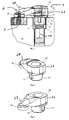
- the invention describes for fixing objects a clamping claw, which consists of two parts 10, 20.
- the first part, the clamping base 10 protrudes as leading part on a pad 40 in a matching recess 41 into it and is secured from twisting by its shape 11 (see below).
- On this clamping base 10 is a clamping finger 20 with its mounting leg 26 attached and secured by a bolt 30 on the base.
- the clamping leg 27 At the other end of the clamping finger 20, the clamping leg 27, this spans an object 50 in a recess 3 of a pad 40th
- This clamping base 10 takes place during clamping, by means of one of both parts protruding bolt 30, a movement in the axial direction of the bolt 30th or in the direction of the longitudinal axis 14 of the clamping base 10.
- This bolt 30 is guided or secured in the pad 40.
- This movement is limited as a special feature by a flange 12, which ultimately rests on the base 40. If through this limitation the End of the axial movement is reached, performs as another special Feature of the mounting leg 26 of the clamping finger 20 a transverse to Longitudinal axis 14 of the clamping base 10 lying lateral movement, until the desired clamping force is achieved by the bolt 30 finally.
- clamping finger 20 slides with the sliding surface 21 of the mounting leg 21 on the adapted sliding surface 13 of the clamping socket 10.
- the inventive Feature of these two sliding surfaces 21 and 13 is the successive adapted form and the expression as inclined plane. This sliding movement is again guided and limited by a special device 22. These Device 22 is here a stop.
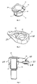
- Figures 2 and 3 show the clamping fingers 20 placed on the clamping base 10 with its shape 11, here an axially extending projection 11.
- a Pressure plate 23 is arranged, with which the article 50 on the pad 40 in the recess 3 is tensioned.
- the survey 28 can also directly on the clamping leg 27 of the clamping finger 20 may be arranged.
- This survey 28 or the cam on the clamping leg 27 of the clamping finger 20th is z. B. formed as a circular ring in an object 50 with a engages spherical or circular survey and this encompasses the survey.
- Figure 4 shows the clamping base 10 with its sliding surface 13, which formed as a slope is. On this sliding surface 13, the sliding surface 21 adapted thereto slides the attachment leg 26 of the clamping finger 20, see Figure 5. It is here clearly the first guide surface 24 of the particular device 22 of Figure 1 to see.
- FIG. 5 shows the clamping finger 20 from its underside. Here's the other side the particular device 22 of Figure 1 with its to the first guide surface 24 of the clamping base 10 adapted second guide surfaces 25 on the mounting leg 26 to see.
- FIG 6 is in a section the entire clamping claw with the clamping base 10 and the attached clamping finger 20 and with an engaging Bolt 30 is shown.
- the clamping base 10 and the clamping fingers 20 are on one Pad 40 secured by the bolt 30 (see Figure 1).
- This principle can be used, for example, in machining.
- Today's state of the art in the machining of metallic materials is the use of various carrier tools on which in as Insert seat called recess a cutting insert, referred to as indexable insert, made of hard and wear-resistant material is attached.
- This Cutting insert or indexable insert takes over by penetration into the Workpiece surface and a rotary and feed movement of tool and workpiece the actual material removal.
- the article 50 is therefore preferably a cutting plate made of a ceramic or tungsten carbide.
- the most important criterion in this cutting process is the correct, safe one and targeted attachment of the indexable insert by using a Clamping screw, a wedge or a clamping claw.
- a Clamping screw When using a Clamping is this usually by means of a screw, which by the clamping claw protrudes, immovably attached to the carrier tool.
- the fastening process If possible, it should be ensured that the reversible cutting plate fits snugly against the side walls of the insert seat.
- the advantage of this invention lies in the combination, the axial movement in Stretching over an inclined plane partially into a transversely acting movement convert.
Landscapes
- Engineering & Computer Science (AREA)
- Mechanical Engineering (AREA)
- Clamps And Clips (AREA)
- Jigs For Machine Tools (AREA)
Applications Claiming Priority (2)
| Application Number | Priority Date | Filing Date | Title |
|---|---|---|---|
| DE102004023570 | 2004-05-13 | ||
| DE102004023570 | 2004-05-13 |
Publications (2)
| Publication Number | Publication Date |
|---|---|
| EP1595648A2 true EP1595648A2 (fr) | 2005-11-16 |
| EP1595648A3 EP1595648A3 (fr) | 2009-05-27 |
Family
ID=34936293
Family Applications (1)
| Application Number | Title | Priority Date | Filing Date |
|---|---|---|---|
| EP05010050A Withdrawn EP1595648A3 (fr) | 2004-05-13 | 2005-05-09 | Bride de serrage en deux parties |
Country Status (2)
| Country | Link |
|---|---|
| US (1) | US7261496B2 (fr) |
| EP (1) | EP1595648A3 (fr) |
Cited By (2)
| Publication number | Priority date | Publication date | Assignee | Title |
|---|---|---|---|---|
| DE102008019955A1 (de) * | 2008-04-21 | 2009-10-22 | Kennametal Inc. | Werkzeughalter |
| WO2018172218A1 (fr) * | 2017-03-22 | 2018-09-27 | Ceramtec Gmbh | Système d'outil |
Families Citing this family (8)
| Publication number | Priority date | Publication date | Assignee | Title |
|---|---|---|---|---|
| US7547163B2 (en) * | 2007-07-16 | 2009-06-16 | Kennametal Inc. | Clamping tool holder |
| US8057131B2 (en) * | 2009-01-17 | 2011-11-15 | Kennametal Inc. | Clamping tool holder |
| CN101829983B (zh) * | 2009-03-10 | 2013-08-28 | 鸿富锦精密工业(深圳)有限公司 | 夹紧装置 |
| CN102348522A (zh) * | 2009-03-13 | 2012-02-08 | 特固克有限会社 | 用于刀片的刀架夹具组件及其压板 |
| US20110061502A1 (en) * | 2009-09-17 | 2011-03-17 | Chuan-Yi Liang | Lathe frame assembly |
| WO2011076835A1 (fr) * | 2009-12-22 | 2011-06-30 | Ceramtec Gmbh | Système de serrage |
| US9511421B2 (en) * | 2013-06-14 | 2016-12-06 | Kennametal Inc. | Cutting tool assembly having clamp assembly comprising a clamp and a coolant plate |
| US12544836B2 (en) * | 2022-02-25 | 2026-02-10 | Kennametal India Ltd. | Grooving tool with brazed carbide top clamp |
Family Cites Families (19)
| Publication number | Priority date | Publication date | Assignee | Title |
|---|---|---|---|---|
| FR959001A (fr) * | 1950-03-23 | |||
| DE1026594B (de) * | 1955-12-03 | 1958-03-20 | Friedrich Wilhelm Thienes | Spannklaue zum Aufspannen eines Werkstuecks auf den Tisch einer Werkzeugmaschine |
| GB1060906A (en) * | 1965-01-22 | 1967-03-08 | Charles Churchill & Company Lt | An improved tool holder for use in copying lathes |
| US3303553A (en) * | 1964-08-24 | 1967-02-14 | Viking Tool Company | Cutting tool assembly |
| GB1191063A (en) * | 1968-05-23 | 1970-05-06 | Rolls Royce | Tool Holder and Removable Cutting Insert |
| FR1587292A (fr) * | 1968-10-29 | 1970-03-13 | ||
| CH585082A5 (fr) * | 1974-09-30 | 1977-02-28 | Stellram Sa | |
| FR2332090A1 (fr) * | 1975-11-21 | 1977-06-17 | Plansee Metallwerk | Porte-outil, notamment pour tours a copier |
| DE7831988U1 (de) * | 1978-10-27 | 1980-04-03 | Komet Stahlhalter- Und Werkzeugfabrik Robert Breuning Gmbh, 7122 Besigheim | Klemmvorrichtung zur klemmung einer wendeschneidplatte an einem werkzeughalter |
| DE3002854A1 (de) * | 1980-01-26 | 1981-07-30 | Fried. Krupp Gmbh, 4300 Essen | Spanabhebendes werkzeug mit verstellbarem spanformer |
| DE3909238A1 (de) * | 1989-03-21 | 1990-09-27 | Feldmuehle Ag | Schneidwerkzeug fuer die spanabhebende bearbeitung |
| DE4033072A1 (de) * | 1990-10-18 | 1992-04-23 | Krupp Widia Gmbh | Schneidwerkzeug |
| SE509338C2 (sv) * | 1994-03-04 | 1999-01-11 | Sandvik Ab | Skärande verktyg |
| DE19524945A1 (de) * | 1995-07-08 | 1997-01-09 | Cerasiv Gmbh | Spanabhebendes Schneidwerkzeug |
| SE510851C2 (sv) * | 1996-12-23 | 1999-06-28 | Sandvik Ab | Skär samt hållare för skärande metallbearbetning |
| WO2000064615A1 (fr) * | 1999-04-26 | 2000-11-02 | Sandvik Aktiebolag | Porte-outil et plaque de serrage destines a recevoir une plaquette coupante |
| US7073986B2 (en) * | 2001-11-08 | 2006-07-11 | Kennametal Inc. | Dimpled insert with retaining clamp |
| US6773210B2 (en) * | 2002-10-28 | 2004-08-10 | Kennametal, Inc. | Clamp pin tool holder |
| SE525875C2 (sv) * | 2002-11-13 | 2005-05-17 | Sandvik Ab | Skär för skärverktyg med upphöjd övergångsyta |
-
2005
- 2005-05-09 EP EP05010050A patent/EP1595648A3/fr not_active Withdrawn
- 2005-05-10 US US11/125,825 patent/US7261496B2/en not_active Expired - Fee Related
Cited By (4)
| Publication number | Priority date | Publication date | Assignee | Title |
|---|---|---|---|---|
| DE102008019955A1 (de) * | 2008-04-21 | 2009-10-22 | Kennametal Inc. | Werkzeughalter |
| WO2018172218A1 (fr) * | 2017-03-22 | 2018-09-27 | Ceramtec Gmbh | Système d'outil |
| CN110430956A (zh) * | 2017-03-22 | 2019-11-08 | 陶瓷技术有限责任公司 | 工具系统 |
| US11504777B2 (en) | 2017-03-22 | 2022-11-22 | Ceramtec Gmbh | Tool system |
Also Published As
| Publication number | Publication date |
|---|---|
| EP1595648A3 (fr) | 2009-05-27 |
| US7261496B2 (en) | 2007-08-28 |
| US20050253319A1 (en) | 2005-11-17 |
Similar Documents
| Publication | Publication Date | Title |
|---|---|---|
| DE19947840B4 (de) | Keilfreier Sägeblatt-Klemm-Mechanismus | |
| DE69818247T2 (de) | Winkeleinstellbares anfaswerkzeug | |
| DE60021085T2 (de) | Werkzeughalter und spannplatte für einen schneideinsatz | |
| EP2226145B1 (fr) | Dispositif de serrage | |
| EP3075477B1 (fr) | Outil de fraisage et élément de coupe utilisé dans un outil de fraisage | |
| DE3804270A1 (de) | Mehrfach-spannvorrichtung | |
| EP1595648A2 (fr) | Bride de serrage en deux parties | |
| DE3517033C1 (de) | Universalhalter | |
| EP2922651A1 (fr) | Outil d'usinage par enlèvement de copeaux | |
| DE3007322C2 (de) | Schneidwerkzeug zur spanabhebenden Bearbeitung | |
| DE102004008624B4 (de) | Aufnahmevorrichtung einer Meßeinrichtung | |
| DE102016200195A1 (de) | Schneidplatte mit einer Mulde | |
| EP0354879A2 (fr) | Moyen de serrage rapide | |
| DE4037984C2 (de) | Kreissägeblatt mit auswechselbaren und einstellbaren Schneidplatten | |
| DE4233492A1 (de) | Werkstock zur Mehrfachbearbeitung auf einer Werkbank | |
| DE102005021369A1 (de) | Zweigeteilte Spannpratze | |
| DE102016205658B3 (de) | Schneidwerkzeug mit einem an einem trägerkörper durch eine spannpratze lösbar befestigtem schneidkörper | |
| EP3702100B1 (fr) | Dispositif de butée | |
| DE4419668C1 (de) | Fräswerkzeug | |
| DE4216763C2 (de) | Kopier-Drechselgerät | |
| EP1262262A1 (fr) | Barre d'alésage | |
| WO2008064656A1 (fr) | Outil d'usinage à enlèvement de copeaux | |
| DE102005011955A1 (de) | Spannpratze mit Wechselfunktion,Schneidwerkzeug und Schneidplattenset | |
| DE3307727A1 (de) | Werkzeug zum bohren von bohrungen in werkstuecken | |
| DE20017808U1 (de) | Werkzeugaufnahme für einen Speicherplatz eines Werkzeugmagazines |
Legal Events
| Date | Code | Title | Description |
|---|---|---|---|
| PUAI | Public reference made under article 153(3) epc to a published international application that has entered the european phase |
Free format text: ORIGINAL CODE: 0009012 |
|
| AK | Designated contracting states |
Kind code of ref document: A2 Designated state(s): AT BE BG CH CY CZ DE DK EE ES FI FR GB GR HU IE IS IT LI LT LU MC NL PL PT RO SE SI SK TR |
|
| AX | Request for extension of the european patent |
Extension state: AL BA HR LV MK YU |
|
| RAP1 | Party data changed (applicant data changed or rights of an application transferred) |
Owner name: CERAMTEC AG |
|
| PUAL | Search report despatched |
Free format text: ORIGINAL CODE: 0009013 |
|
| AK | Designated contracting states |
Kind code of ref document: A3 Designated state(s): AT BE BG CH CY CZ DE DK EE ES FI FR GB GR HU IE IS IT LI LT LU MC NL PL PT RO SE SI SK TR |
|
| AX | Request for extension of the european patent |
Extension state: AL BA HR LV MK YU |
|
| 17P | Request for examination filed |
Effective date: 20091127 |
|
| AKX | Designation fees paid |
Designated state(s): AT BE BG CH CY CZ DE DK EE ES FI FR GB GR HU IE IS IT LI LT LU MC NL PL PT RO SE SI SK TR |
|
| 17Q | First examination report despatched |
Effective date: 20100414 |
|
| RAP1 | Party data changed (applicant data changed or rights of an application transferred) |
Owner name: CERAMTEC GMBH |
|
| STAA | Information on the status of an ep patent application or granted ep patent |
Free format text: STATUS: THE APPLICATION IS DEEMED TO BE WITHDRAWN |
|
| 18D | Application deemed to be withdrawn |
Effective date: 20170201 |
|
| RIC1 | Information provided on ipc code assigned before grant |
Ipc: B23B 27/16 20060101ALI20050826BHEP Ipc: B25B 5/10 20060101AFI20050826BHEP |