EP1595679A1 - Dispositif de support pour moule à canal chauffé et moule à canal chauffé - Google Patents
Dispositif de support pour moule à canal chauffé et moule à canal chauffé Download PDFInfo
- Publication number
- EP1595679A1 EP1595679A1 EP05007260A EP05007260A EP1595679A1 EP 1595679 A1 EP1595679 A1 EP 1595679A1 EP 05007260 A EP05007260 A EP 05007260A EP 05007260 A EP05007260 A EP 05007260A EP 1595679 A1 EP1595679 A1 EP 1595679A1
- Authority
- EP
- European Patent Office
- Prior art keywords
- hot runner
- support device
- plate
- nozzle needle
- support
- Prior art date
- Legal status (The legal status is an assumption and is not a legal conclusion. Google has not performed a legal analysis and makes no representation as to the accuracy of the status listed.)
- Granted
Links
Images


Classifications
-
- B—PERFORMING OPERATIONS; TRANSPORTING
- B29—WORKING OF PLASTICS; WORKING OF SUBSTANCES IN A PLASTIC STATE IN GENERAL
- B29C—SHAPING OR JOINING OF PLASTICS; SHAPING OF MATERIAL IN A PLASTIC STATE, NOT OTHERWISE PROVIDED FOR; AFTER-TREATMENT OF THE SHAPED PRODUCTS, e.g. REPAIRING
- B29C45/00—Injection moulding, i.e. forcing the required volume of moulding material through a nozzle into a closed mould; Apparatus therefor
- B29C45/17—Component parts, details or accessories; Auxiliary operations
- B29C45/26—Moulds
- B29C45/27—Sprue channels ; Runner channels or runner nozzles
- B29C45/28—Closure devices therefor
- B29C45/2806—Closure devices therefor consisting of needle valve systems
-
- B—PERFORMING OPERATIONS; TRANSPORTING
- B29—WORKING OF PLASTICS; WORKING OF SUBSTANCES IN A PLASTIC STATE IN GENERAL
- B29C—SHAPING OR JOINING OF PLASTICS; SHAPING OF MATERIAL IN A PLASTIC STATE, NOT OTHERWISE PROVIDED FOR; AFTER-TREATMENT OF THE SHAPED PRODUCTS, e.g. REPAIRING
- B29C45/00—Injection moulding, i.e. forcing the required volume of moulding material through a nozzle into a closed mould; Apparatus therefor
- B29C45/17—Component parts, details or accessories; Auxiliary operations
- B29C45/26—Moulds
- B29C45/27—Sprue channels ; Runner channels or runner nozzles
- B29C45/28—Closure devices therefor
- B29C45/2806—Closure devices therefor consisting of needle valve systems
- B29C2045/2889—Sealing guide bushings therefor
Definitions
- the invention relates to a supporting device for supporting the drive cylinder plate on the hot runner plate of a hot runner mold for spraying a plastic molding according to the preamble of the claim 1 and a tool equipped therewith according to the preamble of claim 17.
- a hot runner tool of the type in question for spraying a Plastic molding initially has a mold cavity, in which the sprayable plastic is injected.
- the mold nest is with at least a nozzle-like Anspritzö réelle provided by a nozzle needle can be opened and closed.
- the sprayable plastic is doing about at least one channel, which is essentially in one heated hot runner plate runs, led to Anspritzö réelle.
- a hot runner tool which is a drive cylinder plate has, which is arranged at a distance from the hot runner plate and itself supported by a support member on the hot runner plate. It will be both the hot runner plate and the support member from the nozzle needle penetrated. With your pointing away from the Anspritzö réelle end the nozzle needle is connected to a piston-like drive, which in the drive cylinder plate is provided.
- a disadvantage of this known Arrangement is in particular that on the one hand in the thermally induced Extension of the hot runner plate, the nozzle needle deformation on the other hand, a leakage of plasticized or molten plastic through the nozzle needle channel in the area of the nozzle needle drive can not be excluded, resulting in in particular a malfunction of the nozzle needle drive and thus a failure of the tool altogether.
- Each nozzle needle can have its own support element be associated with one recess or more Nozzle needles pass through one or more recesses in one Support element.
- At least one of the nozzle needle is substantially provided sealingly encompassing sealing element, with radial play and in particular radially movable and axially substantially fixed in the recess of the support element is arranged.
- sealing element With radial play and in particular radially movable and axially substantially fixed in the recess of the support element is arranged.
- the shape of the support element is basically arbitrary, as long as for a sufficient support of the drive cylinder plate on the Hot runner plate and on the other hand, the above-described radially movable storage of the sealing element is ensured.
- the support element has an in essential cup-like shape with a bottom and a bottom in the essentially closed or interrupted circumferential frame, wherein the continuous recess in the bottom of the support element is arranged.
- the support element is preferably in the Tool arranged that it is in the area of its bottom at the hot runner plate abuts or rests against this and collar side of the drive cylinder plate comes to the plant.
- the support member may, for example, in plan view rectangular, square, be polygon or the like. Preferably, however, this has Supporting a substantially circular or circular cylindrical Build up.
- the shape of the recess is initially also basically arbitrary.
- the through recess has an in essential circular shape.
- the support device can be loose between the Drive cylinder plate and the hot runner plate may be arranged.
- the Support element means for releasably securing the support element to the Hot runner plate or the drive cylinder plate on. These funds can formed for example in the simplest case by fastening screws become. This means that the supporting device or the supporting element firmly attached to the hot runner plate or the drive cylinder plate is while storing on the opposite drive cylinder plate or hot runner plate in or parallel to each plate plane floating or movable takes place.
- the hot runner plate facing surface of the bottom of the support element at least partially designed as a sealing surface, which at the drive cylinder plate facing surface of the hot runner plate substantially sealing to Plant can be brought.
- a heel-like the continuous recess substantially completely annular embracing depression educated.
- the shape of the sealing element is basically arbitrary, as long as for a the desired sealing effect at least on the nozzle needle and on the other hand, the position fixation described above in the support element is secured.
- the sealing element is disc or is socket-shaped and has an outer diameter, which is at least slightly smaller than the inner diameter of through recess.
- the sealing element a collar-like approach whose outer diameter is greater than the Inner diameter of the recess and at least slightly smaller than the diameter of the annular recess. This will be in easy way, the axial fixation of the sealing element at the same time radial mobility ensured.
- the Height of the collar-like approach at least slightly smaller than that Depth of the annular recess. In other words, this means that in the axial direction, the sealing element between the support element and Hot runner plate is mounted in the manner of a clearance.
- Hot runner plate facing surface of the sealing element at least partially designed as a sealing surface. This allows the sealing element not only with respect to the nozzle needle, but also with respect to the hot runner plate act sealing.
- a particularly preferred embodiment of the invention is in the hot runner plate facing surfaces of the sealing element and / or the support element in each case at least one drainage channel provided such that a targeted leakage connection between the Nozzle needle and the between the drive cylinder plate and the hot runner plate provided space is formed.
- This can on the one hand be ensured that no plasticized or molten Plastic material in the axial direction through the sealing element in the Area of the nozzle needle drive occurs, and on the other hand that eventually through the channel in the hot runner plate in which the nozzle needle runs, leaking plastic material is discharged into an area in which does not disturb such contamination and / or easily if necessary can be removed.
- these drainage channels are substantially arranged radially to the nozzle needle axis and the associated Drainage channels of sealing element and support element are substantially aligned.
- the derivative of leaking plastic material be improved.
- a plurality of Drainage channels arranged substantially cross or star shape be.
- the support element consists of a material poor thermal conduction properties, in particular of titanium, a titanium alloy or made of Cr-steel. This can cause unwanted heat transfer between the hot runner plate and the drive cylinder plate be minimized.
- the material of the sealing element is initially arbitrary, as long as a sufficient sealing effect can be achieved.
- they are basically Elastomer seals conceivable.
- the sealing element is preferably substantially made of steel, in particular the same steel as the nozzle needle.
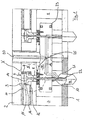
- the tool shown in Fig. 1 has a frame-like structure with a base plate 1, a cover plate 2 and side plates 3 and 4 on.
- a drive cylinder plate 5 provided with a cylindrical step-shaped recess 6 with a region 7 of larger diameter and a region 8 smaller Diameter has.
- an im Cross-section stepped piston 9 slidably.
- a Nozzle needle 10 is fastened such that upon movement of the piston 9 in Direction of the arrow F, the nozzle needle 10 in the direction of its longitudinal axis is moved.
- the piston plate 14 is at its periphery with a in an annular groove 15 arranged sealing ring 16 is provided.
- a fluidic medium for example Compressed air or hydraulic oil
- the Hot runner plate 18 In the space below the drive cylinder plate 5 is a hot runner plate 18 arranged substantially parallel to the drive cylinder plate 5.
- the Hot runner plate 18 has a channel 19 for supplying the plasticized or molten plastic.
- the channel 19 is at his first end 20 with a device, not shown, for melting connected to the plastic and opens with his second End 21 in the nozzle channel 22, which is substantially in a nozzle body 24 is arranged and turn into an unillustrated mold nest empties.
- To freeze the supplied plastic material in the Hot runner plate 18 is to prevent hot runner plate with a Heating device 23 provided.
- the support device 25 for supporting the drive cylinder plate. 5 arranged on the hot runner plate 18.
- the support device has a support member 26 and a Sealing element 27 on.
- the support member 26 has a cross-section in the essentially pot-shaped or cup-shaped circular cylindrical shape with a Floor 28 and a collar-shaped closed frame 29 on.
- By means of two fastening screws 30, 31 is the support member 26th attached to the hot runner plate 18 such that the bottom 28 becomes the hot runner plate 18 and the collar of the frame 29 to the drive cylinder plate. 5 points and there each comes to the plant.
- the bottom 28 of the Support member 26 is a continuous substantially circular Recess 32 provided.
- Surface 33 of the bottom 28 is a circular recess 34 provided, which surrounds the recess 32 concentrically and annularly.
- the sealing element 27 has a bush-shaped main body 35, the at its facing the hot runner plate 18 end with a collar-like Approach 36 is provided.
- the sealing element 27 encloses in the essentially radial sealing the nozzle needle 22, wherein, however Nozzle needle 22 in the axial direction in the sealing element 27 substantially is freely movable.
- the outer diameter of the bush-shaped main body 35 of the sealing element 27 at least slightly smaller than that Diameter of the recess 32 and the outer diameter of the collar-like Approach 36 of the sealing element is at least slightly smaller as the diameter of the recess 34.
- the axial height of the collar-like Neck 36 is also slightly smaller than the depth of the depression 34, so that the sealing element 27 in the manner of a clearance between the support member 26 and the surface of the hot runner plate 18 in Radial direction at least slightly movable, in the axial direction but essentially fixed, held.
- the nozzle needle passes through the hot runner plate 18 in a recess 37 with at least little radial play.
- the support element 26 and the sealing element 27 in its direction to the hot runner plate 18 Surface each have a drainage channel 38 and 39, wherein the drainage channel 38 from the nozzle needle 22 to the annular gap 40 and the drainage channel 39 from the annular gap 40 extends radially outward.
- the two Drainage channels 38 and 39 are substantially aligned. If so plasticized or molten plastic material through the recess 37 in the hot runner plate 18 in the range of the invention Support device 25 passes, this is through the drainage channels radially outward into the space between the hot runner plate 18 and the Drive cylinder plate 5 out in such a way that no plastic material can penetrate into the area of the drive.
- the effect Sealing surfaces between sealing element 27, hot runner plate 28 and support element 26 together in the manner of a labyrinth seal.
- FIG. 4 of an inventive Support basically has the same structure as that in FIGS. 1 to 3 illustrated embodiment. That's it Support member 41, however, with two through recesses 42nd provided, in each of which a sealing element 43 is arranged, the of each of a nozzle needle 44 is penetrated.
Landscapes
- Engineering & Computer Science (AREA)
- Manufacturing & Machinery (AREA)
- Mechanical Engineering (AREA)
- Moulds For Moulding Plastics Or The Like (AREA)
- Injection Moulding Of Plastics Or The Like (AREA)
Applications Claiming Priority (3)
| Application Number | Priority Date | Filing Date | Title |
|---|---|---|---|
| DE102004022036A DE102004022036B3 (de) | 2004-05-03 | 2004-05-03 | Abstützvorrichtung für ein Nadelverschluß-Heißkanalwerkzeug |
| DE102004022036 | 2004-05-03 | ||
| DE202004007135U DE202004007135U1 (de) | 2004-05-03 | 2004-05-03 | Abstützvorrichtung |
Publications (2)
| Publication Number | Publication Date |
|---|---|
| EP1595679A1 true EP1595679A1 (fr) | 2005-11-16 |
| EP1595679B1 EP1595679B1 (fr) | 2008-03-19 |
Family
ID=38894061
Family Applications (1)
| Application Number | Title | Priority Date | Filing Date |
|---|---|---|---|
| EP05007260A Expired - Lifetime EP1595679B1 (fr) | 2004-05-03 | 2005-04-04 | Dispositif de support pour moule à canal chauffé et moule à canal chauffé |
Country Status (2)
| Country | Link |
|---|---|
| EP (1) | EP1595679B1 (fr) |
| DE (2) | DE102004022036B3 (fr) |
Cited By (2)
| Publication number | Priority date | Publication date | Assignee | Title |
|---|---|---|---|---|
| US7407380B2 (en) | 2005-02-04 | 2008-08-05 | Mold-Masters (2007) Limited | Valve pin bushing with vent channels for an injection molding apparatus |
| CN114131852A (zh) * | 2021-11-22 | 2022-03-04 | 临海伟星新型建材有限公司 | 一种热流道板及其使用方法 |
Families Citing this family (11)
| Publication number | Priority date | Publication date | Assignee | Title |
|---|---|---|---|---|
| ITRM20040107A1 (it) | 2004-03-02 | 2004-06-02 | Sipa Societa Industrializzazio | Dispositivo e metodo di condizionamento di oggetti in plastica. |
| ITRM20040163A1 (it) | 2004-03-30 | 2004-06-30 | Sipa Societa Industrializzazio | Apparato di stampaggio per soffiaggio di oggetti in plastica. |
| DE102004022036B3 (de) * | 2004-05-03 | 2005-07-07 | Heitec-Heisskanaltechnik Gmbh | Abstützvorrichtung für ein Nadelverschluß-Heißkanalwerkzeug |
| DE102005028100A1 (de) * | 2005-06-16 | 2006-12-21 | Günther Heißkanaltechnik GmbH | Reinigungsvorrichtung zur Verwendung in Spritzgießvorrichtungen und Spritzgießvorrichtung |
| ITRM20050430A1 (it) | 2005-08-05 | 2007-02-06 | Sipa Societa Industrializzazio | Sistema di iniezione. |
| US20070119504A1 (en) * | 2005-11-28 | 2007-05-31 | Yudo Co. Ltd. | Heat dissipating apparatus for cylinders of injection molding machines |
| DE202006008744U1 (de) * | 2006-05-31 | 2007-10-11 | Günther Heisskanaltechnik Gmbh | Spritzgießvorrichtung |
| DE102008026408B4 (de) * | 2007-06-08 | 2021-02-11 | Mold-Masters (2007) Limited | Spritzgießapparat und mehrteilige Ventilstiftbuchse |
| EP2200799A4 (fr) | 2007-10-22 | 2012-08-29 | Mold Masters 2007 Ltd | Dispositif de moulage par injection |
| CN102371654A (zh) * | 2010-08-17 | 2012-03-14 | 於岩君 | 针阀式热流道模具的阀针密封装置 |
| CN103213247B (zh) * | 2012-01-18 | 2016-12-14 | 上海瀚典热流道科技有限公司 | 多点针阀 |
Citations (3)
| Publication number | Priority date | Publication date | Assignee | Title |
|---|---|---|---|---|
| EP0021273A1 (fr) * | 1979-06-12 | 1981-01-07 | Hendrikus Jacobus Elisabeth Schouenberg | Mécanisme d'injection pour mouler des matières plastiques |
| EP0407683A2 (fr) * | 1989-07-14 | 1991-01-16 | Mold-Masters Limited | Mécanisme d'actionnement pneumatique pour le moulage par injection |
| DE202004007135U1 (de) * | 2004-05-03 | 2004-08-05 | Heitec-Heisskanaltechnik Gmbh | Abstützvorrichtung |
-
2004
- 2004-05-03 DE DE102004022036A patent/DE102004022036B3/de not_active Expired - Fee Related
- 2004-05-03 DE DE202004007135U patent/DE202004007135U1/de not_active Expired - Lifetime
-
2005
- 2005-04-04 EP EP05007260A patent/EP1595679B1/fr not_active Expired - Lifetime
Patent Citations (3)
| Publication number | Priority date | Publication date | Assignee | Title |
|---|---|---|---|---|
| EP0021273A1 (fr) * | 1979-06-12 | 1981-01-07 | Hendrikus Jacobus Elisabeth Schouenberg | Mécanisme d'injection pour mouler des matières plastiques |
| EP0407683A2 (fr) * | 1989-07-14 | 1991-01-16 | Mold-Masters Limited | Mécanisme d'actionnement pneumatique pour le moulage par injection |
| DE202004007135U1 (de) * | 2004-05-03 | 2004-08-05 | Heitec-Heisskanaltechnik Gmbh | Abstützvorrichtung |
Cited By (2)
| Publication number | Priority date | Publication date | Assignee | Title |
|---|---|---|---|---|
| US7407380B2 (en) | 2005-02-04 | 2008-08-05 | Mold-Masters (2007) Limited | Valve pin bushing with vent channels for an injection molding apparatus |
| CN114131852A (zh) * | 2021-11-22 | 2022-03-04 | 临海伟星新型建材有限公司 | 一种热流道板及其使用方法 |
Also Published As
| Publication number | Publication date |
|---|---|
| EP1595679B1 (fr) | 2008-03-19 |
| DE202004007135U1 (de) | 2004-08-05 |
| DE102004022036B3 (de) | 2005-07-07 |
Similar Documents
| Publication | Publication Date | Title |
|---|---|---|
| DE102004022036B3 (de) | Abstützvorrichtung für ein Nadelverschluß-Heißkanalwerkzeug | |
| DE102008051202A1 (de) | Spritzgießdüse | |
| EP1524091B1 (fr) | Dispositif pour surmouler en particulier des pièces en matière plastique | |
| DE2539785B2 (de) | Heißkanalspritzdüse | |
| WO2008040415A1 (fr) | Dispositif de moulage par injection pourvu de buses avec obturateur à aiguille disposées dos à dos | |
| DE4014244C2 (fr) | ||
| EP0925902B1 (fr) | Moule d'injection | |
| EP3231574B1 (fr) | Douille de guidage pour un dispositif de moulage par injection | |
| DE3336203A1 (de) | Spritzgiess- oder presswerkzeug zur verarbeitung von kunststoffmassen | |
| WO2007017187A1 (fr) | Dispositif de moulage par injection dote d'une douille d'obturateur a aiguille et d'une douille de guidage | |
| WO2009062669A2 (fr) | Buse de moulage par injection | |
| DE202006018031U1 (de) | Anordnung zum Verschließen von Kanalabschnitten in einem Heiß- oder Kaltkanalverteiler | |
| WO2007098798A1 (fr) | Dispositif de moulage par injection dote d'une tuyere fermee par pointeau | |
| AT524876B1 (de) | Absperrdüse mit Nadelventil, Einspritzvorrichtung und Spritzgießmaschine | |
| EP1410892B1 (fr) | Moule à canaux chauds avec un appareil pour ouvrir et fermer des buses d'injection | |
| EP4429857A1 (fr) | Tête de mélange et procédé de fabrication d'une tête de mélange | |
| EP2860012B1 (fr) | Douille d'équilibrage de la température, de préférence pour des outils de moulage par injection en plastique | |
| DE4109122C1 (fr) | ||
| WO2008040647A1 (fr) | Buse d'alimentation de décompression et buse de machine de décompression | |
| DE19634958C2 (de) | Zylinderkopfhaube | |
| DE10321355A1 (de) | Düse | |
| DE102011050976A1 (de) | Auswerfvorrichtung und Werkzeug mit einer derartigen Auswerfvorrichtung | |
| WO2007137648A1 (fr) | Dispositif de moulage par injection avec buse d'obturation à aiguille et canal de drainage | |
| EP3339703B1 (fr) | Soupape à tiroir pourvue de canal | |
| EP0962295A2 (fr) | Moule d'injection |
Legal Events
| Date | Code | Title | Description |
|---|---|---|---|
| PUAI | Public reference made under article 153(3) epc to a published international application that has entered the european phase |
Free format text: ORIGINAL CODE: 0009012 |
|
| 17P | Request for examination filed |
Effective date: 20050818 |
|
| AK | Designated contracting states |
Kind code of ref document: A1 Designated state(s): AT BE BG CH CY CZ DE DK EE ES FI FR GB GR HU IE IS IT LI LT LU MC NL PL PT RO SE SI SK TR |
|
| AX | Request for extension of the european patent |
Extension state: AL BA HR LV MK YU |
|
| AKX | Designation fees paid |
Designated state(s): DE FR GB |
|
| GRAP | Despatch of communication of intention to grant a patent |
Free format text: ORIGINAL CODE: EPIDOSNIGR1 |
|
| GRAS | Grant fee paid |
Free format text: ORIGINAL CODE: EPIDOSNIGR3 |
|
| GRAA | (expected) grant |
Free format text: ORIGINAL CODE: 0009210 |
|
| AK | Designated contracting states |
Kind code of ref document: B1 Designated state(s): DE FR GB |
|
| REG | Reference to a national code |
Ref country code: GB Ref legal event code: FG4D Free format text: NOT ENGLISH |
|
| REF | Corresponds to: |
Ref document number: 502005003266 Country of ref document: DE Date of ref document: 20080430 Kind code of ref document: P |
|
| ET | Fr: translation filed | ||
| PLBE | No opposition filed within time limit |
Free format text: ORIGINAL CODE: 0009261 |
|
| STAA | Information on the status of an ep patent application or granted ep patent |
Free format text: STATUS: NO OPPOSITION FILED WITHIN TIME LIMIT |
|
| 26N | No opposition filed |
Effective date: 20081222 |
|
| PGFP | Annual fee paid to national office [announced via postgrant information from national office to epo] |
Ref country code: DE Payment date: 20120621 Year of fee payment: 8 |
|
| PGFP | Annual fee paid to national office [announced via postgrant information from national office to epo] |
Ref country code: GB Payment date: 20120423 Year of fee payment: 8 Ref country code: FR Payment date: 20120511 Year of fee payment: 8 |
|
| GBPC | Gb: european patent ceased through non-payment of renewal fee |
Effective date: 20130404 |
|
| PG25 | Lapsed in a contracting state [announced via postgrant information from national office to epo] |
Ref country code: GB Free format text: LAPSE BECAUSE OF NON-PAYMENT OF DUE FEES Effective date: 20130404 Ref country code: DE Free format text: LAPSE BECAUSE OF NON-PAYMENT OF DUE FEES Effective date: 20131101 |
|
| REG | Reference to a national code |
Ref country code: FR Ref legal event code: ST Effective date: 20131231 |
|
| REG | Reference to a national code |
Ref country code: DE Ref legal event code: R119 Ref document number: 502005003266 Country of ref document: DE Effective date: 20131101 |
|
| PG25 | Lapsed in a contracting state [announced via postgrant information from national office to epo] |
Ref country code: FR Free format text: LAPSE BECAUSE OF NON-PAYMENT OF DUE FEES Effective date: 20130430 |