EP1595740B1 - Scheinwerfereinheit für ein Fahrzeug und Verfahren zum adaptiven Ausleuchten einer Fahrstrecke - Google Patents
Scheinwerfereinheit für ein Fahrzeug und Verfahren zum adaptiven Ausleuchten einer Fahrstrecke Download PDFInfo
- Publication number
- EP1595740B1 EP1595740B1 EP05009927A EP05009927A EP1595740B1 EP 1595740 B1 EP1595740 B1 EP 1595740B1 EP 05009927 A EP05009927 A EP 05009927A EP 05009927 A EP05009927 A EP 05009927A EP 1595740 B1 EP1595740 B1 EP 1595740B1
- Authority
- EP
- European Patent Office
- Prior art keywords
- light
- modules
- pivoting
- headlamp unit
- axis
- Prior art date
- Legal status (The legal status is an assumption and is not a legal conclusion. Google has not performed a legal analysis and makes no representation as to the accuracy of the status listed.)
- Expired - Lifetime
Links
- 238000000034 method Methods 0.000 title claims abstract description 15
- 238000005286 illumination Methods 0.000 claims description 11
- 230000008878 coupling Effects 0.000 claims description 7
- 238000010168 coupling process Methods 0.000 claims description 7
- 238000005859 coupling reaction Methods 0.000 claims description 7
- 230000002411 adverse Effects 0.000 claims 2
- 230000003044 adaptive effect Effects 0.000 abstract 1
- 230000001419 dependent effect Effects 0.000 description 1
- 238000012986 modification Methods 0.000 description 1
- 230000004048 modification Effects 0.000 description 1
- 238000004804 winding Methods 0.000 description 1
Images

Classifications
-
- B—PERFORMING OPERATIONS; TRANSPORTING
- B60—VEHICLES IN GENERAL
- B60Q—ARRANGEMENT OF SIGNALLING OR LIGHTING DEVICES, THE MOUNTING OR SUPPORTING THEREOF OR CIRCUITS THEREFOR, FOR VEHICLES IN GENERAL
- B60Q1/00—Arrangement of optical signalling or lighting devices, the mounting or supporting thereof or circuits therefor
- B60Q1/0029—Spatial arrangement
- B60Q1/0041—Spatial arrangement of several lamps in relation to each other
-
- B—PERFORMING OPERATIONS; TRANSPORTING
- B60—VEHICLES IN GENERAL
- B60Q—ARRANGEMENT OF SIGNALLING OR LIGHTING DEVICES, THE MOUNTING OR SUPPORTING THEREOF OR CIRCUITS THEREFOR, FOR VEHICLES IN GENERAL
- B60Q1/00—Arrangement of optical signalling or lighting devices, the mounting or supporting thereof or circuits therefor
- B60Q1/02—Arrangement of optical signalling or lighting devices, the mounting or supporting thereof or circuits therefor the devices being primarily intended to illuminate the way ahead or to illuminate other areas of way or environments
- B60Q1/04—Arrangement of optical signalling or lighting devices, the mounting or supporting thereof or circuits therefor the devices being primarily intended to illuminate the way ahead or to illuminate other areas of way or environments the devices being headlights
- B60Q1/06—Arrangement of optical signalling or lighting devices, the mounting or supporting thereof or circuits therefor the devices being primarily intended to illuminate the way ahead or to illuminate other areas of way or environments the devices being headlights adjustable, e.g. remotely-controlled from inside vehicle
-
- B—PERFORMING OPERATIONS; TRANSPORTING
- B60—VEHICLES IN GENERAL
- B60Q—ARRANGEMENT OF SIGNALLING OR LIGHTING DEVICES, THE MOUNTING OR SUPPORTING THEREOF OR CIRCUITS THEREFOR, FOR VEHICLES IN GENERAL
- B60Q1/00—Arrangement of optical signalling or lighting devices, the mounting or supporting thereof or circuits therefor
- B60Q1/02—Arrangement of optical signalling or lighting devices, the mounting or supporting thereof or circuits therefor the devices being primarily intended to illuminate the way ahead or to illuminate other areas of way or environments
- B60Q1/04—Arrangement of optical signalling or lighting devices, the mounting or supporting thereof or circuits therefor the devices being primarily intended to illuminate the way ahead or to illuminate other areas of way or environments the devices being headlights
- B60Q1/06—Arrangement of optical signalling or lighting devices, the mounting or supporting thereof or circuits therefor the devices being primarily intended to illuminate the way ahead or to illuminate other areas of way or environments the devices being headlights adjustable, e.g. remotely-controlled from inside vehicle
- B60Q1/08—Arrangement of optical signalling or lighting devices, the mounting or supporting thereof or circuits therefor the devices being primarily intended to illuminate the way ahead or to illuminate other areas of way or environments the devices being headlights adjustable, e.g. remotely-controlled from inside vehicle automatically
- B60Q1/12—Arrangement of optical signalling or lighting devices, the mounting or supporting thereof or circuits therefor the devices being primarily intended to illuminate the way ahead or to illuminate other areas of way or environments the devices being headlights adjustable, e.g. remotely-controlled from inside vehicle automatically due to steering position
-
- B—PERFORMING OPERATIONS; TRANSPORTING
- B60—VEHICLES IN GENERAL
- B60Q—ARRANGEMENT OF SIGNALLING OR LIGHTING DEVICES, THE MOUNTING OR SUPPORTING THEREOF OR CIRCUITS THEREFOR, FOR VEHICLES IN GENERAL
- B60Q1/00—Arrangement of optical signalling or lighting devices, the mounting or supporting thereof or circuits therefor
- B60Q1/02—Arrangement of optical signalling or lighting devices, the mounting or supporting thereof or circuits therefor the devices being primarily intended to illuminate the way ahead or to illuminate other areas of way or environments
- B60Q1/04—Arrangement of optical signalling or lighting devices, the mounting or supporting thereof or circuits therefor the devices being primarily intended to illuminate the way ahead or to illuminate other areas of way or environments the devices being headlights
- B60Q1/18—Arrangement of optical signalling or lighting devices, the mounting or supporting thereof or circuits therefor the devices being primarily intended to illuminate the way ahead or to illuminate other areas of way or environments the devices being headlights being additional front lights
-
- B—PERFORMING OPERATIONS; TRANSPORTING
- B60—VEHICLES IN GENERAL
- B60Q—ARRANGEMENT OF SIGNALLING OR LIGHTING DEVICES, THE MOUNTING OR SUPPORTING THEREOF OR CIRCUITS THEREFOR, FOR VEHICLES IN GENERAL
- B60Q2300/00—Indexing codes for automatically adjustable headlamps or automatically dimmable headlamps
- B60Q2300/30—Indexing codes relating to the vehicle environment
- B60Q2300/31—Atmospheric conditions
- B60Q2300/312—Adverse weather
-
- B—PERFORMING OPERATIONS; TRANSPORTING
- B60—VEHICLES IN GENERAL
- B60Q—ARRANGEMENT OF SIGNALLING OR LIGHTING DEVICES, THE MOUNTING OR SUPPORTING THEREOF OR CIRCUITS THEREFOR, FOR VEHICLES IN GENERAL
- B60Q2300/00—Indexing codes for automatically adjustable headlamps or automatically dimmable headlamps
- B60Q2300/30—Indexing codes relating to the vehicle environment
- B60Q2300/32—Road surface or travel path
- B60Q2300/322—Road curvature
-
- B—PERFORMING OPERATIONS; TRANSPORTING
- B60—VEHICLES IN GENERAL
- B60Q—ARRANGEMENT OF SIGNALLING OR LIGHTING DEVICES, THE MOUNTING OR SUPPORTING THEREOF OR CIRCUITS THEREFOR, FOR VEHICLES IN GENERAL
- B60Q2300/00—Indexing codes for automatically adjustable headlamps or automatically dimmable headlamps
- B60Q2300/30—Indexing codes relating to the vehicle environment
- B60Q2300/33—Driving situation
- B60Q2300/332—Driving situation on city roads
-
- B—PERFORMING OPERATIONS; TRANSPORTING
- B60—VEHICLES IN GENERAL
- B60Q—ARRANGEMENT OF SIGNALLING OR LIGHTING DEVICES, THE MOUNTING OR SUPPORTING THEREOF OR CIRCUITS THEREFOR, FOR VEHICLES IN GENERAL
- B60Q2300/00—Indexing codes for automatically adjustable headlamps or automatically dimmable headlamps
- B60Q2300/30—Indexing codes relating to the vehicle environment
- B60Q2300/33—Driving situation
- B60Q2300/333—Driving situation on suburban or country roads
-
- B—PERFORMING OPERATIONS; TRANSPORTING
- B60—VEHICLES IN GENERAL
- B60Q—ARRANGEMENT OF SIGNALLING OR LIGHTING DEVICES, THE MOUNTING OR SUPPORTING THEREOF OR CIRCUITS THEREFOR, FOR VEHICLES IN GENERAL
- B60Q2300/00—Indexing codes for automatically adjustable headlamps or automatically dimmable headlamps
- B60Q2300/30—Indexing codes relating to the vehicle environment
- B60Q2300/33—Driving situation
- B60Q2300/334—Driving situation on motorways
-
- B—PERFORMING OPERATIONS; TRANSPORTING
- B60—VEHICLES IN GENERAL
- B60Q—ARRANGEMENT OF SIGNALLING OR LIGHTING DEVICES, THE MOUNTING OR SUPPORTING THEREOF OR CIRCUITS THEREFOR, FOR VEHICLES IN GENERAL
- B60Q2300/00—Indexing codes for automatically adjustable headlamps or automatically dimmable headlamps
- B60Q2300/30—Indexing codes relating to the vehicle environment
- B60Q2300/33—Driving situation
- B60Q2300/336—Crossings
Definitions
- the invention relates to a headlamp unit for a vehicle and a method for adaptively illuminating a driving route.
- a light unit for motor vehicles with two headlamps and an additional lamp is known.
- the reflectors of the headlights and the lamp are arranged in a frame.
- the reflectors of the headlights are pivotable about a horizontal and a vertical axis.
- German Offenlegungsschrift DE 101 20 217 A1 describes a headlamp for motor vehicles with a light module which is pivotally mounted about an axis for generating cornering light.
- German Offenlegungsschrift DE 198 02 023 A1 describes an illumination system with headlamps for a low beam and an adjustable cornering light.
- the DE 102 11 816 A1 discloses a vehicle headlamp with at least two light units, which are arranged pivotably about an horizontal and a vertical pivot axis by means of an adjusting device.
- the adjusting device comprises a Vertikaleinstellelement for adjusting a vertical bearing point about the horizontal pivot axis and a Horizontaleinstellelement for adjusting a horizontally offset to the vertical bearing point arranged horizontal bearing point in the vertical pivot axis.
- a headlamp unit for a vehicle has at least two light modules which can be pivoted relative to each other. At least one swivel module receives one of the light modules and is mounted pivotably about an axis. At least one support frame is connected to the swivel module.
- At least two lighting states are set by simultaneously pivoting at least two light modules by pivoting at least one of the light modules.
- adjustable lighting conditions come dynamic cornering light, dynamic turning light, low beam, High beam, parking light, high street light, bad weather light such as from the Laid-open publication DE 101 44 846 A1 known, sign lighting, motorway light and highway light for high speed in question.
- the present invention allows the use of two light modules, which are pivotable relative to each other, a continuous illumination of the field of view of a driver even during switching between different lighting conditions.
- the support frames are pivotally mounted about an axis which is substantially perpendicular to the first axis.
- the first axis also extends very advantageously substantially vertically and the second axis substantially horizontally.
- the swivel module is pivotally mounted in the support frame.
- the two light modules are each arranged in separate pivot modules. Additionally or alternatively, it can also be provided that at least two light modules are arranged in two separate support frames.
- the support frame are coupled together.
- the swivel module and / or the support frame on a swivel coupling is coupled to a drive which is controlled by a navigation device.
- the vehicle-internal light module sets at least one of the following illumination states: Dynamic cornering light, parking light, bad weather light, sign lighting.
- the vehicle exterior light module adjusts at least one of the following illumination states: dynamic curve light, dipped beam, high beam, highway light, motorway light, highway light for high speed.
- the position of the vehicle is advantageously determined by the method according to the invention and at least one of the illumination states is set on the basis of data from a digital road database.
- FIG. 1 illustrates a headlamp unit according to the invention with two light modules 1.
- the light modules 1 are projection modules, each consisting of a reflector, a lens and an intermediate diaphragm.
- the light modules 1 are mounted in two separate pivot modules 2.
- the pivot modules 2 are each inserted into a separate support frame 3.
- the support frame 3 have above and below the light modules projecting lugs 31 with openings in which engage from the pivot modules 2 downwardly projecting pins.
- a substantially vertical axis (a) is defined, about which the swivel module 2 and thus the light module 1 can be pivoted relative to the support frame 3 in a substantially horizontal direction.
- the lower pin of the pivot module 2 forms a swivel coupling 4, to which an unillustrated motor drive is coupled. This drive pivots the swivel module about the horizontal axis (a).
- the support frames 3 each have on both sides projections 32 which define a substantially horizontal axis (b) about which the support frames can be pivoted.
- the axis (b) is located approximately at half the height of the light module 1 in order to allow the lowest possible height.
- the pivot axes (a) and (b) are substantially perpendicular to each other.
- the projections 32 each form of swivel couplings, in each of which a drive 5 engages.
- the drive 5 is a lever actuated by an actuator.
- the support frames 3 are coupled via a ring 33 into which the mutually facing projections of both support frames 3 engage.
- the support frame 3 can be pivoted individually and in different ways via drives about the axis (b).
- the ring 33 can be arranged on a movable rail to allow a height adjustment of the support frame 3 and thus the light modules 1.
- both light modules can be adjusted separately from each other vertically.
- the axis (b) can then be changed in its inclination.
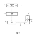
- FIG. 2 shows a headlamp unit whose lighting conditions are controlled by a navigation device 6.
- the support frame 3 shown in a side view of one of FIG. 1 illustrated light modules is connected via the drive 5 with an actuator 7.
- an actuator an electric motor, hydraulics or pneumatics are suitable.
- the actuator 7 is controlled by a mounted on the headlamp unit, equipped with a microprocessor electronic control unit 8, which in turn has a data connection to the navigation device 6.
- control unit 8 controls all other drives which are connected to the light modules or their support frame and swing frame, so that all light modules of the headlamp unit can be pivoted both vertically and horizontally.
- the navigation device 6 determines the position of the vehicle with respect to a digital road database.
- the navigation device 6 supplies the control unit 8 with data relating to the type of road being traveled and the current as well as the immediately following road.
- the control unit 8 receives information about whether the vehicle is now inside or outside a town, on a country lane or highway, on a straight line or a winding road, such as a hairpin bend. Will one Traverse curve, the curve radius of the control unit 8 is also used as a parameter for setting the light modules.
- 8 signals of a rain sensor for detecting wet or bad weather can be evaluated by the specially assigned control unit.
- the control unit 8 controls the actuator 7 and thereby sets different lighting conditions or lighting modes. It is adjusted by adjusting the vehicle interior light module dynamic cornering light, parking light, bad weather light and sign lighting. The alignment of the vehicle exterior light module sets dynamic cornering light, low beam, high beam, high street light, highway light and high speed motorway light. During the adjustment of one of the two or both light modules both light modules remain in operation.
- the invention is not limited to the specific structure shown in the preceding figures and the described operation of the headlamp unit. Rather, it may be modified in any manner without departing from the basic principle of the invention.
- the headlamp unit may comprise more than two light modules.
- the setting of the illumination states can also be achieved by simultaneous pivoting of a plurality of headlamp unit, So be accomplished in the above example of both light modules.
- the support frame of a headlamp unit can be integrally formed. Then the light modules arranged therein can only be pivoted together about the horizontal axis.
- the invention is not limited exclusively to motor vehicles, although it is particularly advantageous there and in particular in passenger vehicles.
- the invention is more suitable for arbitrarily designed motor vehicles.
Landscapes
- Engineering & Computer Science (AREA)
- Mechanical Engineering (AREA)
- Lighting Device Outwards From Vehicle And Optical Signal (AREA)
Description
- Die Erfindung betrifft eine Scheinwerfereinheit für ein Fahrzeug und ein Verfahren zum adaptiven Ausleuchten einer Fahrstrecke.
- Aus der
Europäischen Patentanmeldung EP 0 679 551 A2 ist eine Lichteinheit für Kraftfahrzeuge mit zwei Scheinwerfern und einer zusätzlichen Leuchte bekannt. Die Reflektoren der Scheinwerfer und der Leuchte sind in einem Rahmen angeordnet. Mittels einer Verstelleinrichtung sind die Reflektoren der Scheinwerfer um eine horizontale und eine vertikale Achse verschwenkbar. - Die
Deutsche Offenlegungsschrift DE 101 20 217 A1 beschreibt einen Scheinwerfer für Kraftfahrzeuge mit einem Lichtmodul, das zur Erzeugung von Kurvenlicht um eine Achse schwenkbar gelagert ist. - Die
Deutsche Offenlegungsschrift DE 198 02 023 A1 beschreibt ein Beleuchtungssystem mit Scheinwerfern für ein Abblendlicht und ein verstellbares Kurvenlicht. - Die
DE 102 11 816 A1 offenbart einen Fahrzeugscheinwerfer mit mindestens zwei Lichteinheiten, die mittels einer Verstelleinrichtung um eine horizontale und eine vertikale Schwenkachse verschwenkbar angeordnet sind. Die Verstelleinrichtung umfasst ein Vertikaleinstellelement zur Verstellung eines Vertikallagerpunktes um die horizontale Schwenkachse und ein Horizontaleinstellelement zur Verstellung eines horizontal versetzt zum Vertikallagerpunkt angeordneten Horizontallagerpunktes in die vertikale Schwenkachse. - Der vorliegenden Erfindung liegt nun die Aufgabe zugrunde, eine Scheinwerfereinheit und ein Verfahren zum adaptiven Ausleuchten einer Fahrstrecke bereitzustellen, die beim Umschalten zwischen unterschiedlichen Beleuchtungszuständen abrupte Sichtverluste vermeiden.
- Erfindungsgemäß wird diese Aufgabe durch eine Scheinwerfereinheit und ein Verfahren gelöst, wie sie in den unabhängigen Patentansprüchen definiert sind.
- Demgemäß ist vorgesehen, dass eine Scheinwerfereinheit für ein Fahrzeug wenigstens zwei relativ zueinander verschwenkbare Lichtmodule aufweist. Wenigstens ein Schwenkmodul nimmt eines der Lichtmodule auf und ist um eine Achse schwenkbar gelagert. Wenigstens ein Tragrahmen ist mit dem Schwenkmodul verbunden.
- Beim erfindungsgemäßen Verfahren zum adaptiven Ausleuchten einer Fahrstrecke werden beim gleichzeitigen Betrieb wenigstens zweier Lichtmodule durch Verschwenken wenigstens eines der Lichtmodule wenigstens zwei Beleuchtungszustände eingestellt. Als einstellbare Beleuchtungszustände kommen dynamisches Kurvenlicht, dynamisches Abbiegelicht, Abblendlicht, Fernlicht, Standlicht, Landstraßenlicht, Schlechtwetterlicht wie beispielsweise aus der
Offenlegungsschrift DE 101 44 846 A1 bekannt, Schilderberleuchtung, Autobahnlicht und Autobahnlicht für Hochgeschwindigkeit in Frage. - Die vorliegende Erfindung gestattet durch die Nutzung zweier Lichtmodule, die relativ zueinander verschwenkbar sind, eine kontinuierliche Ausleuchtung des Sichtfelds eines Fahrzeugführers auch während des Umschaltens zwischen unterschiedlichen Beleuchtungszuständen.
- Vorteilhafte Ausgestaltungen und Weiterbildungen der Erfindung sind Gegenstand der Unteransprüche sowie der Beschreibung unter Bezugnahme auf die Zeichnung.
- Die Tragrahmen sind um eine Achse schwenkbar gelagert, die im Wesentlichen senkrecht zur ersten Achse. Die erste Achse verläuft hier ebenfalls sehr vorteilhaft im Wesentlichen vertikal und die zweite Achse im Wesentlichen horizontal. Das Schwenkmodul ist dabei im Tragrahmen schwenkbar gelagert.
- Die beiden Lichtmodule sind jeweils in separaten Schwenkmodulen angeordnet. Zusätzlich oder alternativ kann auch vorgesehen sein, dass wenigstens zwei Lichtmodule in zwei separaten Tragrahmen angeordnet sind.
- In einer vorteilhaften Ausgestaltung sind die Tragrahmen miteinander gekoppelt.
- In einer vorteilhaften Ausgestaltung weisen das Schwenkmodul und/oder der Tragrahmen eine Schwenkkupplung auf. Besonders vorteilhaft ist es in diesem Zusammenhang, wenn die Schwenkkupplung des Schwenkmoduls und/oder des Tragrahmens mit einem Antrieb gekoppelt ist, der von einem Navigationsgerät gesteuert ist.
- In einer vorteilhaften Ausgestaltung des erfindungsgemäßen Verfahrens stellt das fahrzeuginnere Lichtmodul wenigstens einen der nachfolgenden Beleuchtungszustände ein: Dynamisches Abbiegelicht, Standlicht, Schlechtwetterlicht, Schilderbeleuchtung.
- In einer zusätzlichen oder alternativen, ebenfalls vorteilhaften Ausgestaltung des erfindungsgemäßen Verfahrens stellt das fahrzeugäußere Lichtmodul wenigstens einen der nachfolgenden Beleuchtungszustände ein: Dynamisches Kurvenlicht, Abblendlicht, Fernlicht, Landstraßenlicht, Autobahnlicht, Autobahnlicht für Hochgeschwindigkeit.
- Vorteilhafterweise wird durch das erfindungsgemäße Verfahren die Position des Fahrzeugs ermittelt und wenigstens einer der Beleuchtungszustände aufgrund von Daten einer digitalen Straßendatenbank eingestellt.
- Die Erfindung wird nachfolgend anhand der in den Figuren der Zeichnung angegebenen Ausführungsbeispiele näher erläutert. Es zeigt dabei:
- Fig. 1
- eine perspektivische Ansicht einer Scheinwerfereinheit;
- Figur 2
- eine über ein Navigationsgerät gesteuerte Scheinwerfereinheit.
- In allen Figuren der Zeichnung sind gleiche bzw. funktionsgleiche Elemente - sofern nichts anderes angegeben ist - mit gleichen Bezugszeichen versehen worden.
-
Figur 1 veranschaulicht eine erfindungsgemäße Scheinwerfereinheit mit zwei Lichtmodulen 1. Die Lichtmodule 1 sind Projektionsmodule, die jeweils aus einem Reflektor, einer Linse und einer dazwischenliegenden Blende bestehen. - Die Lichtmodule 1 sind in zwei separaten Schwenkmodulen 2 befestigt. Die Schwenkmodule 2 sind jeweils in einen separaten Tragrahmen 3 eingesetzt. Die Tragrahmen 3 weisen oberhalb und unterhalb der Lichtmodule vorspringende Nasen 31 mit Öffnungen auf, in die von den Schwenkmodulen 2 nach unten abragende Zapfen eingreifen. Durch diese Lagerung wird eine im Wesentlichen vertikale Achse (a) definiert, um die das Schwenkmodul 2 und damit das Lichtmodul 1 gegenüber dem Tragrahmen 3 in einer im Wesentlichen horizontalen Richtung geschwenkt werden kann.
- Der untere Zapfen des Schwenkmoduls 2 bildet eine Schwenkkupplung 4 aus, an die ein nicht dargestellter motorischer Antrieb gekoppelt ist. Dieser Antrieb verschwenkt das Schwenkmodul um die horizontale Achse (a).
- Die Tragrahmen 3 weisen jeweils beidseitig Vorsprünge 32 auf, die eine im Wesentlichen horizontale Achse (b) definieren, um die die Tragrahmen geschwenkt werden können. Die Achse (b) liegt etwa auf halber Höhe des Lichtmoduls 1, um eine möglichst geringe Bauhöhe zu ermöglichen. Die Schwenkachsen (a) und (b) verlaufen im Wesentlichen senkrecht zueinander. An den voneinander abgewandten Seiten der Tragrahmen 3 bilden die Vorsprünge 32 jeweils Schwenkkupplungen aus, in die jeweils ein Antrieb 5 eingreift. Der Antrieb 5 ist ein von einem Aktuator betätigter Hebel.
- An ihren einander zugewandten Seiten sind die Tragrahmen 3 über einen Ring 33 gekoppelt, in den die einander zugewandten Vorsprünge beider Tragrahmen 3 eingreifen. Die Tragrahmen 3 können einzeln und in unterschiedlicher Weise über Antriebe um die Achse (b) geschwenkt werden.
- Der Ring 33 kann auf einer beweglichen Schiene angeordnet werden, um eine Höheneinstellung der Tragrahmen 3 und somit der Lichtmodule 1 zu ermöglichen. Bei einer zweiteiligen Ausgestaltung des Rings 33 können beide Lichtmodule getrennt voneinander vertikal eingestellt werden. Die Achse (b) kann dann in ihrer Neigung verändert werden.
-
Figur 2 zeigt eine Scheinwerfereinheit, deren Beleuchtungszustände über ein Navigationsgerät 6 gesteuert werden. Der in einer Seitenansicht dargestellte Tragrahmen 3 eines der inFigur 1 dargestellten Lichtmodule ist über den Antrieb 5 mit einem Aktuator 7 verbunden. Als Aktuator eignen sich ein Elektromotor, eine Hydraulik oder eine Pneumatik. Der Aktuator 7 wird von einer an der Scheinwerfereinheit befestigten, mit einem Mikroprozessor ausgerüsteten elektronischen Steuereinheit 8 gesteuert, die wiederum eine Datenverbindung zum Navigationsgerät 6 aufweist. - In analoger Weise steuert die Steuereinheit 8 alle weiteren Antriebe, die mit den Lichtmodulen bzw. deren Tragrahmen und Schwenkrahmen verbunden sind, so dass alle Lichtmodule der Scheinwerfereinheit sowohl vertikal als auch horizontal verschwenkt werden können.
- Das Navigationsgerät 6 ermittelt die Position des Fahrzeugs in Bezug auf eine digitale Straßendatenbank. Das Navigationsgerät 6 führt der Steuereinheit 8 Daten zu, die den Typ der gerade befahrenen Straße und den momentanen sowie den unmittelbar folgenden Straßenverlauf betreffen. Damit erhält die Steuereinheit 8 Informationen darüber, ob sich das Fahrzeug nun innerhalb oder außerhalb eines Orts, auf einer Landstraße oder einer Autobahn, auf einer geraden Strecke oder einer kurvigen Strecke, beispielsweise eine Serpentine, befindet. Wird eine Kurve durchfahren, wird der Kurvenradius vom Steuergerät 8 ebenfalls als Parameter zur Einstellung der Lichtmodule verwendet. Ferner können von der eigens dazu ausgelgten Steuereinheit 8 Signale eines Regensensors zur Erkennung von Nässe beziehungsweise Schlechtwetter ausgewertet werden.
- Ausgehend von zumindest einigen dieser Daten steuert die Steuereinheit 8 den Aktuator 7 und stellt dadurch unterschiedliche Beleuchtungszustände bzw. Beleuchtungsmodi ein. Dabei wird durch Verstellen des fahrzeuginneren Lichtmoduls dynamisches Abbiegelicht, Standlicht, Schlechtwetterlicht und Schilderbeleuchtung eingestellt. Mit der Ausrichtung des fahrzeugäußeren Lichtmoduls wird dynamisches Kurvenlicht, Abblendlicht, Fernlicht, Landstraßenlicht, Autobahnlicht und Autobahnlicht für Hochgeschwindigkeit eingestellt. Während des Verstellens eines der beiden oder beider Lichtmodule bleiben beide Lichtmodule in Betrieb.
- Obgleich die vorliegende Erfindung vorstehend anhand eines bevorzugten Ausführungsbeispiels beschrieben wurde, ist sie nicht darauf beschränkt, sondern auf vielfältige Art und Weise modifizierbar.
- So sei die Erfindung nicht auf den in den vorstehenden Figuren dargestellten, speziellen Aufbau und die beschriebene Funktionsweise der Scheinwerfereinheit beschränkt. Vielmehr kann diese auf beliebige Art und Weise modifiziert werden, ohne dass vom grundlegenden Prinzip der Erfindung abgewichen wird. Insbesondere kann die Scheinwerfereinheit mehr als zwei Lichtmodule umfassen.
- Ferner kann die Einstellung der Beleuchtungszustände auch durch gleichzeitiges Verschwenken mehrerer Scheinwerfereinheit, also in obigem Beispiel beider Lichtmodule bewerkstelligt werden.
- Darüber hinaus können die Tragrahmen einer Scheinwerfereinheit einstückig ausgebildet werden. Dann lassen sich die darin angeordneten Lichtmodule nur gemeinsam um die horizontale Achse schwenken.
- Auch sei die Erfindung nicht ausschließlich auf Kraftfahrzeuge beschränkt, wenngleich sie dort und insbesondere bei Personenkraftfahrzeugen besonders vorteilhaft ist. Die Erfindung eignet sich vielmehr bei beliebig ausgestalteten Kraftfahrzeugen.
-
- 1
- Lichtmodul
- 2
- Schwenkmodul
- 3
- Tragrahmen
- 31
- Nase
- 32
- Vorsprung
- 33
- Ring
- 4
- Schwenkkupplung
- 5
- Antrieb
- 6
- Navigationsgerät
- 7
- Aktuator
- 8
- Steuereinheit
Claims (9)
- Scheinwerfereinheit für ein Fahrzeug, aufweisend wenigstens zwei Lichtmodule (1) und wenigstens zwei Schwenkmodule (2), die jeweils eines der Lichtmodule (1) aufnehmen
gekennzeichnet durch
wenigstens zwei Tragrahmen (3), an denen jeweils eines der Schwenkmodule (2) bezüglich einer ersten Achse schwenkbar gelagert ist, wobei die Tragrahmen (3) jeweils unabhängig voneinander bezüglich einer im Wesentlichen senkrecht zur ersten Achse verlaufenden zweiten Achse gelagert sind. - Scheinwerfereinheit nach Anspruch 1, dadurch gekennzeichnet, dass die erste Achse im Wesentlichen vertikal verläuft und die zweite Achse im Wesentlichen horizontal verläuft.
- Scheinwerfereinheit nach Anspruch 1 oder 2, dadurch gekennzeichnet, dass die Tragrahmen (3) miteinander gekoppelt sind.
- Scheinwerfereinheit nach Anspruch 3, dadurch gekennzeichnet, dass das Schwenkmodul (2) und/oder der Tragrahmen eine Schwenkkupplung (4) aufweist.
- Scheinwerfereinheit nach Anspruch 4, dadurch gekennzeichnet, dass die Schwenkkupplung des Schwenkmoduls (2) und/oder des Tragrahmens (3) mit einem Antrieb (5) gekoppelt ist, der von einem Navigationsgerät (6) gesteuert ist.
- Verfahren zum adaptiven Ausleuchten einer Fahrstrecke, bei dem beim gleichzeitigen Betrieb wenigstens zweier Lichtmodule (2) einer Scheinwerfereinheit nach einem der Ansprüche 1 bis 5 durch Verschwenken wenigstens eines der Lichtmodule (2) wenigstens zwei der nachfolgenden Beleuchtungszustände eingestellt werden:- dynamisches Kurvenlicht,- dynamisches Abbiegelicht,- Abblendlicht,- Fernlicht,- Standlicht,- Landstraßenlicht,- Schlechtwetterlicht,- Schilderbeleuchtung,- Autobahnlicht,- Autobahnlicht für Hochgeschwindigkeit.
- Verfahren nach dem vorhergehenden Anspruch, dadurch gekennzeichnet, dass das fahrzeuginnere Lichtmodul (2) wenigstens einen der nachfolgenden Beleuchtungszustände einstellt:- Dynamisches Abbiegelicht,- Standlicht,- Schlechtwetterlicht,- Schilderbeleuchtung.
- Verfahren nach einem der vorhergehenden Verfahrensansprüche, dadurch gekennzeichnet, dass das fahrzeugäußere Lichtmodul wenigstens einen der nachfolgenden Beleuchtungszustände einstellt:- Dynamisches Kurvenlicht,- Abblendlicht,- Fernlicht,- Landstraßenlicht,- Autobahnlicht,- Autobahnlicht für Hochgeschwindigkeit.
- Verfahren nach einem der vorhergehenden Verfahrensansprüche, dadurch gekennzeichnet, dass die Position des Fahrzeugs ermittelt wird und wenigstens einer der Beleuchtungszustände aufgrund von Daten einer digitalen Straßendatenbank eingestellt wird.
Applications Claiming Priority (2)
| Application Number | Priority Date | Filing Date | Title |
|---|---|---|---|
| DE102004022893 | 2004-05-10 | ||
| DE102004022893A DE102004022893A1 (de) | 2004-05-10 | 2004-05-10 | Scheinwerfereinheit für ein Fahrzeug und Verfahren zum adaptiven Ausleuchten einer Fahrstrecke |
Publications (3)
| Publication Number | Publication Date |
|---|---|
| EP1595740A2 EP1595740A2 (de) | 2005-11-16 |
| EP1595740A3 EP1595740A3 (de) | 2006-11-22 |
| EP1595740B1 true EP1595740B1 (de) | 2009-09-30 |
Family
ID=34936228
Family Applications (1)
| Application Number | Title | Priority Date | Filing Date |
|---|---|---|---|
| EP05009927A Expired - Lifetime EP1595740B1 (de) | 2004-05-10 | 2005-05-06 | Scheinwerfereinheit für ein Fahrzeug und Verfahren zum adaptiven Ausleuchten einer Fahrstrecke |
Country Status (3)
| Country | Link |
|---|---|
| EP (1) | EP1595740B1 (de) |
| AT (1) | ATE444203T1 (de) |
| DE (2) | DE102004022893A1 (de) |
Cited By (1)
| Publication number | Priority date | Publication date | Assignee | Title |
|---|---|---|---|---|
| FR3116103A1 (fr) * | 2020-11-06 | 2022-05-13 | Psa Automobiles Sa | Dispositif d’éclairage adaptatif comportant un module tournant, et véhicule ainsi équipé. |
Families Citing this family (4)
| Publication number | Priority date | Publication date | Assignee | Title |
|---|---|---|---|---|
| FR2902380B1 (fr) * | 2006-06-19 | 2008-09-05 | Valeo Vision Sa | Ensemble projecteur a trois fonctions pour vehicule automobile |
| DE102006058212A1 (de) * | 2006-12-11 | 2008-06-12 | Bayerische Motoren Werke Ag | Kraftfahrzeugscheinwerfersystem |
| DE102010039399A1 (de) | 2010-08-17 | 2012-02-23 | Visteon Global Technologies, Inc. | Prädiktiv-adaptive Frontbeleuchtung eines Kraftfahrzeuges |
| DE102016117552B4 (de) * | 2016-09-19 | 2025-10-02 | HELLA GmbH & Co. KGaA | Drehlager zur drehbaren Aufnahme eines Lichtmoduls in einem Tragrahmen eines Scheinwerfers |
Family Cites Families (13)
| Publication number | Priority date | Publication date | Assignee | Title |
|---|---|---|---|---|
| JPH0782761B2 (ja) * | 1990-09-26 | 1995-09-06 | 株式会社小糸製作所 | クリアランスランプ一体型自動車用ヘッドランプ |
| JP2579256Y2 (ja) * | 1992-04-30 | 1998-08-20 | 株式会社小糸製作所 | 光束パターン可変型4灯式前照灯 |
| DE4425584C1 (de) * | 1994-07-20 | 1996-02-08 | Hansa Metallwerke Ag | Sanitäres Thermostatventil |
| JP3267931B2 (ja) * | 1998-05-14 | 2002-03-25 | 宋 炳 俊 | 折曲機用角度測定装置 |
| DE19914412A1 (de) * | 1999-03-30 | 2000-12-28 | Bosch Gmbh Robert | Scheinwerfer für Fahrzeuge zur Aussendung eines veränderlichen Lichtbündels und Scheinwerferanlage mit wenigstens zwei der Scheinwerfer |
| DE19933663B4 (de) * | 1999-07-17 | 2012-05-03 | Automotive Lighting Reutlingen Gmbh | Scheinwerfer für Fahrzeuge |
| JP3964101B2 (ja) * | 2000-05-24 | 2007-08-22 | 株式会社小糸製作所 | 車両用前照灯 |
| DE10120217A1 (de) * | 2001-04-25 | 2002-10-31 | Hella Kg Hueck & Co | Scheinwerfer für Fahrzeuge |
| DE10144846B4 (de) * | 2001-09-12 | 2015-03-26 | Volkswagen Ag | Scheinwerfereinheit für Fahrzeuge mit Kurvenlichtfunktion und Verfahren zum Steuern einer solchen Scheinwerfereinheit |
| DE10209623A1 (de) * | 2002-03-05 | 2003-09-25 | Automotive Lighting Reutlingen | Scheinwerfer, insbesondere für ein Kraftfahrzeug |
| DE10211816B4 (de) * | 2002-03-16 | 2014-05-28 | Hella Kgaa Hueck & Co. | Fahrzeugscheinwerfer |
| DE10217194B4 (de) * | 2002-04-18 | 2008-10-16 | Automotive Lighting Reutlingen Gmbh | Scheinwerfer |
| DE10228947B4 (de) * | 2002-06-28 | 2006-06-14 | Hella Kgaa Hueck & Co. | Scheinwerfer für Kraftfahrzeuge |
-
2004
- 2004-05-10 DE DE102004022893A patent/DE102004022893A1/de not_active Withdrawn
-
2005
- 2005-05-06 AT AT05009927T patent/ATE444203T1/de not_active IP Right Cessation
- 2005-05-06 DE DE502005008220T patent/DE502005008220D1/de not_active Expired - Lifetime
- 2005-05-06 EP EP05009927A patent/EP1595740B1/de not_active Expired - Lifetime
Cited By (1)
| Publication number | Priority date | Publication date | Assignee | Title |
|---|---|---|---|---|
| FR3116103A1 (fr) * | 2020-11-06 | 2022-05-13 | Psa Automobiles Sa | Dispositif d’éclairage adaptatif comportant un module tournant, et véhicule ainsi équipé. |
Also Published As
| Publication number | Publication date |
|---|---|
| EP1595740A2 (de) | 2005-11-16 |
| DE502005008220D1 (de) | 2009-11-12 |
| EP1595740A3 (de) | 2006-11-22 |
| ATE444203T1 (de) | 2009-10-15 |
| DE102004022893A1 (de) | 2005-12-08 |
Similar Documents
| Publication | Publication Date | Title |
|---|---|---|
| EP0780823B1 (de) | Beleuchtungsvorrichtung für Fahrzeuge | |
| DE19923187C2 (de) | Beleuchtungssystem für ein Kraftfahrzeug | |
| DE19530008A1 (de) | Beleuchtungseinrichtung für Fahrzeuge | |
| DE102013016761A1 (de) | Verfahren zum Betrieb von Scheinwerfern eines Kraftfahrzeugs, Scheinwerfersystem sowie Kraftfahrzeug | |
| DE10054524B4 (de) | Automatisches Niveauausgleichsgerät für Kraftfahrzeugscheinwerfer | |
| DE19907943C2 (de) | Kraftfahrzeugscheinwerfer mit einer Umlenkvorrichtung zum Ändern der Richtung zumindest eines Teils eines Lichtbündels | |
| EP1353823A1 (de) | Scheinwerfereinheit für einspurige zweiradfahrzeuge | |
| EP1070637B1 (de) | Rückspiegel mit schwenkbar gelagerten Teilspiegeln | |
| EP1093965A2 (de) | Vorrichtung zur Steuerung der Lichtverteilung einer Scheinwerferanordnung eines Fahrzeuges | |
| EP0780624B1 (de) | Abblendlicht-Scheinwerfer für Fahrzeuge | |
| WO1999048721A1 (de) | Scheinwerferanlage für fahrzeuge zur aussendung veränderlicher lichtbündel | |
| EP1889746A1 (de) | Beleuchtungssystem für Fahrzeuge | |
| DE102009022637B4 (de) | Verfahren und Vorrichtung zur Ansteuerung der Beleuchtungseinrichtung eines Kraftfahrzeugs | |
| DE102004022893A1 (de) | Scheinwerfereinheit für ein Fahrzeug und Verfahren zum adaptiven Ausleuchten einer Fahrstrecke | |
| DE10151514A1 (de) | Einstellverfahren für Scheinwerfer | |
| DE19914412A1 (de) | Scheinwerfer für Fahrzeuge zur Aussendung eines veränderlichen Lichtbündels und Scheinwerferanlage mit wenigstens zwei der Scheinwerfer | |
| DE102007013810A1 (de) | Verstellbare Arbeitsleuchten für lanswirtschaftliche Arbeitsmaschinen | |
| DE10342592B4 (de) | Verfahren zum Steuern eines Fahrzeugscheinwerfers und Steuervorrichtung für einen Fahrzeugscheinwerfer | |
| DE10242865A1 (de) | Scheinwerfer für ein Kraftfahrzeug | |
| DE10310232A1 (de) | Kraftfahrzeug mit mindestens einem für eine Verkehrsart ausgelegten Scheinwerfer | |
| EP1666304A2 (de) | Scheinwerfer für Fahrzeuge | |
| DE102020130540A1 (de) | Projektionsmodul, Scheinwerfer, Kraftfahrzeug | |
| DE102006036358A1 (de) | Scheinwerfer in einem Kraftfahrzeug | |
| DE102025125688B3 (de) | Leuchtsystem für einen Kraftwagen sowie Verfahren | |
| DE10045943A1 (de) | Vorrichtung zum Verstellen einer Scheinwerfereinheit |
Legal Events
| Date | Code | Title | Description |
|---|---|---|---|
| PUAI | Public reference made under article 153(3) epc to a published international application that has entered the european phase |
Free format text: ORIGINAL CODE: 0009012 |
|
| AK | Designated contracting states |
Kind code of ref document: A2 Designated state(s): AT BE BG CH CY CZ DE DK EE ES FI FR GB GR HU IE IS IT LI LT LU MC NL PL PT RO SE SI SK TR |
|
| AX | Request for extension of the european patent |
Extension state: AL BA HR LV MK YU |
|
| RIN1 | Information on inventor provided before grant (corrected) |
Inventor name: SCHNEIDER, INGOLF Inventor name: KISTINGER, THOMAS Inventor name: REICHMANN, KARL-HEIZ Inventor name: FEID, THOMAS Inventor name: KATHMANN, JOERG Inventor name: GOTTWALD, WOLFGANG |
|
| PUAL | Search report despatched |
Free format text: ORIGINAL CODE: 0009013 |
|
| AK | Designated contracting states |
Kind code of ref document: A3 Designated state(s): AT BE BG CH CY CZ DE DK EE ES FI FR GB GR HU IE IS IT LI LT LU MC NL PL PT RO SE SI SK TR |
|
| AX | Request for extension of the european patent |
Extension state: AL BA HR LV MK YU |
|
| RIC1 | Information provided on ipc code assigned before grant |
Ipc: B60Q 1/00 20060101ALI20061013BHEP Ipc: B60Q 1/06 20060101ALI20061013BHEP Ipc: B60Q 1/12 20060101AFI20050922BHEP |
|
| 17P | Request for examination filed |
Effective date: 20070312 |
|
| 17Q | First examination report despatched |
Effective date: 20070423 |
|
| AKX | Designation fees paid |
Designated state(s): AT BE BG CH CY CZ DE DK EE ES FI FR GB GR HU IE IS IT LI LT LU MC NL PL PT RO SE SI SK TR |
|
| GRAP | Despatch of communication of intention to grant a patent |
Free format text: ORIGINAL CODE: EPIDOSNIGR1 |
|
| RIN1 | Information on inventor provided before grant (corrected) |
Inventor name: SCHNEIDER, INGOLF Inventor name: REICHMANN, KARL-HEIZ Inventor name: KISTINGER, THOMAS Inventor name: KATHMANN, JOERG Inventor name: GOTTWALD, WOLFGANG Inventor name: FEID, THOMAS |
|
| GRAS | Grant fee paid |
Free format text: ORIGINAL CODE: EPIDOSNIGR3 |
|
| GRAA | (expected) grant |
Free format text: ORIGINAL CODE: 0009210 |
|
| AK | Designated contracting states |
Kind code of ref document: B1 Designated state(s): AT BE BG CH CY CZ DE DK EE ES FI FR GB GR HU IE IS IT LI LT LU MC NL PL PT RO SE SI SK TR |
|
| REG | Reference to a national code |
Ref country code: CH Ref legal event code: EP Ref country code: GB Ref legal event code: FG4D Free format text: NOT ENGLISH |
|
| REG | Reference to a national code |
Ref country code: IE Ref legal event code: FG4D |
|
| REF | Corresponds to: |
Ref document number: 502005008220 Country of ref document: DE Date of ref document: 20091112 Kind code of ref document: P |
|
| REG | Reference to a national code |
Ref country code: GB Ref legal event code: 732E Free format text: REGISTERED BETWEEN 20091105 AND 20091111 |
|
| PG25 | Lapsed in a contracting state [announced via postgrant information from national office to epo] |
Ref country code: SE Free format text: LAPSE BECAUSE OF FAILURE TO SUBMIT A TRANSLATION OF THE DESCRIPTION OR TO PAY THE FEE WITHIN THE PRESCRIBED TIME-LIMIT Effective date: 20090930 Ref country code: LT Free format text: LAPSE BECAUSE OF FAILURE TO SUBMIT A TRANSLATION OF THE DESCRIPTION OR TO PAY THE FEE WITHIN THE PRESCRIBED TIME-LIMIT Effective date: 20090930 Ref country code: FI Free format text: LAPSE BECAUSE OF FAILURE TO SUBMIT A TRANSLATION OF THE DESCRIPTION OR TO PAY THE FEE WITHIN THE PRESCRIBED TIME-LIMIT Effective date: 20090930 |
|
| LTIE | Lt: invalidation of european patent or patent extension |
Effective date: 20090930 |
|
| PG25 | Lapsed in a contracting state [announced via postgrant information from national office to epo] |
Ref country code: SI Free format text: LAPSE BECAUSE OF FAILURE TO SUBMIT A TRANSLATION OF THE DESCRIPTION OR TO PAY THE FEE WITHIN THE PRESCRIBED TIME-LIMIT Effective date: 20090930 Ref country code: PL Free format text: LAPSE BECAUSE OF FAILURE TO SUBMIT A TRANSLATION OF THE DESCRIPTION OR TO PAY THE FEE WITHIN THE PRESCRIBED TIME-LIMIT Effective date: 20090930 |
|
| NLV1 | Nl: lapsed or annulled due to failure to fulfill the requirements of art. 29p and 29m of the patents act | ||
| PG25 | Lapsed in a contracting state [announced via postgrant information from national office to epo] |
Ref country code: CZ Free format text: LAPSE BECAUSE OF FAILURE TO SUBMIT A TRANSLATION OF THE DESCRIPTION OR TO PAY THE FEE WITHIN THE PRESCRIBED TIME-LIMIT Effective date: 20090930 Ref country code: PT Free format text: LAPSE BECAUSE OF FAILURE TO SUBMIT A TRANSLATION OF THE DESCRIPTION OR TO PAY THE FEE WITHIN THE PRESCRIBED TIME-LIMIT Effective date: 20100201 Ref country code: EE Free format text: LAPSE BECAUSE OF FAILURE TO SUBMIT A TRANSLATION OF THE DESCRIPTION OR TO PAY THE FEE WITHIN THE PRESCRIBED TIME-LIMIT Effective date: 20090930 Ref country code: RO Free format text: LAPSE BECAUSE OF FAILURE TO SUBMIT A TRANSLATION OF THE DESCRIPTION OR TO PAY THE FEE WITHIN THE PRESCRIBED TIME-LIMIT Effective date: 20090930 Ref country code: ES Free format text: LAPSE BECAUSE OF FAILURE TO SUBMIT A TRANSLATION OF THE DESCRIPTION OR TO PAY THE FEE WITHIN THE PRESCRIBED TIME-LIMIT Effective date: 20100110 Ref country code: IS Free format text: LAPSE BECAUSE OF FAILURE TO SUBMIT A TRANSLATION OF THE DESCRIPTION OR TO PAY THE FEE WITHIN THE PRESCRIBED TIME-LIMIT Effective date: 20100130 |
|
| REG | Reference to a national code |
Ref country code: IE Ref legal event code: FD4D |
|
| PG25 | Lapsed in a contracting state [announced via postgrant information from national office to epo] |
Ref country code: SK Free format text: LAPSE BECAUSE OF FAILURE TO SUBMIT A TRANSLATION OF THE DESCRIPTION OR TO PAY THE FEE WITHIN THE PRESCRIBED TIME-LIMIT Effective date: 20090930 Ref country code: CY Free format text: LAPSE BECAUSE OF FAILURE TO SUBMIT A TRANSLATION OF THE DESCRIPTION OR TO PAY THE FEE WITHIN THE PRESCRIBED TIME-LIMIT Effective date: 20090930 |
|
| PG25 | Lapsed in a contracting state [announced via postgrant information from national office to epo] |
Ref country code: DK Free format text: LAPSE BECAUSE OF FAILURE TO SUBMIT A TRANSLATION OF THE DESCRIPTION OR TO PAY THE FEE WITHIN THE PRESCRIBED TIME-LIMIT Effective date: 20090930 Ref country code: IE Free format text: LAPSE BECAUSE OF FAILURE TO SUBMIT A TRANSLATION OF THE DESCRIPTION OR TO PAY THE FEE WITHIN THE PRESCRIBED TIME-LIMIT Effective date: 20090930 Ref country code: NL Free format text: LAPSE BECAUSE OF FAILURE TO SUBMIT A TRANSLATION OF THE DESCRIPTION OR TO PAY THE FEE WITHIN THE PRESCRIBED TIME-LIMIT Effective date: 20090930 |
|
| PLBE | No opposition filed within time limit |
Free format text: ORIGINAL CODE: 0009261 |
|
| STAA | Information on the status of an ep patent application or granted ep patent |
Free format text: STATUS: NO OPPOSITION FILED WITHIN TIME LIMIT |
|
| 26N | No opposition filed |
Effective date: 20100701 |
|
| PG25 | Lapsed in a contracting state [announced via postgrant information from national office to epo] |
Ref country code: GR Free format text: LAPSE BECAUSE OF FAILURE TO SUBMIT A TRANSLATION OF THE DESCRIPTION OR TO PAY THE FEE WITHIN THE PRESCRIBED TIME-LIMIT Effective date: 20091231 |
|
| BERE | Be: lapsed |
Owner name: GM GLOBAL TECHNOLOGY OPERATIONS, INC. Effective date: 20100531 |
|
| PG25 | Lapsed in a contracting state [announced via postgrant information from national office to epo] |
Ref country code: MC Free format text: LAPSE BECAUSE OF NON-PAYMENT OF DUE FEES Effective date: 20100531 |
|
| REG | Reference to a national code |
Ref country code: CH Ref legal event code: PL |
|
| PG25 | Lapsed in a contracting state [announced via postgrant information from national office to epo] |
Ref country code: CH Free format text: LAPSE BECAUSE OF NON-PAYMENT OF DUE FEES Effective date: 20100531 Ref country code: LI Free format text: LAPSE BECAUSE OF NON-PAYMENT OF DUE FEES Effective date: 20100531 |
|
| PG25 | Lapsed in a contracting state [announced via postgrant information from national office to epo] |
Ref country code: IT Free format text: LAPSE BECAUSE OF FAILURE TO SUBMIT A TRANSLATION OF THE DESCRIPTION OR TO PAY THE FEE WITHIN THE PRESCRIBED TIME-LIMIT Effective date: 20090930 Ref country code: BE Free format text: LAPSE BECAUSE OF NON-PAYMENT OF DUE FEES Effective date: 20100531 |
|
| REG | Reference to a national code |
Ref country code: DE Ref legal event code: R081 Ref document number: 502005008220 Country of ref document: DE Owner name: GM GLOBAL TECHNOLOGY OPERATIONS LLC (N. D. GES, US Free format text: FORMER OWNER: GM GLOBAL TECHNOLOGY OPERATIONS, INC., DETROIT, MICH., US Effective date: 20110323 Ref country code: DE Ref legal event code: R081 Ref document number: 502005008220 Country of ref document: DE Owner name: GM GLOBAL TECHNOLOGY OPERATIONS LLC (N. D. GES, US Free format text: FORMER OWNER: GM GLOBAL TECHNOLOGY OPERATIONS, INC., DETROIT, US Effective date: 20110323 |
|
| PG25 | Lapsed in a contracting state [announced via postgrant information from national office to epo] |
Ref country code: AT Free format text: LAPSE BECAUSE OF NON-PAYMENT OF DUE FEES Effective date: 20100506 |
|
| PG25 | Lapsed in a contracting state [announced via postgrant information from national office to epo] |
Ref country code: BG Free format text: LAPSE BECAUSE OF FAILURE TO SUBMIT A TRANSLATION OF THE DESCRIPTION OR TO PAY THE FEE WITHIN THE PRESCRIBED TIME-LIMIT Effective date: 20090930 Ref country code: LU Free format text: LAPSE BECAUSE OF NON-PAYMENT OF DUE FEES Effective date: 20100506 Ref country code: HU Free format text: LAPSE BECAUSE OF FAILURE TO SUBMIT A TRANSLATION OF THE DESCRIPTION OR TO PAY THE FEE WITHIN THE PRESCRIBED TIME-LIMIT Effective date: 20100401 |
|
| PG25 | Lapsed in a contracting state [announced via postgrant information from national office to epo] |
Ref country code: TR Free format text: LAPSE BECAUSE OF FAILURE TO SUBMIT A TRANSLATION OF THE DESCRIPTION OR TO PAY THE FEE WITHIN THE PRESCRIBED TIME-LIMIT Effective date: 20090930 |
|
| REG | Reference to a national code |
Ref country code: FR Ref legal event code: PLFP Year of fee payment: 12 |
|
| REG | Reference to a national code |
Ref country code: FR Ref legal event code: PLFP Year of fee payment: 13 |
|
| PGFP | Annual fee paid to national office [announced via postgrant information from national office to epo] |
Ref country code: DE Payment date: 20170502 Year of fee payment: 13 Ref country code: FR Payment date: 20170413 Year of fee payment: 13 Ref country code: GB Payment date: 20170503 Year of fee payment: 13 |
|
| REG | Reference to a national code |
Ref country code: DE Ref legal event code: R119 Ref document number: 502005008220 Country of ref document: DE |
|
| GBPC | Gb: european patent ceased through non-payment of renewal fee |
Effective date: 20180506 |
|
| PG25 | Lapsed in a contracting state [announced via postgrant information from national office to epo] |
Ref country code: DE Free format text: LAPSE BECAUSE OF NON-PAYMENT OF DUE FEES Effective date: 20181201 Ref country code: FR Free format text: LAPSE BECAUSE OF NON-PAYMENT OF DUE FEES Effective date: 20180531 Ref country code: GB Free format text: LAPSE BECAUSE OF NON-PAYMENT OF DUE FEES Effective date: 20180506 |