EP1595754A1 - Assemblage d'un module de coussin gonflable sur un volant - Google Patents
Assemblage d'un module de coussin gonflable sur un volant Download PDFInfo
- Publication number
- EP1595754A1 EP1595754A1 EP04425334A EP04425334A EP1595754A1 EP 1595754 A1 EP1595754 A1 EP 1595754A1 EP 04425334 A EP04425334 A EP 04425334A EP 04425334 A EP04425334 A EP 04425334A EP 1595754 A1 EP1595754 A1 EP 1595754A1
- Authority
- EP
- European Patent Office
- Prior art keywords
- module
- steering wheel
- airbag module
- retaining assembly
- bracket
- Prior art date
- Legal status (The legal status is an assumption and is not a legal conclusion. Google has not performed a legal analysis and makes no representation as to the accuracy of the status listed.)
- Granted
Links
- 230000000284 resting effect Effects 0.000 claims abstract description 15
- 230000004913 activation Effects 0.000 claims abstract description 13
- 238000006073 displacement reaction Methods 0.000 claims description 10
- 230000008878 coupling Effects 0.000 claims description 8
- 238000010168 coupling process Methods 0.000 claims description 8
- 238000005859 coupling reaction Methods 0.000 claims description 8
- 230000000712 assembly Effects 0.000 description 9
- 238000000429 assembly Methods 0.000 description 9
- 230000003321 amplification Effects 0.000 description 3
- 238000003199 nucleic acid amplification method Methods 0.000 description 3
- 239000000463 material Substances 0.000 description 2
- 238000000465 moulding Methods 0.000 description 2
- 230000003213 activating effect Effects 0.000 description 1
- 230000004075 alteration Effects 0.000 description 1
- 238000005452 bending Methods 0.000 description 1
- 230000008901 benefit Effects 0.000 description 1
- 230000008859 change Effects 0.000 description 1
- 238000003780 insertion Methods 0.000 description 1
- 230000037431 insertion Effects 0.000 description 1
- 238000009434 installation Methods 0.000 description 1
- 239000002184 metal Substances 0.000 description 1
- 239000000088 plastic resin Substances 0.000 description 1
- 230000000717 retained effect Effects 0.000 description 1
- 238000000926 separation method Methods 0.000 description 1
Images


Classifications
-
- B—PERFORMING OPERATIONS; TRANSPORTING
- B60—VEHICLES IN GENERAL
- B60R—VEHICLES, VEHICLE FITTINGS, OR VEHICLE PARTS, NOT OTHERWISE PROVIDED FOR
- B60R21/00—Arrangements or fittings on vehicles for protecting or preventing injuries to occupants or pedestrians in case of accidents or other traffic risks
- B60R21/02—Occupant safety arrangements or fittings, e.g. crash pads
- B60R21/16—Inflatable occupant restraints or confinements designed to inflate upon impact or impending impact, e.g. air bags
- B60R21/20—Arrangements for storing inflatable members in their non-use or deflated condition; Arrangement or mounting of air bag modules or components
- B60R21/203—Arrangements for storing inflatable members in their non-use or deflated condition; Arrangement or mounting of air bag modules or components in steering wheels or steering columns
- B60R21/2035—Arrangements for storing inflatable members in their non-use or deflated condition; Arrangement or mounting of air bag modules or components in steering wheels or steering columns using modules containing inflator, bag and cover attachable to the steering wheel as a complete sub-unit
- B60R21/2037—Arrangements for storing inflatable members in their non-use or deflated condition; Arrangement or mounting of air bag modules or components in steering wheels or steering columns using modules containing inflator, bag and cover attachable to the steering wheel as a complete sub-unit the module or a major component thereof being yieldably mounted, e.g. for actuating the horn switch or for protecting the driver in a non-deployment situation
-
- B—PERFORMING OPERATIONS; TRANSPORTING
- B60—VEHICLES IN GENERAL
- B60R—VEHICLES, VEHICLE FITTINGS, OR VEHICLE PARTS, NOT OTHERWISE PROVIDED FOR
- B60R21/00—Arrangements or fittings on vehicles for protecting or preventing injuries to occupants or pedestrians in case of accidents or other traffic risks
- B60R21/02—Occupant safety arrangements or fittings, e.g. crash pads
- B60R21/16—Inflatable occupant restraints or confinements designed to inflate upon impact or impending impact, e.g. air bags
- B60R21/20—Arrangements for storing inflatable members in their non-use or deflated condition; Arrangement or mounting of air bag modules or components
- B60R21/201—Packaging straps or envelopes for inflatable members
-
- B—PERFORMING OPERATIONS; TRANSPORTING
- B62—LAND VEHICLES FOR TRAVELLING OTHERWISE THAN ON RAILS
- B62D—MOTOR VEHICLES; TRAILERS
- B62D1/00—Steering controls, i.e. means for initiating a change of direction of the vehicle
- B62D1/02—Steering controls, i.e. means for initiating a change of direction of the vehicle vehicle-mounted
- B62D1/04—Hand wheels
Definitions
- the present invention relates to a retaining assembly for airbag modules that may be installed in steering wheels.
- An airbag module of this type is usually supported by one or more resilient elements which provide return of the module to the resting position upon its operation.
- US Patent No. 6,676,155 discloses an airbag module which is cooperatively moveable with a support lockable with a steering wheel frame.
- the airbag support is concentrically surrounded by a horn ring on which electrical contacts are arranged for actuation of the horn.
- springs are provided on the region of the outer periphery of the support. The support can be moved against the bias of the springs in the direction of the horn ring, to actuate the horn. Due to the restoring force of the springs, the support and the module are moved back into their resting position upon actuation of the horn.
- Assemblies similar to that of US 6,676,155 are commonly provided for the installation of airbag modules within steering wheels, wherein a plurality of electrical contacts, or alternatively a horn ring, are arranged at the periphery of the module for actuation of the horn, and wherein resilient members bias displacements of the module.
- some of these assemblies provide snap coupling of the airbag module to its housing within a steering wheel or to a support element fitted to the steering wheel.
- Snap coupling allows an easy and quick in-line assembly of the module within a steering wheel with no need for screws, pins, nuts or similar joining means.
- An example of snap coupling is disclosed in US 6,676,155.
- Assemblies of the prior art have several drawbacks. For example, when pressing the module for actuation of the horn, due to the arrangement of the resilient members at the periphery of the module, it typically tilts laterally. In fact the driver usually pushes the module, directly or through a cover, in an area on the periphery of the module. Thus, the force is applied to the periphery of the module, resulting in a moment which pivots the module around a resilient member. In this way the module slants toward the aforesaid area. For this reason, i.e. in order to permit lateral movement of the module, relatively large gaps need to be provided between the steering wheel, or the module housing, and the airbag module itself, this leading to un-aesthetical matching between these components.
- pivoting of the module causes lateral movements of the module itself and, in this way, also causes module stroke amplifications which, during assembling of the steering wheel, have to be counterbalanced by increasing the gap(s) between the module and the steering wheel or the housing.
- the present invention provides a retaining assembly for airbag modules associable to steering wheels which obviates the above problems of the prior art assemblies, also allowing to minimize gaps between each module and the related steering wheel and to have equal horn loads between each pressing area on the steering wheel.
- the present invention also provides a retaining assembly for airbag modules, in particular a snap-in retaining assembly, which permits in-line assembly of a module in the relating steering wheel in an easy and quick way.
- an assembly for retaining an airbag module to the frame of a steering wheel of a vehicle which assembly comprises:
- Mechanical means are preferably rigid for transmitting to said second area displacements which preferably are substantially identical to those imparted to said first area.
- said second area is substantially diametrically opposite to the first one with respect to the axis of rotation of the steering wheel.
- said second area is substantially diametrically opposite to the first one with respect to the axis of rotation of the steering wheel.
- the mechanical elements comprise at least one bracket which is removably hinged to the steering wheel, for example to its frame, in a direction substantially perpendicular to the axis of the module.
- the bracket can be hinged at its ends or at any suitable length.
- said bracket provides removable attachment with the airbag module, preferably with its lower periphery in correspondence of engaging legs or points of the module, through a snap-in attachment at both ends of the bracket itself. In this way, any movement a driver may impart, directly or through a cover, on a first portion of the airbag module near a first end of the bracket, this movement is identical shifted by the bracket to its second end, i.e. to a second portion of the module diametrically opposite to the first on the length of the bracket.
- axial drive of the module is achieved by duplicating the aforesaid mechanical elements, i.e. by using two brackets in cross arrangement.
- brackets drive the airbag modules to move exclusively parallel to the axis of rotation of the steering wheel, and preferably along the module axis, from the resting position to the working position.
- brackets transfer to a second leg of the module only identical axial movements imparted to a first leg, each leg being engaged to an end of a single bracket. Because of movements being transmitted identically (i.e. same amount), to the diametrically opposite side of the module from the one where they are imparted, the retaining assembly of the invention provides constant activation loads between different points pushed by the driver.
- brackets may be arranged in triangular shape or one bracket can be "Y" or " ⁇ " shaped to have three points of engagement with the steering wheel frame.
- brackets may provide attachment to the airbag module in three points, by sharing a coupling point through a spherical hinge.
- the retaining assembly of the invention may comprise an electric contact, attached to the steering wheel, which co-operates with the airbag module for actuation of the horn.
- the retaining assembly of the invention overcomes drawbacks of traditional module-steering wheel assemblies, by preventing lateral movements of the airbag module and in so doing avoiding any amplification of the module stroke. This permits setting minimum widths for the gap(s) between the module and the steering wheel, with evident improvements in the aesthetics of the steering wheel. It is important to point out that the assembly of the invention provides a constant horn activation loads, which means that a driver experiences equal horn performances (same duration and/or intensity) at different points pressed on the module during activation of the horn.
- the module Since the module is axially driven, it is sufficient to set a single electrical contact for the actuation of the horn. This highly simplifies pre-assembling of the steering wheel and reduces costs. Moreover, for the same reasons, the assembly can operate with only a single resilient member, for example a spring.
- Another advantage is in the extremely quick and simple in-line assembly of the airbag module in the steering wheel.
- the retaining assembly can provide a snap-in attachment of the module to the aforesaid bracket(s) with no need for screws, pins, nuts, teeth, etc..
- the assembly of the invention is not dangerous for the driver in case of impact, since no cutting or sharp surfaces face the driver. Moreover mechanical elements of the assembly can be easily removed from the steering wheel.
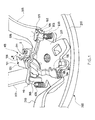
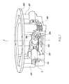
- Figure 1 illustrates a retaining assembly 100 according to the present invention, provided on a steering wheel 200, in particular on the hub 201 of its frame, where driver airbag modules (DABs) are usually mounted.
- the steering wheel 200 comprises a ring portion 202 connected to the hub 201 through a plurality of spokes 203.
- Retaining assembly 100 can be provided directly on the hub 201 or can be mounted on a support which can be fixed to the hub 201, for example a suitable plate.
- the assembly 100 comprises mechanical elements for imposing, at a second side of an airbag module functionaffy assembled with the steering wheel 200, displacements parallel to the steering wheel axis of rotation, imparted to a first side of the module.
- Such mechanical elements may be of a different type, depending on various parameters as, for example, the room available in correspondence of the hub 201, or the airbag module size. What is important for such elements is their capacity to drive an airbag module exclusively parallel to the axis of rotation of the steering wheel, preferably along the axis of the module itself, thus preventing lateral movements.
- the mechanical elements comprise at least a bracket 101, which is hinged to the hub 201.
- the bracket 101 is hinged at its ends 103, 104 and pivots in the direction R.
- the hub 201 or the support plate which eventually joins the assembly 100 to the hub 201, is provided with suitable hinges 301, 302 for supporting rotation of the bracket 101.
- the rotation angle of the bracket 101 is determined by the shape of its ends 103, 104 and by the shape of the hinges 301, 302. Attachment between, respectively, the ends 103, 104 and the hinges 301, 302 is preferably removable to allow easy assembling and disassembling of the assembly 100.
- Each end 103, 104 has a channel 105 which permits insertion of a hinge 301, 302, as illustrated in figure 1.
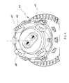
- the bracket 101 can longitudinally slide, as indicated by the direction T of figure 2, so as to be definitely linked to the hinges 301, 302 or separated from the same.
- the hinges 301, 302 may be coupled to the hub 201.
- the hinges 301, 302 are directly obtained by the hub 201 moulding.
- Concerning the bracket 101, it may be obtained by plate bending or moulding of plastic resin or metal.
- bracket 101 is made of a flexible material which permits twisting of the bracket 101 when loaded, displacements transmitted from one end 103 or 104 to the other end 103 or 104 will not be identical but lightly lessened, for example to about the 60%. For this reason the bracket 101 is preferably rigid, although such a flexible material could be adopted for economic reasons.
- the bracket 101 also provides means for engaging an airbag module, for example a traditional driver airbag module DAB.
- Such engaging means can be of a traditional type, i.e. screws, nuts, pins, teeth, etc., but preferably they allow snap-in attachment to the airbag module.
- the bracket 101 is provided, at each end 103, 104, with a tab 106 which engages a suitable cavity on the module. In this way, once a DAB module is snapped in place by the bracket 101, any vertical movement imparted on a side of the module in correspondence of end 103, causing its rotation, is equally transmitted to the diametrically opposite side of said module by the end 104.
- the assembly 100 may provide suitable guides, bearings, etc.. Moreover, position of such mechanical means can be arranged in order to meet assembling needs or customer's requests.
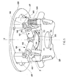
- the assembly 100 comprises a second bracket 102 which is crisscross mounted with respect to the first bracket 101, as shown in figures 1-7. In this way, a DAB module 400 (figure 3) can be driven by the assembly 100 exclusively in a direction parallel to the axis of rotation Z of the steering wheel, with no possibilities for the module 400 to tilt laterally.
- the assembly 100 drives the DAB module 400 in a direction parallel to the axis of rotation Z of the steering wheel due to the displacement imparted at the end 110 of the bracket 102 being equally (rigidly) transmitted both to the end 109, which engages the side (area P3) of the module 400 diametrically opposite to that corresponding to the area P1, and to the ends 103 and 104 of the bracket 101 (corresponding to areas P2 and P4), which also engage the module 400.
- the brackets 101 and 102 pivot on respective hinges 301, 302, 303, 304, thus allowing the module 400 to move parallel to the axis of rotation Z of the steering wheel and reach its working position corresponding to the actuation of the horn of the vehicle provided with the steering wheel 200.
- Operation of the assembly 100 does not change if the driver pushes an area P2 differently located on the module 400: only vertical components of movements imparted to a side of the module 400 will be equally transmitted by the brackets 101 and 102 to the diametrically opposite side of the same module 400.
- the DAB module 400 is returned to its resting position by one ore more resilient elements.
- the resilient elements are two springs 600.
- the retaining assembly according to the invention provides constant horn activation loads, i.e. the loads necessary to close the electrical circuit controlling the horn.
- constant horn activation loads i.e. the loads necessary to close the electrical circuit controlling the horn.
- the driver may push on the module 400, it will provide constant horn performances.
- possibilities of failures in activating the horn by a driver are highly reduced and there is no need for large gaps in the steering wheel coverings to compensate amplifications of module movements.
- Assembly 100 provides means for avoiding the brackets 101 and 102 from disengaging the hinges 301, 302, 303, 304.
- the brackets 101 and 102 may be connected by way of at least a resilient element 500 which keeps the ends 103, 104, 109, 110 of the brackets 101 and 102 in position.
- the resilient element 500 is a wire spring attached, in a removable way, to ends 103 and 110 of the brackets 101 and 102.
- the assembly 100 provides a single switch S, located (see figure 1) on the periphery of the hub 201, in correspondence of the travel height of the module 400. During horn actuation, the switch S is pressed by module 400, thus actuating the vehicle horn.
- FIG 4 shows a particular DAB module 400 which can be easily retained by an assembly 100.
- the module 400 provides, at its bottom, a plurality of legs 401, preferably each leg 401 being located so to overlay one of the ends 103, 104, 109, 110 of the brackets when the module 400 is coupled to the assembly 100.
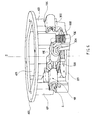
- Figure 5 schematically illustrates how the module 400 (only its bottom is shown) can be snapped into the assembly 100.
- each leg 401 is put into contact with a tab 106 of an end 103, 104, 109, 110 of a bracket, in such a way that the tab 106 is aligned with a suitable groove 402 provided on the legs 401.
- the tabs 106 snap into groves 402 thus retaining the module 400 in its resting position, as illustrated in figure 6.
- Figure 7 illustrates the module 400 in its working position, corresponding to the switch S being operated by a leg 401, i.e. to the horn actuation.
- brackets 101, 102 While engaging the module 400 with the assembly 100, i.e. while pushing the module 400 so that the tabs 106 enter the grooves 402, the brackets 101, 102 are first pivoted downwardly toward the hub 201. Then the brackets 101, 102 can slide along their axis (see direction T of figure 2 for bracket 102) in order to mismatch the channels 105 with respective hinges 301, 302, 303, or 304. Sliding of the brackets 101, 102 is automatically carried out by the resilient element 500, i.e. by the wire spring. In this position the brackets 101, 102 cannot pivot upwardly over the module 400 resting position. The wire spring 500 or any other suitable means will keep the brackets 101, 102 in position, thus avoiding incidental disengagement of the module 400.
- Disengagement of the DAB module 400 can be accomplished by sliding each bracket 101, 102 along its axis, overcoming the resilient element 500 resistance, until the channel 105, provided on each bracket end 103, 104, 109, 110, is aligned with the respective hinge 301, 302, 303, or 304. In this position the brackets 101, 102 can rotate (see direction R of figure 1 for bracket 101) upwardly over the module 400 resting position until each tab 106 exits the respective groove 402, thus permitting separation of the module 400 from the steering wheel hub 201.
- Assembly 100 may provide a traditional attachment with the related DAB module, different from the disclosed one.
- the disclosed attachment provides no screws, neither pins or other means which make the module 400 assembly more complicated or time consuming.
- it is an advantageous feature of the invention that to provide an easy in-line assembly which can be accomplished, for example at the assembly line of the vehicle, simply by inserting module 400 onto hub 201 and pressing until brackets 101 and 102 snap on module 400.
- the assembly 100 may provide brackets 101 and 102 hinged to the DAB module 400 and grooves 402 arranged on the steering wheel hub 201. Also such embodiment provides an easy in-line assembly of the module 400 onto the steering wheel 200.
Landscapes
- Engineering & Computer Science (AREA)
- Mechanical Engineering (AREA)
- Chemical & Material Sciences (AREA)
- Combustion & Propulsion (AREA)
- Transportation (AREA)
- Air Bags (AREA)
- Steering Controls (AREA)
Priority Applications (7)
| Application Number | Priority Date | Filing Date | Title |
|---|---|---|---|
| EP04425334A EP1595754B1 (fr) | 2004-05-10 | 2004-05-10 | Assemblage d'un module de coussin gonflable sur un volant |
| DE602004014253T DE602004014253D1 (de) | 2004-05-10 | 2004-05-10 | Baugruppe mit einem Lenkrad und einem Gassackmodul |
| AT04425334T ATE397540T1 (de) | 2004-05-10 | 2004-05-10 | Baugruppe mit einem lenkrad und einem gassackmodul |
| US11/092,279 US7398994B2 (en) | 2004-05-10 | 2005-03-29 | Assembly for retaining an airbag module to a steering wheel |
| JP2005127514A JP4027947B2 (ja) | 2004-05-10 | 2005-04-26 | エアバッグモジュールをステアリングホイールに保持するための組立体 |
| CNB2005100714977A CN1326725C (zh) | 2004-05-10 | 2005-05-09 | 将气囊组合部件保持于方向盘用的组件 |
| KR1020050038549A KR100623839B1 (ko) | 2004-05-10 | 2005-05-09 | 에어백 모듈과 스티어링 휠의 조립체 |
Applications Claiming Priority (1)
| Application Number | Priority Date | Filing Date | Title |
|---|---|---|---|
| EP04425334A EP1595754B1 (fr) | 2004-05-10 | 2004-05-10 | Assemblage d'un module de coussin gonflable sur un volant |
Publications (2)
| Publication Number | Publication Date |
|---|---|
| EP1595754A1 true EP1595754A1 (fr) | 2005-11-16 |
| EP1595754B1 EP1595754B1 (fr) | 2008-06-04 |
Family
ID=34932487
Family Applications (1)
| Application Number | Title | Priority Date | Filing Date |
|---|---|---|---|
| EP04425334A Expired - Lifetime EP1595754B1 (fr) | 2004-05-10 | 2004-05-10 | Assemblage d'un module de coussin gonflable sur un volant |
Country Status (7)
| Country | Link |
|---|---|
| US (1) | US7398994B2 (fr) |
| EP (1) | EP1595754B1 (fr) |
| JP (1) | JP4027947B2 (fr) |
| KR (1) | KR100623839B1 (fr) |
| CN (1) | CN1326725C (fr) |
| AT (1) | ATE397540T1 (fr) |
| DE (1) | DE602004014253D1 (fr) |
Cited By (1)
| Publication number | Priority date | Publication date | Assignee | Title |
|---|---|---|---|---|
| US7380817B2 (en) | 2005-03-29 | 2008-06-03 | Key Safety Systems, Inc. | Assembly for retaining an airbag module to a steering wheel |
Families Citing this family (26)
| Publication number | Priority date | Publication date | Assignee | Title |
|---|---|---|---|---|
| DE20303303U1 (de) * | 2003-02-28 | 2003-07-03 | TRW Automotive Safety Systems GmbH, 63743 Aschaffenburg | Gassackmodul |
| US7490852B2 (en) * | 2005-03-21 | 2009-02-17 | Delphi Technologies, Inc. | Apparatus and method for providing a horn contact mechanism |
| DE202005013383U1 (de) * | 2005-08-24 | 2006-02-09 | Trw Automotive Safety Systems Gmbh | Fahrzeuglenkrad mit Gassackmodul |
| ES2301341B1 (es) * | 2006-03-13 | 2009-05-01 | Dalphi Metal España S.A. | Volante de automovil con airbag integrado. |
| US7980590B2 (en) | 2008-03-19 | 2011-07-19 | Amsafe, Inc. | Inflatable personal restraint systems having web-mounted inflators and associated methods of use and manufacture |
| US7665761B1 (en) | 2008-03-27 | 2010-02-23 | Amsafe, Inc. | Inflatable personal restraint systems and associated methods of use and manufacture |
| WO2010063849A1 (fr) * | 2008-12-05 | 2010-06-10 | Takata-Petri Ag | Ensemble volant d'un véhicule automobile |
| JP5389544B2 (ja) * | 2009-06-26 | 2014-01-15 | オートリブ ディベロップメント エービー | 車両用エアバッグのマウント構造 |
| JP5432011B2 (ja) * | 2010-03-12 | 2014-03-05 | 芦森工業株式会社 | エアバッグ装置の取付部構造 |
| US8469397B2 (en) | 2011-04-13 | 2013-06-25 | Amsafe, Inc. | Stitch patterns for restraint-mounted airbags and associated systems and methods |
| US8376398B2 (en) * | 2011-07-12 | 2013-02-19 | Tk Holdings Inc. | Airbag and horn switch module and method of assembly of the module |
| US8439398B2 (en) | 2011-07-29 | 2013-05-14 | Amsafe, Inc. | Inflator connectors for inflatable personal restraints and associated systems and methods |
| WO2013070905A1 (fr) | 2011-11-09 | 2013-05-16 | Key Safety Systems Inc. | Ensemble module de coussin de sécurité gonflable de conducteur à encliquetage |
| JP5797770B2 (ja) * | 2011-11-24 | 2015-10-21 | 本田技研工業株式会社 | ステアリングホイールの振動低減構造 |
| US8523220B1 (en) | 2012-03-19 | 2013-09-03 | Amsafe, Inc. | Structure mounted airbag assemblies and associated systems and methods |
| US9511866B2 (en) | 2012-03-19 | 2016-12-06 | Amsafe, Inc. | Structure mounted airbag assemblies and associated systems and methods |
| JP6040884B2 (ja) * | 2012-11-12 | 2016-12-07 | 豊田合成株式会社 | ステアリングホイールの制振構造 |
| JP5933422B2 (ja) * | 2012-12-06 | 2016-06-08 | 太平洋工業株式会社 | タイヤバルブユニット |
| CN103129504B (zh) * | 2013-03-07 | 2015-10-14 | 锦州锦恒汽车安全系统有限公司 | 安装在汽车方向盘上的安全气囊卡接装置 |
| KR101449292B1 (ko) * | 2013-06-03 | 2014-10-08 | 현대자동차주식회사 | 스티어링 휠의 혼 스위치 장치 |
| US9352839B2 (en) | 2014-10-02 | 2016-05-31 | Amsafe, Inc. | Active positioning airbag assembly and associated systems and methods |
| US9944245B2 (en) | 2015-03-28 | 2018-04-17 | Amsafe, Inc. | Extending pass-through airbag occupant restraint systems, and associated systems and methods |
| US9925950B2 (en) | 2015-04-11 | 2018-03-27 | Amsafe, Inc. | Active airbag vent system |
| US10604259B2 (en) | 2016-01-20 | 2020-03-31 | Amsafe, Inc. | Occupant restraint systems having extending restraints, and associated systems and methods |
| CN108437925A (zh) * | 2018-03-05 | 2018-08-24 | 瑞安市正普汽车部件有限公司 | 一种气囊游丝 |
| EP3632752A1 (fr) * | 2018-10-05 | 2020-04-08 | Key Safety Systems, Inc. | Ensemble de module airbag conducteur et de volant de direction |
Citations (3)
| Publication number | Priority date | Publication date | Assignee | Title |
|---|---|---|---|---|
| US20020074781A1 (en) * | 2000-12-20 | 2002-06-20 | Trw Automotive Safety Systems Gmbh & Co. Kg | Vehicle steering wheel |
| EP1281586A2 (fr) * | 2001-08-01 | 2003-02-05 | TRW Automotive Safety Systems GmbH & Co. KG | Volant avec module de sac gonflable déplaçable |
| EP1306271A1 (fr) * | 2001-10-25 | 2003-05-02 | Breed Automotive Technology, Inc. | Module d'airbag |
Family Cites Families (22)
| Publication number | Priority date | Publication date | Assignee | Title |
|---|---|---|---|---|
| FR2716857B1 (fr) * | 1994-03-03 | 1997-07-18 | Autoliv Dev | Volant avec dispositif de protection anti-choc à sac gonflable prémonté. |
| DE4429214A1 (de) * | 1994-08-18 | 1996-02-22 | Trw Repa Gmbh | Fahrzeuglenkrad mit einem integrierten Gassack-Rückhaltesystem |
| KR0161313B1 (ko) | 1994-10-31 | 1999-01-15 | 강박광 | 폴리이미드 아미 에스테르 화합물 및 그 제조방법 |
| CN1068837C (zh) * | 1996-01-12 | 2001-07-25 | 丰田合成株式会社 | 气囊装置 |
| US5685559A (en) * | 1996-04-25 | 1997-11-11 | Trw Inc. | Steering wheel with air bag module |
| JP3284355B2 (ja) | 1996-08-06 | 2002-05-20 | 豊田合成株式会社 | ホーンスイッチ構成体 |
| US5765861A (en) * | 1996-08-12 | 1998-06-16 | Morton International, Inc. | Integral steering wheel and airbag module |
| DE29616892U1 (de) * | 1996-09-27 | 1997-01-30 | Trw Occupant Restraint Systems Gmbh, 73551 Alfdorf | Einrichtung zum Befestigen eines Gassackmoduls |
| US5762359A (en) * | 1996-10-02 | 1998-06-09 | General Motors Corporation | Air bag module and steering wheel assembly |
| US5738369A (en) * | 1996-10-09 | 1998-04-14 | Breed Automotive Technology, Inc. | Snap-on air bag and horn switch module |
| US6119545A (en) * | 1996-12-24 | 2000-09-19 | Toyoda Gosei Co., Ltd. | Steering wheel and method of manufacture, and horn switch |
| US6020941A (en) * | 1998-02-12 | 2000-02-01 | Advanced Display Systems, Inc. | Stereographic liquid crystal display employing switchable liquid crystal materials of two polarities in separate channels |
| KR20000040321A (ko) * | 1998-12-17 | 2000-07-05 | 박문규 | 얇은 두께의 에어백이 장착된 트럭용 조향 핸들 |
| CN2335838Y (zh) * | 1998-12-28 | 1999-09-01 | 张根发 | 整体式汽车驾驶员安全气囊装置 |
| JP2001063588A (ja) | 1999-08-31 | 2001-03-13 | Nippon Plast Co Ltd | ステアリングホイール |
| JP2002200982A (ja) | 2000-12-28 | 2002-07-16 | T S Tec Kk | ホーン機構を備えたステアリングホイール |
| DE20106694U1 (de) * | 2001-04-18 | 2001-08-23 | TRW Automotive Safety Systems GmbH & Co. KG, 63743 Aschaffenburg | Baueinheit aus Gassackmodul und Fahrzeuglenkrad |
| US6830263B2 (en) * | 2002-02-08 | 2004-12-14 | Key Safety Systems, Inc. | Method for attaching an airbag module |
| DE10241048B4 (de) * | 2002-08-30 | 2004-07-08 | Takata-Petri Ag | Schalteinrichtung für eine Fahrzeughupe |
| US20050151354A1 (en) * | 2004-01-14 | 2005-07-14 | Takata Corporation | Steering device and airbag system |
| US7159898B2 (en) * | 2004-04-20 | 2007-01-09 | General Motors Corporation | Vehicle air bag module retention system |
| JP4797584B2 (ja) * | 2005-03-16 | 2011-10-19 | タカタ株式会社 | エアバッグ装置付きステアリングホイール |
-
2004
- 2004-05-10 EP EP04425334A patent/EP1595754B1/fr not_active Expired - Lifetime
- 2004-05-10 DE DE602004014253T patent/DE602004014253D1/de not_active Expired - Lifetime
- 2004-05-10 AT AT04425334T patent/ATE397540T1/de not_active IP Right Cessation
-
2005
- 2005-03-29 US US11/092,279 patent/US7398994B2/en not_active Expired - Fee Related
- 2005-04-26 JP JP2005127514A patent/JP4027947B2/ja not_active Expired - Fee Related
- 2005-05-09 KR KR1020050038549A patent/KR100623839B1/ko not_active Expired - Fee Related
- 2005-05-09 CN CNB2005100714977A patent/CN1326725C/zh not_active Expired - Fee Related
Patent Citations (3)
| Publication number | Priority date | Publication date | Assignee | Title |
|---|---|---|---|---|
| US20020074781A1 (en) * | 2000-12-20 | 2002-06-20 | Trw Automotive Safety Systems Gmbh & Co. Kg | Vehicle steering wheel |
| EP1281586A2 (fr) * | 2001-08-01 | 2003-02-05 | TRW Automotive Safety Systems GmbH & Co. KG | Volant avec module de sac gonflable déplaçable |
| EP1306271A1 (fr) * | 2001-10-25 | 2003-05-02 | Breed Automotive Technology, Inc. | Module d'airbag |
Cited By (2)
| Publication number | Priority date | Publication date | Assignee | Title |
|---|---|---|---|---|
| US7380817B2 (en) | 2005-03-29 | 2008-06-03 | Key Safety Systems, Inc. | Assembly for retaining an airbag module to a steering wheel |
| EP1958829A1 (fr) * | 2007-02-13 | 2008-08-20 | Key Safety Systems, Inc. | Assemblage pour maintenir un module d'airbag au volant de direction |
Also Published As
| Publication number | Publication date |
|---|---|
| US7398994B2 (en) | 2008-07-15 |
| ATE397540T1 (de) | 2008-06-15 |
| KR100623839B1 (ko) | 2006-09-13 |
| US20050248135A1 (en) | 2005-11-10 |
| KR20060045985A (ko) | 2006-05-17 |
| JP4027947B2 (ja) | 2007-12-26 |
| JP2005319991A (ja) | 2005-11-17 |
| EP1595754B1 (fr) | 2008-06-04 |
| CN1695987A (zh) | 2005-11-16 |
| DE602004014253D1 (de) | 2008-07-17 |
| CN1326725C (zh) | 2007-07-18 |
Similar Documents
| Publication | Publication Date | Title |
|---|---|---|
| EP1595754B1 (fr) | Assemblage d'un module de coussin gonflable sur un volant | |
| EP1958829B1 (fr) | Assemblage pour maintenir un module d'airbag au volant de direction | |
| EP2789262B1 (fr) | Meuble d'assise réglable avec un agencement de commutateur manuel et procédé d'assemblage d'un tel meuble | |
| EP0269082B1 (fr) | Carter pour élément de servomoteur d'un rétroviseur | |
| US5738369A (en) | Snap-on air bag and horn switch module | |
| KR102576172B1 (ko) | 차량용 시트 스위블 장치 | |
| CA3059183C (fr) | Ensemble de commutation et d'utilisation d'un interrupteur | |
| JP4097909B2 (ja) | モータ駆動の乗物用シート調節装置 | |
| EP1147939A2 (fr) | Repose-pieds motorisé pour siège | |
| WO1995021339A1 (fr) | Mecanisme de commande d'orientation | |
| AU2003246334A1 (en) | Adjustment device of electric power mirrors | |
| WO2002058969A1 (fr) | Module de coussin gonflable avec contacteur d'avertisseur sonore | |
| US20050061639A1 (en) | Switch stabilizer | |
| EP0702385A1 (fr) | Dispositif de commande manuel multifunction | |
| US7189111B2 (en) | Stand-off bracket for securing a wire harness connector assembly to DC electric motor and associated method | |
| JP2006040579A (ja) | プッシュツマミのがたつき防止構造 | |
| US20260004982A1 (en) | Switch assembly with cantilever | |
| KR100346068B1 (ko) | 자동차의 백미러 조정 스위치 | |
| EP1316872B1 (fr) | Eléments de liaison pour commandes de véhicules automobiles tels que chariots élévateurs | |
| EP1418603A1 (fr) | Dispositif de commutation | |
| KR20010105883A (ko) | 조향컬럼의 틸트장치 | |
| KR20210010112A (ko) | 차량용 턴 시그널 스위치 장치 | |
| JP2005129302A (ja) | スイッチユニット | |
| KR20000009705U (ko) | 조립 및 분해가 용이한 카 오디오용 작동버튼 | |
| KR20000010686U (ko) | 카오디오의 컨트롤패널용 작동노브 |
Legal Events
| Date | Code | Title | Description |
|---|---|---|---|
| PUAI | Public reference made under article 153(3) epc to a published international application that has entered the european phase |
Free format text: ORIGINAL CODE: 0009012 |
|
| AK | Designated contracting states |
Kind code of ref document: A1 Designated state(s): AT BE BG CH CY CZ DE DK EE ES FI FR GB GR HU IE IT LI LU MC NL PL PT RO SE SI SK TR |
|
| AX | Request for extension of the european patent |
Extension state: AL HR LT LV MK |
|
| 17P | Request for examination filed |
Effective date: 20060412 |
|
| AKX | Designation fees paid |
Designated state(s): AT BE BG CH CY CZ DE DK EE ES FI FR GB GR HU IE IT LI LU MC NL PL PT RO SE SI SK TR |
|
| 17Q | First examination report despatched |
Effective date: 20060818 |
|
| 17Q | First examination report despatched |
Effective date: 20060818 |
|
| GRAP | Despatch of communication of intention to grant a patent |
Free format text: ORIGINAL CODE: EPIDOSNIGR1 |
|
| GRAS | Grant fee paid |
Free format text: ORIGINAL CODE: EPIDOSNIGR3 |
|
| GRAA | (expected) grant |
Free format text: ORIGINAL CODE: 0009210 |
|
| AK | Designated contracting states |
Kind code of ref document: B1 Designated state(s): AT BE BG CH CY CZ DE DK EE ES FI FR GB GR HU IE IT LI LU MC NL PL PT RO SE SI SK TR |
|
| REG | Reference to a national code |
Ref country code: GB Ref legal event code: FG4D |
|
| REG | Reference to a national code |
Ref country code: CH Ref legal event code: EP |
|
| REF | Corresponds to: |
Ref document number: 602004014253 Country of ref document: DE Date of ref document: 20080717 Kind code of ref document: P |
|
| REG | Reference to a national code |
Ref country code: IE Ref legal event code: FG4D |
|
| PG25 | Lapsed in a contracting state [announced via postgrant information from national office to epo] |
Ref country code: ES Free format text: LAPSE BECAUSE OF FAILURE TO SUBMIT A TRANSLATION OF THE DESCRIPTION OR TO PAY THE FEE WITHIN THE PRESCRIBED TIME-LIMIT Effective date: 20080915 Ref country code: FI Free format text: LAPSE BECAUSE OF FAILURE TO SUBMIT A TRANSLATION OF THE DESCRIPTION OR TO PAY THE FEE WITHIN THE PRESCRIBED TIME-LIMIT Effective date: 20080604 Ref country code: SI Free format text: LAPSE BECAUSE OF FAILURE TO SUBMIT A TRANSLATION OF THE DESCRIPTION OR TO PAY THE FEE WITHIN THE PRESCRIBED TIME-LIMIT Effective date: 20080604 |
|
| PG25 | Lapsed in a contracting state [announced via postgrant information from national office to epo] |
Ref country code: PL Free format text: LAPSE BECAUSE OF FAILURE TO SUBMIT A TRANSLATION OF THE DESCRIPTION OR TO PAY THE FEE WITHIN THE PRESCRIBED TIME-LIMIT Effective date: 20080604 Ref country code: NL Free format text: LAPSE BECAUSE OF FAILURE TO SUBMIT A TRANSLATION OF THE DESCRIPTION OR TO PAY THE FEE WITHIN THE PRESCRIBED TIME-LIMIT Effective date: 20080604 Ref country code: AT Free format text: LAPSE BECAUSE OF FAILURE TO SUBMIT A TRANSLATION OF THE DESCRIPTION OR TO PAY THE FEE WITHIN THE PRESCRIBED TIME-LIMIT Effective date: 20080604 |
|
| NLV1 | Nl: lapsed or annulled due to failure to fulfill the requirements of art. 29p and 29m of the patents act | ||
| PG25 | Lapsed in a contracting state [announced via postgrant information from national office to epo] |
Ref country code: SE Free format text: LAPSE BECAUSE OF FAILURE TO SUBMIT A TRANSLATION OF THE DESCRIPTION OR TO PAY THE FEE WITHIN THE PRESCRIBED TIME-LIMIT Effective date: 20080904 Ref country code: CZ Free format text: LAPSE BECAUSE OF FAILURE TO SUBMIT A TRANSLATION OF THE DESCRIPTION OR TO PAY THE FEE WITHIN THE PRESCRIBED TIME-LIMIT Effective date: 20080604 Ref country code: PT Free format text: LAPSE BECAUSE OF FAILURE TO SUBMIT A TRANSLATION OF THE DESCRIPTION OR TO PAY THE FEE WITHIN THE PRESCRIBED TIME-LIMIT Effective date: 20081104 |
|
| PG25 | Lapsed in a contracting state [announced via postgrant information from national office to epo] |
Ref country code: SK Free format text: LAPSE BECAUSE OF FAILURE TO SUBMIT A TRANSLATION OF THE DESCRIPTION OR TO PAY THE FEE WITHIN THE PRESCRIBED TIME-LIMIT Effective date: 20080604 Ref country code: RO Free format text: LAPSE BECAUSE OF FAILURE TO SUBMIT A TRANSLATION OF THE DESCRIPTION OR TO PAY THE FEE WITHIN THE PRESCRIBED TIME-LIMIT Effective date: 20080604 Ref country code: BE Free format text: LAPSE BECAUSE OF FAILURE TO SUBMIT A TRANSLATION OF THE DESCRIPTION OR TO PAY THE FEE WITHIN THE PRESCRIBED TIME-LIMIT Effective date: 20080604 |
|
| PLBE | No opposition filed within time limit |
Free format text: ORIGINAL CODE: 0009261 |
|
| STAA | Information on the status of an ep patent application or granted ep patent |
Free format text: STATUS: NO OPPOSITION FILED WITHIN TIME LIMIT |
|
| PG25 | Lapsed in a contracting state [announced via postgrant information from national office to epo] |
Ref country code: BG Free format text: LAPSE BECAUSE OF FAILURE TO SUBMIT A TRANSLATION OF THE DESCRIPTION OR TO PAY THE FEE WITHIN THE PRESCRIBED TIME-LIMIT Effective date: 20080904 Ref country code: EE Free format text: LAPSE BECAUSE OF FAILURE TO SUBMIT A TRANSLATION OF THE DESCRIPTION OR TO PAY THE FEE WITHIN THE PRESCRIBED TIME-LIMIT Effective date: 20080604 Ref country code: DK Free format text: LAPSE BECAUSE OF FAILURE TO SUBMIT A TRANSLATION OF THE DESCRIPTION OR TO PAY THE FEE WITHIN THE PRESCRIBED TIME-LIMIT Effective date: 20080604 |
|
| 26N | No opposition filed |
Effective date: 20090305 |
|
| PG25 | Lapsed in a contracting state [announced via postgrant information from national office to epo] |
Ref country code: IT Free format text: LAPSE BECAUSE OF FAILURE TO SUBMIT A TRANSLATION OF THE DESCRIPTION OR TO PAY THE FEE WITHIN THE PRESCRIBED TIME-LIMIT Effective date: 20080604 |
|
| PG25 | Lapsed in a contracting state [announced via postgrant information from national office to epo] |
Ref country code: MC Free format text: LAPSE BECAUSE OF NON-PAYMENT OF DUE FEES Effective date: 20090531 |
|
| REG | Reference to a national code |
Ref country code: CH Ref legal event code: PL |
|
| PG25 | Lapsed in a contracting state [announced via postgrant information from national office to epo] |
Ref country code: LI Free format text: LAPSE BECAUSE OF NON-PAYMENT OF DUE FEES Effective date: 20090531 Ref country code: CH Free format text: LAPSE BECAUSE OF NON-PAYMENT OF DUE FEES Effective date: 20090531 |
|
| PG25 | Lapsed in a contracting state [announced via postgrant information from national office to epo] |
Ref country code: IE Free format text: LAPSE BECAUSE OF NON-PAYMENT OF DUE FEES Effective date: 20090510 |
|
| PGFP | Annual fee paid to national office [announced via postgrant information from national office to epo] |
Ref country code: FR Payment date: 20100525 Year of fee payment: 7 |
|
| PG25 | Lapsed in a contracting state [announced via postgrant information from national office to epo] |
Ref country code: GR Free format text: LAPSE BECAUSE OF FAILURE TO SUBMIT A TRANSLATION OF THE DESCRIPTION OR TO PAY THE FEE WITHIN THE PRESCRIBED TIME-LIMIT Effective date: 20080905 |
|
| PGFP | Annual fee paid to national office [announced via postgrant information from national office to epo] |
Ref country code: GB Payment date: 20100401 Year of fee payment: 7 |
|
| PG25 | Lapsed in a contracting state [announced via postgrant information from national office to epo] |
Ref country code: LU Free format text: LAPSE BECAUSE OF NON-PAYMENT OF DUE FEES Effective date: 20090510 |
|
| PG25 | Lapsed in a contracting state [announced via postgrant information from national office to epo] |
Ref country code: HU Free format text: LAPSE BECAUSE OF FAILURE TO SUBMIT A TRANSLATION OF THE DESCRIPTION OR TO PAY THE FEE WITHIN THE PRESCRIBED TIME-LIMIT Effective date: 20081205 |
|
| PG25 | Lapsed in a contracting state [announced via postgrant information from national office to epo] |
Ref country code: TR Free format text: LAPSE BECAUSE OF FAILURE TO SUBMIT A TRANSLATION OF THE DESCRIPTION OR TO PAY THE FEE WITHIN THE PRESCRIBED TIME-LIMIT Effective date: 20080604 |
|
| PG25 | Lapsed in a contracting state [announced via postgrant information from national office to epo] |
Ref country code: CY Free format text: LAPSE BECAUSE OF FAILURE TO SUBMIT A TRANSLATION OF THE DESCRIPTION OR TO PAY THE FEE WITHIN THE PRESCRIBED TIME-LIMIT Effective date: 20080604 |
|
| PGFP | Annual fee paid to national office [announced via postgrant information from national office to epo] |
Ref country code: DE Payment date: 20110531 Year of fee payment: 8 |
|
| GBPC | Gb: european patent ceased through non-payment of renewal fee |
Effective date: 20110510 |
|
| REG | Reference to a national code |
Ref country code: FR Ref legal event code: ST Effective date: 20120131 |
|
| PG25 | Lapsed in a contracting state [announced via postgrant information from national office to epo] |
Ref country code: FR Free format text: LAPSE BECAUSE OF NON-PAYMENT OF DUE FEES Effective date: 20110531 |
|
| PG25 | Lapsed in a contracting state [announced via postgrant information from national office to epo] |
Ref country code: GB Free format text: LAPSE BECAUSE OF NON-PAYMENT OF DUE FEES Effective date: 20110510 |
|
| REG | Reference to a national code |
Ref country code: DE Ref legal event code: R119 Ref document number: 602004014253 Country of ref document: DE Effective date: 20121201 |
|
| PG25 | Lapsed in a contracting state [announced via postgrant information from national office to epo] |
Ref country code: DE Free format text: LAPSE BECAUSE OF NON-PAYMENT OF DUE FEES Effective date: 20121201 |