EP1595765A1 - Dispositif de tamponnement et/ou de traction, avec générateur d'électricité - Google Patents
Dispositif de tamponnement et/ou de traction, avec générateur d'électricité Download PDFInfo
- Publication number
- EP1595765A1 EP1595765A1 EP05008268A EP05008268A EP1595765A1 EP 1595765 A1 EP1595765 A1 EP 1595765A1 EP 05008268 A EP05008268 A EP 05008268A EP 05008268 A EP05008268 A EP 05008268A EP 1595765 A1 EP1595765 A1 EP 1595765A1
- Authority
- EP
- European Patent Office
- Prior art keywords
- buffer
- pulling
- energy
- kinetic energy
- buffer device
- Prior art date
- Legal status (The legal status is an assumption and is not a legal conclusion. Google has not performed a legal analysis and makes no representation as to the accuracy of the status listed.)
- Withdrawn
Links
- 239000000872 buffer Substances 0.000 title claims abstract description 84
- 230000005611 electricity Effects 0.000 title 1
- 238000004146 energy storage Methods 0.000 claims abstract description 5
- 230000003139 buffering effect Effects 0.000 claims description 16
- 238000006243 chemical reaction Methods 0.000 claims description 5
- 230000008878 coupling Effects 0.000 abstract description 17
- 238000010168 coupling process Methods 0.000 abstract description 17
- 238000005859 coupling reaction Methods 0.000 abstract description 17
- 239000011796 hollow space material Substances 0.000 abstract 1
- 230000003137 locomotive effect Effects 0.000 description 5
- 230000006835 compression Effects 0.000 description 4
- 238000007906 compression Methods 0.000 description 4
- 230000001934 delay Effects 0.000 description 4
- 230000001133 acceleration Effects 0.000 description 3
- 230000008719 thickening Effects 0.000 description 2
- 239000003990 capacitor Substances 0.000 description 1
- 230000002860 competitive effect Effects 0.000 description 1
- 230000001419 dependent effect Effects 0.000 description 1
- 238000006073 displacement reaction Methods 0.000 description 1
- 238000005265 energy consumption Methods 0.000 description 1
- 238000009434 installation Methods 0.000 description 1
- 239000000463 material Substances 0.000 description 1
- 238000000034 method Methods 0.000 description 1
- 238000005457 optimization Methods 0.000 description 1
- 238000009420 retrofitting Methods 0.000 description 1
- 230000035939 shock Effects 0.000 description 1
- 239000004575 stone Substances 0.000 description 1
Images

Classifications
-
- B—PERFORMING OPERATIONS; TRANSPORTING
- B61—RAILWAYS
- B61D—BODY DETAILS OR KINDS OF RAILWAY VEHICLES
- B61D43/00—Devices for using the energy of the movements of the vehicles
-
- B—PERFORMING OPERATIONS; TRANSPORTING
- B61—RAILWAYS
- B61G—COUPLINGS; DRAUGHT AND BUFFING APPLIANCES
- B61G11/00—Buffers
- B61G11/18—Details
-
- B—PERFORMING OPERATIONS; TRANSPORTING
- B61—RAILWAYS
- B61G—COUPLINGS; DRAUGHT AND BUFFING APPLIANCES
- B61G9/00—Draw-gear
- B61G9/20—Details; Accessories
-
- Y—GENERAL TAGGING OF NEW TECHNOLOGICAL DEVELOPMENTS; GENERAL TAGGING OF CROSS-SECTIONAL TECHNOLOGIES SPANNING OVER SEVERAL SECTIONS OF THE IPC; TECHNICAL SUBJECTS COVERED BY FORMER USPC CROSS-REFERENCE ART COLLECTIONS [XRACs] AND DIGESTS
- Y02—TECHNOLOGIES OR APPLICATIONS FOR MITIGATION OR ADAPTATION AGAINST CLIMATE CHANGE
- Y02T—CLIMATE CHANGE MITIGATION TECHNOLOGIES RELATED TO TRANSPORTATION
- Y02T30/00—Transportation of goods or passengers via railways, e.g. energy recovery or reducing air resistance
Definitions
- the invention relates to a pulling and / or buffering device between two relatively movable units, in particular freight cars or freight cars.
- Such pulling and / or buffer devices or pulling and / or pushing devices For example, in freight trains between two adjacent car or between a car and the locomotive or a railcar used to the occurring distance changes due to delays (braking, acceleration) or due to cornering etc. compensate.
- an energy supply each wagon would be desirable, for example, an on-board telemetry device (Transmitting or transmitting and receiving device) as part of a Operate telemetry system.
- an on-board telemetry device Transmitting or transmitting and receiving device
- Such a telemetry system as for example in truck freight transport extremely is used successfully, allows an optimization of the paths to be covered, load capacity, capacity etc. and avoid unnecessary downtime and erroneous trips.
- axle generators are known for several decades, in which by the rotation of the axis is generated as part of a generator current, these are added Freight car not or hardly used. Disadvantageously this is instead of the use Conventional standard axes, the installation of special cost-intensive axes necessary, because these axes are part of the generator. In addition, such axle generators prone to external mechanical influences, such as rockfall, etc., which Damage or even failure of the power supply.
- cars could be equipped with a battery or a rechargeable battery to to ensure the power supply for a telemetry device.
- Charging or replacing the discharged battery is maintenance-intensive and In addition, not always guaranteed in time by the large route network, so that the Power supply and hereby the connected device, such as a telemetry device, fails.
- the present invention is therefore based on the object for between two relatively Movable units, especially freight cars, in a simple way a to create self-sufficient energy supply.
- train and / or buffer device which between two relatively movable units, in particular freight cars, is arranged may be at least a part of acting on the pulling and / or buffer device Energy is converted by means of a transducer device into electrical energy, as an energy supply to other facilities, especially telemetry systems (Radio, GPS, GSM etc.) to serve.
- a transducer device using of standard pulling and / or buffering devices (without expensive replacement of axles, etc.) a self-sufficient power supply can be guaranteed.
- the acting kinetic energy in thermal and / or kinetic energy by means of a thermal and / or kinetic Energy storage cached.
- a thermal energy storage already in conventional pulling and / or buffering devices due to the resulting heat loss heated material of the pulling and / or buffer device (Housing, spring, plunger, etc.) is present.
- kinetic memory For example, depending on the force occurring in the respective maximum position latching Spring elements or similar in question, which the energy when needed and in particular more uniform can give.
- a transducer device is at least partially or even completely arranged within the pulling and / or buffer device.
- the transducer device is in the cavity a conventional pulling and / or buffer device used. This is it advantageously possible to use inexpensive standard components, wherein
- existing train and / or buffer devices on simple and inexpensive Can be retrofitted to train and / or buffer devices according to the invention are.
- the transducer device with an electrical Charging device and an electrical storage device, such as a battery, a battery, a capacitor, etc. connected.
- an electrical Charging device and an electrical storage device, such as a battery, a battery, a capacitor, etc. connected.
- a converter device come a variety of energy converters, such as Peltier elements, heat pump (difference in temperature of the pulling and / or buffering device and ambient temperature), piezocrystals, electric generators, in particular linear or rotary generator etc. alone or in any combination in question.
- energy converters such as Peltier elements, heat pump (difference in temperature of the pulling and / or buffering device and ambient temperature), piezocrystals, electric generators, in particular linear or rotary generator etc. alone or in any combination in question.
- the pulling and / or buffering device it is possible to act on the pulling and / or buffering device to convert kinetic energy into electrical energy, as a power supply for any electrical devices, in particular a telemetry device to serve.
- the kinetic energy in any form, especially strong act impulsively on the tension and / or buffer device according to the invention.
- Impacts occur, for example, in the rail freight between the car or a car and the railcar or the locomotive often, for example up to several times per kilometer up.
- tension and / or buffer device is not only can be used in rail transport but applicable in any case in which one Energy supply is lacking or difficult to access and at least two Units move relative to each other. So it would also be conceivable inventive Pulling and / or buffering device in container rows or trains, e.g. at the airport or in warehouses.
- the invention advantageously for Energy generation or energy supply of electrical equipment, in particular telemetry equipment be used.
- carriage-specific data such as Mileage, position, position (e.g., as determined by GPS or GSM), movement information, Cargo information (capacity, type of goods, etc.), operating parameters (wheel bearing temperature, Derailment, etc.) to a processing and control center, in particular be transmitted by radio.
- rail freight transport in particular with regard to capacity utilization, availability, Coordination etc. to optimize.
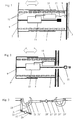
- a buffer or a buffer device in particular a buffer of a train carriage, from a foot 1 of the buffer, which is on a buffer pile 3 is attached.
- a foot 1 of the buffer which is on a buffer pile 3 is attached.
- On this mostly hollow cylindrical foot 1 is also usually a hollow cylindrical Pot 5 of the buffer with a larger inner diameter than the outer diameter of the foot 1, so that the pot 5 on the foot 1 in the longitudinal direction (see double arrow) of the buffer device to move back and forth.
- spring elements 11 for example in the form of a ring spring to a compression of the Counteract buffers with spring force.
- the frontal end of the pot 5 forms a buffer plate 7, which is usually convex is designed to be in contact with a similar buffer of the adjacent wagon And point contact the opposite buffer plates 7 even when curves or Gradient a corresponding movement and displacement of the point contact without wedging to design.
- a buffer plunger 9 which connected to the buffer plate 7 and its center is.
- This buffer plunger 9 has a shorter length than the inner distance between buffer plate 7 and buffer pile 3, in which the spring 11 against compression acts.
- the plunger 9 which at its exposed end, as shown in Fig. 2, has a thickening, for example in the form of a mother, is in cooperation with an arranged in this area sleeve, which in the schematic Drawing is not shown in detail, even with a pulling apart of the buffer over the spring travel of the spring 11 also a falling apart of the spring and the buffer prevented.
- This sleeve or plate is seated at the end of the plunger 9 and is against Sliding down secured by the thickening. In the edge area of the plate or the Sleeve engages the spring 11, so that this spring even when pulling the Buffer is secured against falling apart.
- Such a buffer is usually by a longitudinal guide between the inside of the Pot 5 and outside of the foot 1 secured against rotation or rotation and also has a not shown in the drawing fuse against Pulling the pot 5 from the foot 1 on.
- the aforementioned parts are in a conventional buffer, for example one Freight wagons, standard and therefore already available.
- a buffer after the Invention is in addition to the aforementioned parts a Energywandler worn 13, for example in the form of a linear generator, through which the rod the plunger 9 extends longitudinally movable or is arranged at her.
- a Energywandler worn 13 for example in the form of a linear generator, through which the rod the plunger 9 extends longitudinally movable or is arranged at her.
- the converter device 13 is provided with a charging circuit electrical energy storage device 15, in particular in the form of at least one Accumulator connected so that the converted electrical energy by means of Charging circuit is stored in the battery.
- a charging circuit electrical energy storage device 15 in particular in the form of at least one Accumulator connected so that the converted electrical energy by means of Charging circuit is stored in the battery.
- the memory device 15 via a cable 17 is connected to a connection device 19, which from the outside, for example through the buffer pile 3, is accessible to an electrical device to be connected.
- a connection device 19 which from the outside, for example through the buffer pile 3, is accessible to an electrical device to be connected.
- the electric Connection of the memory device 15 in a different way, for example by the foot. 1 of the buffer to lead to the outside or an electrical device to be supplied within the buffer.
- parts of the storage device 15, in particular the battery or the battery to be arranged outside the buffer, of course, to the remaining inside the buffer parts an electric Connection must be ensured by means of appropriate cable.
- the pulling device or towing hook device illustrated in FIG. 2 differs from the buffer device shown in FIG. 1 essentially through a pot 7 ', which is not designed as a convex plate 7, but as a flat bottom. moreover extends the plunger 9 'of the pulling device in contrast to the plunger 9 of the buffer through the screed 3, wherein at the protruding end of the plunger 9 'a Tow hook 21 is located.
- the pulling device of FIG. 2 by pulling on the hook 21 in the longitudinal direction acted upon by the buffer pile 3 away with a force, the pulling device against the spring force of the spring 11 is compressed. Both in this compression of the Pulling device, as well as an expansion by discharge on the hook 21, is this movement or this kinetic energy as well as in the case of the buffer described in the converter 13 at least partially, for example in the percent or even converted into the per thousand range of kinetic energy into electrical energy and stored in the storage device 15.
- Fig. 3 is described for better understanding of how two pull hooks 21 and 21 ' adjacent wagons or a wagon are coupled to a locomotive.
- the hooks 21 and 21 'each have a first tab 23 and 23', which on the towing hook 21, 21 'is pivotally mounted at one end in the plane of the drawing.
- the opposite End of the tab 23, 23 ' is by means of two threaded rods with opposite Threads 25, 29 or 25 ', 29' and an adjusting screw or adjusting nut 27, 27 'connected to a second tab 31, 31', which in turn at one end is pivotally mounted in the plane of the drawing.
- To connect two hooks it is, as shown in Fig. 3, only necessary, one of the two second tabs 31, 31 ' to put over the other hook 21, 21 ', so that the hook 21, 21' only against train connected to each other, wherein the distance of this connection via the adjusting screw 27 or 27 'is variable.
- FIG. 4 to 6 different types of couplings are shown, in which in each case one or more buffer devices according to FIG. 1 and traction devices according to FIG Fig. 2 are used.
- the coupling shown in Fig. 4 relates to a so-called normal coupling a Regular track, with two adjacent wagons or locomotive and wagon centered above their train (hook) device 37 and 37 'are connected against train. Against pressure the two wagons or their planks 3, 3 'by means of left and right sides or in the in the drawing shown above and below the traction device 37, 37 'arranged, respectively oppositely directed buffers 33, 33', and 35, 35 'coupled.
- the illustrated buffer devices 33, 33 ', 35, 35' and traction devices 37, 37 ' be in the familiar train practice with delays of the entire train or individual Wagons due to different relative movements (acceleration, braking, Differences in incline, etc.) are applied with force, which as explained above in the train and / or buffer devices according to the invention in electrical Energy is converted and stored. Furthermore, forces or different Movements that occur when cornering and by the corresponding the buffer 35 arranged on one side of the middle pulling device 37, 37 ', 35 'compressed or pulled apart (going back to maximum to the starting position without spring force) the buffers of the other side 33, 33 'accordingly expand or be compressed.
- the short coupling of the control track shown in FIG. 5 differs from that shown in FIG. 4 illustrated normal coupling only with respect to the buffer devices, here left and right side or above and below the towing hook device 37, 37 'respectively only one buffer device 34 '(top) and 34 (bottom) is provided.
- the movement processes differ and the respective possible energy conversion and storage at this Close coupling not from the above-described normal coupling according to FIG. 4.
- FIG. 6 shows another, known in narrow gauge railways coupling type, wherein two Car or a car and a locomotive instead of centrally with traction devices in the middle with buffer devices 36, 36 'coupled together against pressure and outboard against train with pulling device 38, 38 '(top) and 39, 39' (bottom) connected are.
- This coupling form principally represents an inversion of that shown in FIG Normal coupling, the movements as well as described above, run and therefore also to an energy conversion and storage in the lead buffer and traction devices according to the invention.
Landscapes
- Engineering & Computer Science (AREA)
- Mechanical Engineering (AREA)
- Transportation (AREA)
- Train Traffic Observation, Control, And Security (AREA)
- Electric Propulsion And Braking For Vehicles (AREA)
Applications Claiming Priority (2)
| Application Number | Priority Date | Filing Date | Title |
|---|---|---|---|
| DE102004023721 | 2004-05-11 | ||
| DE102004023721A DE102004023721B8 (de) | 2004-05-11 | 2004-05-11 | Zug- und/oder Puffervorrichtung |
Publications (1)
| Publication Number | Publication Date |
|---|---|
| EP1595765A1 true EP1595765A1 (fr) | 2005-11-16 |
Family
ID=34559895
Family Applications (1)
| Application Number | Title | Priority Date | Filing Date |
|---|---|---|---|
| EP05008268A Withdrawn EP1595765A1 (fr) | 2004-05-11 | 2005-04-15 | Dispositif de tamponnement et/ou de traction, avec générateur d'électricité |
Country Status (2)
| Country | Link |
|---|---|
| EP (1) | EP1595765A1 (fr) |
| DE (1) | DE102004023721B8 (fr) |
Cited By (4)
| Publication number | Priority date | Publication date | Assignee | Title |
|---|---|---|---|---|
| EP2050647A1 (fr) * | 2007-10-19 | 2009-04-22 | Siemens Aktiengesellschaft | Unité de communication pour un véhicule sur rail et véhicule sur rail correspondant |
| DE102007058602A1 (de) * | 2007-12-04 | 2009-06-18 | Sew-Eurodrive Gmbh & Co. Kg | Antrieb und Verfahren |
| CN112298261A (zh) * | 2020-11-03 | 2021-02-02 | 温州职业技术学院 | 一种安全可靠的轨道交通车厢对接装置 |
| CN115288964A (zh) * | 2022-09-26 | 2022-11-04 | 西南交通大学 | 一种应用于货运列车自供电传感器的车钩缓冲发电装置 |
Families Citing this family (4)
| Publication number | Priority date | Publication date | Assignee | Title |
|---|---|---|---|---|
| DE102016208377A1 (de) | 2016-05-17 | 2017-11-23 | Voith Patent Gmbh | Überwachung eines horizontalen Dämpfungselements für ein Schienenfahrzeug |
| DE102016109263A1 (de) * | 2016-05-20 | 2017-11-23 | Knorr-Bremse Systeme für Schienenfahrzeuge GmbH | Telemetrievorrichtung für ein Schienenfahrzeug |
| FR3081814B1 (fr) * | 2018-05-29 | 2021-08-27 | Sncf Mobilites | Attelage ferroviaire comportant un dispositif de generation d'energie electrique |
| CN120817113B (zh) * | 2025-07-31 | 2026-03-10 | 山东万通液压股份有限公司 | 一种高速列车自供电气液缓冲系统 |
Citations (5)
| Publication number | Priority date | Publication date | Assignee | Title |
|---|---|---|---|---|
| DE163138C (fr) * | ||||
| US3559027A (en) * | 1967-09-27 | 1971-01-26 | Harold B Arsem | Electric shock absorber |
| US4500827A (en) * | 1984-06-11 | 1985-02-19 | Merritt Thomas D | Linear reciprocating electrical generator |
| SU1562517A1 (ru) * | 1988-02-09 | 1990-05-07 | М.Е.Пашнин | Устройство дл рекуперации энергии относительных перемещений двух сцепленных между собой объектов |
| EP1151906A2 (fr) * | 2000-04-26 | 2001-11-07 | Tiefenbach GmbH | Wagon ferroviaire |
Family Cites Families (1)
| Publication number | Priority date | Publication date | Assignee | Title |
|---|---|---|---|---|
| DE4302377C2 (de) * | 1993-01-28 | 1998-08-27 | Erhard Beule | Einrichtung zum Automatisieren des Rangierbetriebes von Schienenfahrzeugen |
-
2004
- 2004-05-11 DE DE102004023721A patent/DE102004023721B8/de not_active Expired - Fee Related
-
2005
- 2005-04-15 EP EP05008268A patent/EP1595765A1/fr not_active Withdrawn
Patent Citations (5)
| Publication number | Priority date | Publication date | Assignee | Title |
|---|---|---|---|---|
| DE163138C (fr) * | ||||
| US3559027A (en) * | 1967-09-27 | 1971-01-26 | Harold B Arsem | Electric shock absorber |
| US4500827A (en) * | 1984-06-11 | 1985-02-19 | Merritt Thomas D | Linear reciprocating electrical generator |
| SU1562517A1 (ru) * | 1988-02-09 | 1990-05-07 | М.Е.Пашнин | Устройство дл рекуперации энергии относительных перемещений двух сцепленных между собой объектов |
| EP1151906A2 (fr) * | 2000-04-26 | 2001-11-07 | Tiefenbach GmbH | Wagon ferroviaire |
Cited By (5)
| Publication number | Priority date | Publication date | Assignee | Title |
|---|---|---|---|---|
| EP2050647A1 (fr) * | 2007-10-19 | 2009-04-22 | Siemens Aktiengesellschaft | Unité de communication pour un véhicule sur rail et véhicule sur rail correspondant |
| DE102007058602A1 (de) * | 2007-12-04 | 2009-06-18 | Sew-Eurodrive Gmbh & Co. Kg | Antrieb und Verfahren |
| CN112298261A (zh) * | 2020-11-03 | 2021-02-02 | 温州职业技术学院 | 一种安全可靠的轨道交通车厢对接装置 |
| CN112298261B (zh) * | 2020-11-03 | 2021-10-01 | 温州职业技术学院 | 一种安全可靠的轨道交通车厢对接装置 |
| CN115288964A (zh) * | 2022-09-26 | 2022-11-04 | 西南交通大学 | 一种应用于货运列车自供电传感器的车钩缓冲发电装置 |
Also Published As
| Publication number | Publication date |
|---|---|
| DE102004023721B3 (de) | 2005-06-09 |
| DE102004023721B8 (de) | 2005-09-22 |
Similar Documents
| Publication | Publication Date | Title |
|---|---|---|
| EP2416986B1 (fr) | Dispositif de transport | |
| EP1312527B1 (fr) | Articulation d'accouplement | |
| DE102016011737B4 (de) | Schienengebundene Achsbaugruppe | |
| EP1289781B1 (fr) | Dispositif pour relier de maniere amovible deux elements d un vehicule disposes en serie, et utilisation de ce dispositif | |
| DE102004023721B3 (de) | Zug- und/oder Puffervorrichtung | |
| EP3164313B2 (fr) | Véhicule ferroviaire réalisé sous la forme d'une rame articulée | |
| DE102013004687A1 (de) | Vorrichtung zum Umbau eines Eisenbahnwagens zu einem Sattelauflieger | |
| DE19543183A1 (de) | Lange Kupplung für Eisenbahnwagen | |
| EP0727338B1 (fr) | Unité de transport ferroviaire pour le transport mixte de conteneurs et de caisses mobiles | |
| DE102016224869A1 (de) | Transportvorrichtung | |
| DE10101470B4 (de) | Zug- und Stossvorrichtung mit Kupplungsarm von Mittelpufferkupplungen | |
| DE102017210478B3 (de) | Schienenfahrzeugwagen | |
| DE19516709B4 (de) | Eisenbahntransporteinheit für den gemischten Transport von Containern und/oder Wechselbehältern und Sattelanhängern | |
| DE60003542T2 (de) | Kupplungseinrichtung für eisenbahnwagen | |
| EP1452418B1 (fr) | Rame de wagons de marchandises | |
| DE102007030098B4 (de) | Fahrerkabine zum lösbaren, stirnseitigen Montieren auf einem schienengebundenen Fahrzeug, schienengebundener Güterwagen und schienengebundenes Zugfahrzeug | |
| EP3109121B1 (fr) | Bati tournant pour vehicules ferroviaire a plusieurs articulations et vehicules ferroviaire a plusieurs articulations | |
| EP2613992B1 (fr) | Véhicule sur rails | |
| EP1329371A1 (fr) | Articulation pour barres d' accouplement d' unités de wagons de marchandise | |
| EP3126206B1 (fr) | Wagon de chemin de fer en plusieurs parties muni d'essieux à écartement variable | |
| DE19507236B4 (de) | Großbehältertragwagen für den gemischten Eisenbahntransport von Containern und Wechselbehältern | |
| DE102011014631A1 (de) | Schienenfahrzeug mit einer Rückholeinrichtung zur Reduzierung des Versatzes zu einem Crashpartner | |
| EP0536433A1 (fr) | Véhicule routier composé de plusieurs unités, notamment pour le transport urbain de personnes | |
| DE10205948B4 (de) | Eisenbahngüterwageneinheit | |
| EP1321342B1 (fr) | Wagon et méthode pour le transport de semi-remorques |
Legal Events
| Date | Code | Title | Description |
|---|---|---|---|
| PUAI | Public reference made under article 153(3) epc to a published international application that has entered the european phase |
Free format text: ORIGINAL CODE: 0009012 |
|
| AK | Designated contracting states |
Kind code of ref document: A1 Designated state(s): AT BE BG CH CY CZ DE DK EE ES FI FR GB GR HU IE IS IT LI LT LU MC NL PL PT RO SE SI SK TR |
|
| AX | Request for extension of the european patent |
Extension state: AL BA HR LV MK YU |
|
| RTI1 | Title (correction) |
Free format text: BUFFER AND/OR TRACTION DEVICE, WITH ELECTRICITY GENERATOR. |
|
| AKX | Designation fees paid | ||
| STAA | Information on the status of an ep patent application or granted ep patent |
Free format text: STATUS: THE APPLICATION IS DEEMED TO BE WITHDRAWN |
|
| 18D | Application deemed to be withdrawn |
Effective date: 20060517 |
|
| REG | Reference to a national code |
Ref country code: DE Ref legal event code: 8566 |