EP1595794A1 - Verfahren und Vorrichtung zum Evakuieren einer Kammer - Google Patents
Verfahren und Vorrichtung zum Evakuieren einer Kammer Download PDFInfo
- Publication number
- EP1595794A1 EP1595794A1 EP05009182A EP05009182A EP1595794A1 EP 1595794 A1 EP1595794 A1 EP 1595794A1 EP 05009182 A EP05009182 A EP 05009182A EP 05009182 A EP05009182 A EP 05009182A EP 1595794 A1 EP1595794 A1 EP 1595794A1
- Authority
- EP
- European Patent Office
- Prior art keywords
- chamber
- vacuum
- gas
- valve
- buffer volume
- Prior art date
- Legal status (The legal status is an assumption and is not a legal conclusion. Google has not performed a legal analysis and makes no representation as to the accuracy of the status listed.)
- Granted
Links
- 238000000034 method Methods 0.000 title claims abstract description 35
- 230000001681 protective effect Effects 0.000 claims abstract description 68
- 238000007789 sealing Methods 0.000 claims abstract description 66
- 239000007789 gas Substances 0.000 claims description 136
- 238000012360 testing method Methods 0.000 claims description 72
- QVGXLLKOCUKJST-UHFFFAOYSA-N atomic oxygen Chemical compound [O] QVGXLLKOCUKJST-UHFFFAOYSA-N 0.000 claims description 57
- 239000001301 oxygen Substances 0.000 claims description 57
- 229910052760 oxygen Inorganic materials 0.000 claims description 57
- 238000004806 packaging method and process Methods 0.000 claims description 54
- 239000011261 inert gas Substances 0.000 claims description 18
- 239000000523 sample Substances 0.000 claims description 12
- 238000012856 packing Methods 0.000 abstract 1
- 235000013372 meat Nutrition 0.000 description 7
- 238000012544 monitoring process Methods 0.000 description 7
- 238000013022 venting Methods 0.000 description 7
- IJGRMHOSHXDMSA-UHFFFAOYSA-N Atomic nitrogen Chemical compound N#N IJGRMHOSHXDMSA-UHFFFAOYSA-N 0.000 description 6
- 238000009423 ventilation Methods 0.000 description 5
- CURLTUGMZLYLDI-UHFFFAOYSA-N Carbon dioxide Chemical compound O=C=O CURLTUGMZLYLDI-UHFFFAOYSA-N 0.000 description 4
- 238000005259 measurement Methods 0.000 description 4
- 239000000203 mixture Substances 0.000 description 4
- 239000011888 foil Substances 0.000 description 3
- 230000035515 penetration Effects 0.000 description 3
- 235000013580 sausages Nutrition 0.000 description 3
- 229910002092 carbon dioxide Inorganic materials 0.000 description 2
- 239000001569 carbon dioxide Substances 0.000 description 2
- 230000007547 defect Effects 0.000 description 2
- 230000002950 deficient Effects 0.000 description 2
- 238000011065 in-situ storage Methods 0.000 description 2
- 238000009434 installation Methods 0.000 description 2
- 238000009448 modified atmosphere packaging Methods 0.000 description 2
- 229910052757 nitrogen Inorganic materials 0.000 description 2
- 230000002829 reductive effect Effects 0.000 description 2
- 238000009461 vacuum packaging Methods 0.000 description 2
- MYMOFIZGZYHOMD-UHFFFAOYSA-N Dioxygen Chemical compound O=O MYMOFIZGZYHOMD-UHFFFAOYSA-N 0.000 description 1
- 206010061218 Inflammation Diseases 0.000 description 1
- 108010062374 Myoglobin Proteins 0.000 description 1
- 102000036675 Myoglobin Human genes 0.000 description 1
- XAGFODPZIPBFFR-UHFFFAOYSA-N aluminium Chemical compound [Al] XAGFODPZIPBFFR-UHFFFAOYSA-N 0.000 description 1
- 229910052782 aluminium Inorganic materials 0.000 description 1
- 230000001580 bacterial effect Effects 0.000 description 1
- 230000003385 bacteriostatic effect Effects 0.000 description 1
- 230000015572 biosynthetic process Effects 0.000 description 1
- 230000000903 blocking effect Effects 0.000 description 1
- 238000009530 blood pressure measurement Methods 0.000 description 1
- 230000006835 compression Effects 0.000 description 1
- 238000007906 compression Methods 0.000 description 1
- 230000001276 controlling effect Effects 0.000 description 1
- 230000001419 dependent effect Effects 0.000 description 1
- 230000001066 destructive effect Effects 0.000 description 1
- 235000013305 food Nutrition 0.000 description 1
- 238000003958 fumigation Methods 0.000 description 1
- 230000002538 fungal effect Effects 0.000 description 1
- 238000002309 gasification Methods 0.000 description 1
- 230000004054 inflammatory process Effects 0.000 description 1
- 230000002401 inhibitory effect Effects 0.000 description 1
- 238000003780 insertion Methods 0.000 description 1
- 230000037431 insertion Effects 0.000 description 1
- 230000000670 limiting effect Effects 0.000 description 1
- 239000000314 lubricant Substances 0.000 description 1
- 239000002480 mineral oil Substances 0.000 description 1
- 235000010446 mineral oil Nutrition 0.000 description 1
- JCXJVPUVTGWSNB-UHFFFAOYSA-N nitrogen dioxide Inorganic materials O=[N]=O JCXJVPUVTGWSNB-UHFFFAOYSA-N 0.000 description 1
- 108010050846 oxymyoglobin Proteins 0.000 description 1
- 239000004033 plastic Substances 0.000 description 1
- 239000002985 plastic film Substances 0.000 description 1
- 229920006255 plastic film Polymers 0.000 description 1
- 230000003449 preventive effect Effects 0.000 description 1
- 238000012545 processing Methods 0.000 description 1
- 239000001044 red dye Substances 0.000 description 1
- 235000020989 red meat Nutrition 0.000 description 1
- 230000001105 regulatory effect Effects 0.000 description 1
- 238000005070 sampling Methods 0.000 description 1
Images

Classifications
-
- B—PERFORMING OPERATIONS; TRANSPORTING
- B65—CONVEYING; PACKING; STORING; HANDLING THIN OR FILAMENTARY MATERIAL
- B65B—MACHINES, APPARATUS OR DEVICES FOR, OR METHODS OF, PACKAGING ARTICLES OR MATERIALS; UNPACKING
- B65B31/00—Packaging articles or materials under special atmospheric or gaseous conditions; Adding propellants to aerosol containers
- B65B31/02—Filling, closing, or filling and closing, containers or wrappers in chambers maintained under vacuum or superatmospheric pressure or containing a special atmosphere, e.g. of inert gas
Definitions
- the invention relates to a method and an apparatus for evacuating a Protective gas-fillable chamber, in particular a sealing chamber of a packaging machine, as for the packaging of meat and sausage products is used.
- Carbon dioxide CO 2
- Nitrogen N 2
- gas mixtures of these two components are often used in different compositions.
- the fresh meat packaging under a protective atmosphere with oxygen content is another Procedure that compared to the pure vacuum packaging and the o.g. packaging under inert atmosphere (nitrogen) or nitrogen / carbon dioxide mixtures increasingly important.
- An infeed conveyor clocks the machine through a set of trays fed.
- the number of trays per batch depends on the capacity a seal chamber in which the trays are evacuated.
- the insertion of the to be packed Product is done manually by staff next to the inlet line.
- To Loading the product the batch is transported in the seal chamber.
- From a above the sealing chamber arranged film roll is the top film guided over the shells.
- Two chamber halves (upper and lower tool) are pneumatically closed.
- the sealing chamber is pre-evacuated to a certain pressure. This is followed by the back-venting of the sealing chamber with inert gas up to Atmospheric pressure. Even during the gassing process, the top film on the dish is sealed and punched out.
- After opening a ventilation valve for pressure equalization with the environment the chamber tool is opened and the Trays are transported to the outlet conveyor of the machine. There is a statistical Monitoring of gas composition by sampling (not non-destructive).
- Disposal of the air in the shells before fumigation (evacuation) can basically be done by different process techniques.
- each packaging machine has its own vacuum pump operated.
- the pump is in immediate Near the seal chamber, if possible installed inside the machine.
- the vacuum generators are two piping systems which simultaneously form the required buffer with the Connected packaging machines. They permanently evacuate the vacuum systems Rough vacuum and fine vacuum, whose dynamic equilibrium pressure on different Level is.
- the sealing chambers are connected via suitable actuators connected to the vacuum station.
- a vacuum central system is for example in EP 0 622 301 B1.
- the use of a vacuum unit recommends when pre-pressures of less than 10 mbar are required and more than about four packaging machines to be connected to a vacuum system.
- the object of the present invention is to provide a method and a device for Evacuation of a fillable with inert gas chamber, in particular a sealing chamber a packaging machine, suggesting the concentration of Shielding gas or a gas component of the protective gas, the vacuum source flows, can be reliably determined.
- determining the concentration of at least one gas component of the protective gas in the atmosphere of the buffer volume is a reliable determination of at least one gas component possible.
- the sensors in particular if the sensors are a measuring device for determining the oxygen concentration in gases are highly pressure dependent, the sensor must include a pressure gauge, by means of which the signal of the measuring device for determining the oxygen concentration is adjusted. With strong pressure fluctuations can take a few seconds pass before you can determine a reliable value.
- the buffer volume ensures that the pressure balance between the buffer volume and the chamber the pressure fluctuation in the buffer volume is relatively low, so that at The analysis of the gas in the buffer volume quickly determines a reliable value can be.
- the process is also suitable for individual disposal, at Each machine has its own vacuum pump as a vacuum source.
- the Pressure curve when evacuating a volume by means of a vacuum pump behaves exponential over time. This means that initially a very large pressure drop whereas, on the other hand, the pressure is only very high after initial pressure drop is slowly reduced. Due to the initial pressure equalization of the chamber with The buffer volume is initially guaranteed a rapid pressure drop. thereupon the remaining pressure drop is achieved by means of a vacuum pump, this being clear slower, so that the pressure-sensitive sensor only slightly is influenced by pressure fluctuations and delivers reliable values immediately.
- the buffer volume temporarily stores the gas initially from the chamber was evacuated.
- the chamber during the determination of the concentration at least one Gas component of the protective gas in the atmosphere of the buffer volume the chamber temporarily connected to a vacuum source for evacuation.
- a reliable signal is detected by the sensor without the cycle time of the method is reduced.
- the procedure does not have to wait for the reliable one Signals rest.
- vacuum central systems leaves thus achieve a high clock frequency of the individual machines and recognize, on which machine a defect has occurred.
- the vacuum source may comprise a vacuum reservoir, wherein the continuously Concentration of at least one gas component of the protective gas in the atmosphere the vacuum reservoir is determined.
- the vacuum reservoir is advantageous here As with conventional vacuum central systems many times larger than that Volume of the chamber, allowing at a pressure equalization between the chamber and the vacuum reservoir only very small pressure fluctuations in the vacuum reservoir occur, so that the sensor in the vacuum reservoir continuously reliable values reproduces. Thus, in addition to monitoring the individual machines monitoring the vacuum central system ensures.
- the protective gas is gas having an oxygen concentration over the Used oxygen concentration of air and in determining the concentration at least one gas component of the protective gas determines the oxygen concentration.
- Determining the concentration of at least one gas component of the protective gas in the atmosphere of the flowing out of the chamber during evacuation Gas can after evacuating the chamber, the buffer volume by means of the vacuum pump be evacuated, with the concentration of at least one gas component of the protective gas in the during the pre-evacuation from the buffer volume flowing gas is determined.
- the flowing out of the chamber Gas reliably analyzes what then cached in the buffer volume Gas is reliably analyzed, since the pressure in the buffer volume to the pressure in the chamber after the pressure equalization corresponds and thus when evacuating the Buffer volume also a slow pressure drop takes place, the sensor only negligibly influenced.
- the object is further encompassed by a device for evacuating a chamber which can be filled with protective gas, in particular a sealing chamber of a packaging machine a buffer volume connectable to the chamber and controlled such that the buffer volume is evacuated prior to connection to the chamber and then temporarily connected to the chamber for pre-evacuation thereof; a vacuum source connectable to evacuate the chamber and controlled so as to be temporarily connected thereto after pre-evacuating the chamber; a sensor for determining the concentration of at least one gas component of the protective gas in the atmosphere of the buffer volume or a supply line to the vacuum source, solved.
- a device for evacuating a chamber which can be filled with protective gas, in particular a sealing chamber of a packaging machine a buffer volume connectable to the chamber and controlled such that the buffer volume is evacuated prior to connection to the chamber and then temporarily connected to the chamber for pre-evacuation thereof; a vacuum source connectable to evacuate the chamber and controlled so as to be temporarily connected thereto after pre-evacuating the chamber; a sensor for determining the concentration of
- a protective gas source is provided, which is connectable to the chamber and is controlled so that they after the evacuation of the chamber with this temporarily connected is.
- the senor is arranged in the buffer volume and a provided by the buffer volume separate vacuum source, wherein the vacuum source may have a vacuum reservoir.
- the vacuum source comprises a vacuum reservoir whose Volume is many times greater than the chamber volume and by means of a or more central vacuum pumps is evacuated.
- the vacuum reservoir further sensor for determining the concentration at least a gas component of the protective gas in the atmosphere of the vacuum reservoir be arranged.
- the device may be provided such that a vacuum supply line for connecting Chamber provided with the vacuum source is that a vacuum valve in the Vacuum feed line for shutting off the same is provided that a test chamber is provided, which represents the buffer volume and via a test line with the Vacuum feed line is connectable, with the test line between the vacuum valve and the chamber valve opens into the vacuum supply line that a sensor for the determination the concentration of at least one gas component of the protective gas in the Atmosphere of the test chamber is provided that a test chamber valve in the test line is provided for shutting off the same and that a protective gas valve in the Shielding gas supply to shut off the same and a controller for controlling the Valve is provided.
- a chamber valve in the vacuum supply line is provided for shutting off the same.
- the protective gas source connectable to the chamber via a protective gas supply line.
- the test chamber can also have a test chamber supply line with the vacuum supply line is connectable, wherein the für Psychiasis, and the vacuum source opens into the vacuum supply line.
- a test chamber valve is provided for shutting off the educattingzu effet.
- the senor is in a supply line to the vacuum source, provided in the form of a vacuum pump.
- the vacuum source provided in the form of a vacuum pump.
- the object is further encompassed by a device for evacuating a chamber which can be filled with protective gas, in particular a sealing chamber of a packaging machine a buffer volume that is part of a vacuum source and that is connectable to evacuate the chamber and that is controlled such that the buffer volume is pre-evacuated prior to connection to the chamber and then temporarily connected to the chamber, a sensor for determining the concentration of at least one gas component of the protective gas in the atmosphere of the buffer volume of the vacuum source which is arranged in the buffer volume, dissolved.
- a device for evacuating a chamber which can be filled with protective gas in particular a sealing chamber of a packaging machine a buffer volume that is part of a vacuum source and that is connectable to evacuate the chamber and that is controlled such that the buffer volume is pre-evacuated prior to connection to the chamber and then temporarily connected to the chamber, a sensor for determining the concentration of at least one gas component of the protective gas in the atmosphere of the buffer volume of the vacuum source which is arranged in the buffer volume, dissolved.
- a protective gas source is provided, which can be connected to the chamber is and is controlled so that after evacuating the chamber with this temporarily connected.
- the sensor has to determine the concentration of at least one gas component of the protective gas in the atmosphere, preferably an oxygen probe.
- FIG. 1 shows a vacuum central installation 1, a first packaging machine 2 and a second packaging machine 3. As will be explained later, it is in the vacuum central system 1 to a two-stage vacuum central plant, the first packaging machine 2 disposed of one stage and the second packaging machine 3 is disposed of in two stages.
- the first packaging machine 2 comprises a sealing chamber 4 for creating Modified atmosphere packaging.
- the sealing chamber 4 usually comprises two mold halves, which can be hermetically sealed against each other and a room form, which can be evacuated.
- a Lower foil or a shell arranged in which lies the product to be packaged. about the lower film or the shell is placed a top film, which after evacuation and possibly after the gasification with protective gas on the lower film or the shell is welded.
- the sealing chamber 4 is connected to the vacuum central system 1 via a vacuum feed line 5 connected.
- a chamber valve 6 for blocking the vacuum supply line 5 provided.
- a pressure transducer. 7 provided in order to determine the internal pressure of the sealing chamber 4 can.
- the sealing chamber 4 is also a protective gas supply 8 with a protective gas source 9 connected.
- a protective gas source 9 Starting from the protective gas source 9 are in the inert gas supply line 8 a pressure limiting valve 10, a pressure regulating valve 11 and a protective gas valve 12 provided in the form of a switching valve.
- the sealing chamber 4 is provided with a venting / venting valve 13 for venting and venting the sealing chamber 4 connected.
- the central vacuum unit 1 comprises a rough vacuum reservoir 14 and a fine vacuum reservoir 15.
- the vacuum reservoirs 14, 15 each have a volume, that corresponds to a multiple of the volume of the sealing chamber 4.
- In the rough vacuum reservoir 14 there is usually a pressure of 30 mbar to 40 mbar.
- In the fine vacuum reservoir 15 is usually a pressure of 1 mbar to 10 mbar.
- a first sensor 26th provided, the first oxygen probe 27 and a first pressure transducer 28 includes.
- a second sensor 29 is provided, a second oxygen probe 30 and a second pressure transducer 31 having.
- inert gas packaging When inert gas packaging is first a bottom foil or a shell with the to be packaged good as well as a top film introduced into the open seal chamber 4. Then, the sealing chamber 4 is hermetically sealed, wherein the vacuum valve 6, the shielding gas valve 12 and the vent valve 13 initially closed are. Then the chamber valve 6 is opened, so that a pressure equalization between the sealing chamber 4 and the rough vacuum reservoir 14 (with which the sealing chamber 4 is connected), wherein the rough vacuum reservoir 14 serves as a buffer volume.
- the rough vacuum reservoir 14 was previously by means of the vacuum pumps 16, 17 evacuated to a predetermined pressure level.
- the chamber valve 6 is closed again, wherein the chamber valve. 6 can be time-controlled or pressure-controlled. That is, either the pressure is in the sealing chamber 4 measured by means of the pressure transducer 7 and upon reaching a predetermined pressure level, the chamber valve 6 is closed or it is waited for a predetermined period of time.
- the protective gas valve 12 is opened so that the protective gas source 9 is connected to the sealing chamber 4. This can be done by means of the pressure control valve 11 regulate the final pressure in the sealing chamber 4. Then the protective gas valve 12 closed again, the protective gas valve 12 to be pressure-controlled can. Subsequently, the vent valve 13 is opened, so that a pressure equalization the sealing chamber 4 takes place with the ambient pressure and the sealing chamber 4 can be opened to remove the packaging.
- the second packaging machine 3 is corresponding to the first packaging machine 2, with matching components with the same reference numerals are provided. The difference is that the second packaging machine 3 is disposed of in two stages.
- the vacuum supply line 5 splits in the direction of the central vacuum system 1 in a first arm 32 and a second arm 33, respectively separated by a first vacuum valve 34 and a second vacuum valve 35 can be.
- first a rough vacuum in the sealing chamber 4 achieve by the first vacuum valve 34 is opened, so that the sealing chamber 4 is connected to the rough vacuum reservoir 14.
- the second vacuum valve 35 is opened, so that the sealing chamber. 4 is connected to the fine vacuum reservoir 15.
- the further procedure corresponds to that Sequence of the first packaging machine 2.
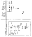
- FIG. 2 shows a vacuum central installation 101 to which a first packaging machine 102 is connected.
- the central vacuum system 101 is like the vacuum central system constructed according to the embodiment of Figure 1.
- the first packaging machine 102 similar to the first packaging machine according to the embodiment constructed according to FIG.
- Other packaging machines can also be connected to the vacuum central system 101 be.
- Components with components of the embodiments according to FIG. 1 match, are provided with reference numerals, which are increased by 100. It Reference is made in this regard to the comments on Figure 1.
- the first packaging machine 102 differs from that according to FIG Figure 1 in that between the chamber valve 106 and the vacuum central system 101 a test chamber 136 as a puller volume to the vacuum supply line 105 in parallel is switched.
- the test chamber 136 is connected via a test line 137 with the vacuum supply line 105 connected and opens between the chamber valve 106 and the junction to the vacuum central system 101 in the vacuum supply line 105.
- the Test chamber 136 via a digitizhatschzu ein 138 with the vacuum supply line 105th connected, the für performingzu ein 138 between the junction of the test line 137 and the connection point to the vacuum central system 101 in the vacuum supply line 105 opens.
- the test line 137 is a first test chamber valve 139th provided for shutting off the test line 137.
- a second test chamber valve 140 for shutting off the scholar 138 provided.
- a vacuum valve 141 is arranged between the two junctions of the test line 137th and the fürcrosch 138 arranged.
- the test chamber 136 For determining at least one gas component of a protective gas in the atmosphere the test chamber 136 is provided in this a third sensor 142, a third oxygen probe 143 and a third pressure transducer 144, wherein the third sensor 142 has the same function as the first sensor 126 and the second sensor 129.
- the third sensor 142 has the same function as the first sensor 126 and the second sensor 129.
- the vacuum reservoirs 114, 115 of the vacuum central system 101 or alternatively only the test chamber 136 may be monitored with sensors. Furthermore, it is possible to provide both cumulatively.
- inert gas packaging When inert gas packaging is first a bottom foil or a shell with the Good to be packaged and a top film in the opened seal chamber 104 introduced. Then, the sealing chamber 104 is hermetically sealed, wherein the Chamber valve 106, the shielding gas valve 112 and the breather valve 113 first are closed. Thereafter, the chamber valve 106 and the first Test chamber valve 139 is opened, wherein the second test chamber valve 140 and the vacuum valve 141 remain closed. Since the packaging machine 102 operated clocked is evacuated, the test chamber 136 from a previous power stroke, so that a pressure equalization between the buffer volume in the form of the test chamber 136th and the sealing chamber 104 takes place. This will produce an atmosphere sample of the Gases removed from the sealing chamber 104.
- the first test chamber valve 139 is closed, so that the Test chamber 136 is airtight completed. Furthermore, the vacuum valve 141 is opened, so that the sealing chamber 104 with the vacuum central system 101 or with the rough vacuum reservoir 14 is connected, so that between the rough vacuum reservoir 114 and the sealing chamber 104, a pressure equalization takes place.
- the volume of the large vacuum reservoir 114 is many times greater than the volume of the sealing chamber 104, finds in the rough vacuum reservoir 114 only a negligible pressure fluctuation.
- the chamber valve 106 is either timed or closed pressure-controlled by the pressure transmitter 107.
- the protective gas valve 112 is opened, so that the protective gas source 109 with the sealing chamber 104 is connected. This can be done by means of the pressure control valve 111 regulate the final pressure in the sealing chamber 104.
- the protective gas valve 112 closed again, the inert gas valve 112 time or pressure controlled can be.
- the ventilation / venting valve 113 is opened, so that a pressure equalization of the sealing chamber 104 takes place with the ambient pressure and the sealing chamber 104 can be reopened to the package refer to.
- the gas in the test chamber 136 is analyzed and the concentration at least one gas component, usually oxygen, of the protective gas in the gas sample of the test chamber 136 determined. Because of the rapid pressure equalization between the test chamber 136 and the sealing chamber 104, a high pressure fluctuation has occurred in the test chamber 136, requires the third sensor 142nd a certain amount of time until it gives a reliable value. Because the test chamber 136 during the evacuation of the sealing chamber 104 by means of the vacuum central system 101 is disconnected from the system, the time to determine a reliable Value used to evacuate the sealing chamber 104.
- the procedure is aborted immediately.
- the vacuum valve 141, the first test chamber valve 129 and the second test chamber valve 140 are closed. Further, immediately the valves 118, 119 of the vacuum pumps 116, 117th closed and the vent valves 124, 125 of the vacuum reservoirs 114, 115 are opened, to prevent further penetration of the oxygen.
- the remaining gas volume that after pressure equalization between the test chamber 136 and the sealing chamber 104 during evacuation of the sealing chamber 104 in the Grobvakuumreservoir 114 is reached, is compared to the volume of the rough vacuum reservoir 114 negligible, so that even with a supply of pure oxygen from the sealing chamber 104 into the rough vacuum reservoir 114 the Concentration of oxygen in the rough vacuum reservoir 114 is not the limit does not exceed. Therefore, the limit of the oxygen concentration at which the process is stopped, be higher in the test chamber than for the vacuum reservoirs 114, 115.
- sensors 126, 129 may be provided.
- the second test chamber valve 140 wherein the first test chamber valve 139 and the vacuum valve 141 is closed remain, so that the test chamber 136 with the rough vacuum reservoir 114th is connected and a pressure equalization takes place, so that the test chamber 136 again is pre-evacuated.
- test chamber 136 may be closed when the first Test chamber valve 139, closed vacuum valve 141 and closed Chamber valve 106 by means of a fourth pressure transducer 145, the pressure in the Test lead 137 are checked. Occurs during filling of the chamber 104 with protective gas, a pressure increase, this is due to a defective chamber valve 106, so that an alarm is displayed or the procedure aborted can.
- test chamber 136 becomes thereby Pre-evacuated that with closed chamber valve 106, the first test chamber valve 139 and the vacuum valve 141 are opened.
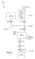
- FIG. 3 shows a packaging machine 202 with individual disposal and corresponds to large parts of the first packaging machine according to the embodiment according to Figure 1. Matching components are provided with reference numerals which are around the Value 200 are increased. In this regard, reference is made to the description in FIG.
- the embodiment according to FIG. 3 differs from that of FIG. 1 in that no vacuum central system 205 but a decentralized vacuum pump 245 is provided directly on the packaging machine 202.
- the vacuum pump 245 is connected via the vacuum supply line to the sealing chamber 204, wherein between the vacuum pump 245 and the chamber valve 206, a vacuum valve 241 is provided.
- a sensor 246 is provided which includes an oxygen probe 247 and a pressure transducer 248 includes.
- the sensor 246 corresponds to the sensors according to the Figures 1 and 2.
- a buffer volume 249 is provided in the form of a buffer chamber, the is connected via a buffer volume supply line 251 to the vacuum supply line 205 and between the chamber valve 206 and the vacuum valve 241 in the vacuum line 205 opens.
- a buffer valve 250 for shutting off the buffer volume lead 251 provided.
- a first Bottom film or a dish with the goods to be packaged and a top film in the opened seal chamber 204 introduced.
- the seal chamber 204 becomes airtight closed, wherein the chamber valve 206, the protective gas valve 212 and the Ventilation valve 213 are initially closed.
- the chamber valve 206 and the buffer valve 250 opened, the buffer volume 249 still has been evacuated from a previous procedure clock. It thus finds a pressure balance between the sealing chamber 204 and the buffer volume 249 instead.
- the buffer valve 250 is closed and the vacuum valve 241 is closed while the vacuum pump is running 245, so that the sealing chamber 204 by means of the vacuum pump 245 is further evacuated.
- the effluent from the sealing chamber 204 Gas is continuously analyzed with the sensor 246 to immediately increase the oxygen concentration to investigate.
- the pressure over time is in the form of an exponential function, i.
- the pressure drops quickly and further Evacuation progressively slower. Due to the initial pressure equalization between the buffer volume 249 and the sealing chamber 204 was thus initially ensures a rapid pressure drop, the buffer volume 249 that from the Seal chamber 204 caching escaping gas, without it to the vacuum pump 245 to promote.
- the buffer volume 249 that from the Seal chamber 204 caching escaping gas, without it to the vacuum pump 245 to promote.
- the further evacuation by means of the vacuum pump 245 already begins at a low pressure, so no major pressure fluctuations occur and a slow evacuation takes place.
- the pressure fluctuations are significantly lower than initially, so that the sensor 246 can continuously provide reliable values stop the vacuum pump 245 early enough or close the vacuum valve 241.
- the chamber valve 206 After evacuating the seal chamber 204, the chamber valve 206 is closed, whereupon the sealing chamber 204 as in the aforementioned embodiments filled with protective gas and then aerated. During that, that will be Check valve 250 is opened, so that the buffer volume 249 also by means of the vacuum pump 245 is evacuated with open vacuum valve 241. As the pressure in the Buffer volume 249 is also lower and the pressure in the seal chamber 204th after pressure equalization between the buffer volume 249 and the seal chamber 204 corresponds, also find no large pressure fluctuations during evacuation of the buffer volume 249 with the vacuum pump 245, so that the sensor 246 continuously provides reliable values to shut off the vacuum pump 245 early enough or to close the vacuum valve 241 soon enough Gas with excessive oxygen concentration reaches the vacuum pump 245. Thus, the buffer volume 249 is again sufficiently pre-evacuated to after the closing of the vacuum valve 241 again with the seal chamber 204 in the next Process cycle to be connected for pressure equalization.
Landscapes
- Chemical & Material Sciences (AREA)
- Dispersion Chemistry (AREA)
- Engineering & Computer Science (AREA)
- Mechanical Engineering (AREA)
- Vacuum Packaging (AREA)
- Physical Deposition Of Substances That Are Components Of Semiconductor Devices (AREA)
- Waste-Gas Treatment And Other Accessory Devices For Furnaces (AREA)
Abstract
Description
- Evakuieren eines Puffervolumens mittels einer Vakuumquelle,
- Verbinden des Puffervolumens mit der Kammer zur Erzielung eines Druckausgleichs zwischen dem Puffervolumen und der Kammer,
- Trennen des Puffervolumens von der Kammer,
- Ermitteln der Konzentration mindestens einer Gaskomponente des Schutzgases in der Atmosphäre des Puffervolumens oder
- Verbinden der Kammer mit der Vakuumquelle zum Evakuieren der Kammer und Ermitteln der Konzentration mindestens einer Gaskomponente des Schutzgases in der Atmosphäre des in dem während des Evakuierens aus der Kammer strömenden Gases,
ein Puffervolumen, das mit der Kammer verbindbar ist und derart gesteuert ist, dass das Puffervolumen vor dem Verbinden mit der Kammer evakuiert und daraufhin mit der Kammer zum Vorevakuieren derselben zeitweise verbunden ist,
eine Vakuumquelle, die zum Evakuieren der Kammer mit dieser verbindbar ist und derart gesteuert ist, dass sie nach dem Vorevakuieren der Kammer zeitweise mit dieser verbunden ist, sowie
ein Sensor zum Ermitteln der Konzentration mindestens einer Gaskomponente des Schutzgases in der Atmosphäre des Puffervolumens oder einer Zuleitung zur Vakuumquelle, gelöst.
ein Puffervolumen, das Bestandteil einer Vakuumquelle ist und das zum Evakuieren der Kammer mit dieser verbindbar ist und derart gesteuert ist, dass das Puffervolumen vor dem Verbinden mit der Kammer vorevakuiert und daraufhin mit der Kammer zeitweise verbunden ist,
ein Sensor zum Ermitteln der Konzentration mindestens einer Gaskomponente des Schutzgases in der Atmosphäre des Puffervolumens der Vakuumquelle der im Puffervolumen angeordnet ist, gelöst.
- Figur 1
- eine Skizze einer Vakuumzentralanlage, in der zweie Verpackungsmaschinen angeschlossen sind, mit einer in-situ Sauerstoffzentralüberwachung in ein Puffervolumen der Vakuumzentraleanlage;
- Figur 2
- eine Skizze einer Vakuumzentralanlage, der eine Verpackungsmaschine an geschlossen ist, mit einer Sauerstoffzentralüberwachung in einem Puffervolumen der Vakuumzentralanlage und einer extraktive Sauerststoffüberwachung an der Verpackungsmaschine und
- Figur 3
- eine Skizze einer Verpackungsmaschine mit Einzelentsorgung und einer extraktiven Sauerstoffüberwachung an der Verpackungsmaschine.
- Schritt 1:
- erstes Prüfkammerventil 139 wird geöffnet
Kammerventil 106 wird geöffnet
Gas aus Siegelkammer 104 strömt in Prüfkammer 136 (zeitgesteuert) - Schritt 2:
- erstes Prüfkammerventil 139 wird geschlossen
Verzögerungszeit läuft ab
Sauerstoffkonzentration in der Prüfkammer 136 wird gemessen - Schritt 3:
- Vakuumventil 141 wird geöffnet
Restgas aus Siegelkammer 104 wird durch Grobvakuumreservoir 114 entsorgt (druck- oder zeitgesteuert) - Schritt 4:
- Vakuumventil 141 wird geschlossen
Kammerventil 106 wird geschlossen
Verzögerungszeit läuft ab - Schritt 5:
- erstes Prüfkammerventil 139 wird geöffnet,
Schutzgasventil 112 wird geöffnet
Ende Sauerstoffkonzentrationsmessung
Schutzgas strömt in Siegelkammer 104 (druckgesteuert)
Druckanstieg nach erfolgtem Druckausgleich in Prüfkammer 136 bis zu den geschlossenen Ventilen zweites Prüfkammerventil 140, Vakuumventil 141 und Kammerventil 106 wird überwacht - Schritt 6:
- Schutzgasventil 112 wird geschlossen
Verzögerungszeit läuft ab - Schritt 7:
- erstes Prüfkammerventil 139 wird geschlossen
zweites Prüfkammerventil 140 wird geöffnet
Be-/Entlüftungsventil 113 wird geöffnet
Ende Druckanstiegsmessung
Prüfgas aus Prüfkammer 136 wird durch Grobvakuumreservoir 114 entsorgt
Druckausgleich der Siegelkammer 104 mit der Umgebung - Schritt 8:
- zweites Prüfkammerventil 140 wird geschlossen
Be-/Entlüftungsventil 113 wird geschlossen
Verzögerungszeit läuft ab
- Schritt 1:
- Vakuumventil 241 wird geöffnet
Gas aus Siegelkammer 204 strömt in Puffervolumen 249 (zeitgesteuert) - Schritt 2:
- Pufferventil 240 wird geschlossen
Verzögerungszeit läuft ab - Schritt 3:
- Vakuumventil 241 wird geöffnet
Restgas aus Siegelkammer 204 wird durch Vakuumpumpe 245 entsorgt (druck- oder zeitgesteuert)
Sauerstoffkonzentration wird gemessen - Schritt 4:
- Vakuumventil 241 wird geschlossen
Verzögerungszeit läuft ab - Schritt 5:
- Pufferventil 240 wird geöffnet
Schutzgasventil 212 wird geöffnet
Schutzgas strömt in Siegelkammer 204 (druckgesteuert) - Schritt 6:
- Schutzgasventil 212 wird geschlossen
Verzögerungszeit läuft ab - Schritt 7:
- Be-/Entlüftungsventil 213 wird geöffnet
Druckausgleich der Siegelkammer 204 mit der Umgebung - Schritt 8:
- Be-/Entlüftungsventil 213 wird geschlossen
Verzögerungszeit läuft ab
Ende Sauerstoffkonzentrationsmessung
- 1, 101
- Vakuumzentralanlage
- 2, 102, 202
- erste Verpackungsmaschine
- 3
- zweite Verpackungsmaschine
- 4, 104, 204
- Siegelkammer
- 5, 105, 205
- Vakuumzuleitung
- 6, 106, 206
- Kammerventil
- 7, 107, 207
- Druckmessumformer
- 8, 108, 208
- Schutzgaszuleitung
- 9, 109, 209
- Schutzgasquelle
- 10, 110, 210
- Druckbegrenzungsventil
- 11, 111,211
- Druckregelventil
- 12, 112,212
- Schutzgasventil
- 13, 113,213
- Be-/Entlüftungsventil
- 14, 114
- Grobvakuumreservoir
- 15, 115
- Feinvakuumreservoir
- 16, 116
- Vakuumpumpe
- 17, 117
- Vakuumpumpe
- 18, 118
- Schaltventil
- 19, 119
- Schaltventil
- 20, 120
- Verbindungsleitung
- 21, 121
- Vakuumpumpe
- 22, 122
- Vakuumpumpe
- 23, 123
- Schaltventil
- 24, 124
- Belüftungsventil
- 25, 125
- Belüftungsventil
- 26, 126
- erster Sensor
- 27, 127
- erste Sauerstoffsonde
- 28, 128
- erster Druckmessumformer
- 29, 129
- zweiter Sensor
- 30, 130
- zweite Sauerstoffsonde
- 31, 131
- zweiter Druckmessumformer
- 32
- erster Arm
- 33
- zweiter Arm
- 34
- erstes Vakuumventil
- 35
- zweites Vakuumventil
- 136
- Prüfkammer
- 137
- Prüfleitung
- 138
- Prüfkammerzuleitung
- 139
- erstes Prüfkammerventil
- 140
- zweites Prüfkammerventil
- 141,241
- Vakuumventil
- 142
- dritter Sensor
- 143
- dritte Sauerstoffsonde
- 144
- dritter Druckmessumformer
- 145
- vierter Druckmessumformer
- 245
- Vakuumpumpe
- 246
- Sensor
- 247
- Sauerstoffsonde
- 248
- Druckmessumwandler
- 249
- Puffervolumen
- 250
- Pufferventil
- 251
- Puffervolumenzuleitung
Claims (21)
- Verfahren zum Evakuieren einer mit Schutzgas befüllbaren Kammer (4, 104, 204), insbesondere einer Siegelkammer einer Verpackungsmaschine (2, 102, 202, 3, 103, 203), mit folgenden Verfahrensschritten:Evakuieren eines Puffervolumens (14, 15, 114, 115, 136, 249) mittels einer Vakuumquelle (1, 101, 245),Verbinden des Puffervolumens (14, 15, 114, 115, 136, 249) mit der Kammer (4, 104, 204) zur Erzielung eines Druckausgleichs zwischen dem Puffervolumen (14, 15, 114, 115, 136, 245) und der Kammer (4, 104, 204),Trennen des Puffervolumens (14, 15, 114, 115, 136, 249) von der Kammer (4, 104, 204),Ermitteln der Konzentration mindestens einer Gaskomponente des Schutzgases in der Atmosphäre des Puffervolumens (14, 15, 114, 115, 136) oderVerbinden der Kammer (204) mit der Vakuumquelle (245) zum Evakuieren der Kammer (204) und Ermitteln der Konzentration mindestens einer Gaskomponente des Schutzgases in der Atmosphäre des in dem während des Evakuierens aus der Kammer (204) strömenden Gases.
- Verfahren nach Anspruch 1,
dadurch gekennzeichnet, dass nach dem vollständigen Evakuieren der Kammer (4, 104, 204) diese mit Schutzgas befüllt wird. - Verfahren nach einem der Ansprüche 1 oder 2,
dadurch gekennzeichnet, dass die Kammer (104) zum Evakuieren mit der Vakuumquelle (101) während des Ermittelns der Konzentration mindestens einer Gaskomponente des Schutzgases in der Atmosphäre des Puffervolumens (136) zeitweise verbunden wird. - Verfahren nach einem der Ansprüche 1 bis 3,
dadurch gekennzeichnet, dass die Vakuumquelle ein Vakuumreservoir (114, 115) umfasst und
dass kontinuierlich die Konzentration mindestens einer Gaskomponente des Schutzgases in der Atmosphäre des Vakuumreservoirs (114, 115) ermittelt wird. - Verfahren nach einem der Ansprüche 1 bis 4,
dadurch gekennzeichnet, dass als Schutzgas ein Gas mit einer Sauerstoffkonzentration über der Sauerstoffkonzentration von Luft verwendet wird und
dass beim Ermitteln der Konzentration mindestens einer Gaskomponente des Schutzgases die Sauerstoffkonzentration ermittelt wird. - Verfahren nach Anspruch 5,
dadurch gekennzeichnet, dass bei Überschreiten einer vorbestimmten Sauerstoffkonzentration das Verfahren abgebrochen wird. - Verfahren nach Anspruch 6,
dadurch gekennzeichnet, dass die vorbestimmte Sauerstoffkonzentration über der Sauerstoffkonzentration von Luft liegt. - Verfahren nach einem der Ansprüche 1 oder 2,
dadurch gekennzeichnet, dass nach dem Evakuieren der Kammer (204) diese von der Vakuumquelle (245) getrennt wird und das Puffervolumen (249) zum Evakuieren mit der Vakuumquelle (245) verbunden wird und
dass die Konzentration mindestens einer Gaskomponente des Schutzgases in dem während des Evakuierens aus dem Puffervolumen (249) strömenden Gases ermittelt wird. - Vorrichtung zum Evakuieren einer mit Schutzgas befüllbaren Kammer (104, 204), insbesondere einer Siegelkammer einer Verpackungsmaschine (102, 202), umfassend
ein Puffervolumen (136, 249), das mit der Kammer (104, 204) verbindbar ist und derart gesteuert ist, dass das Puffervolumen (136, 249) vor dem Verbinden mit der Kammer (104, 204) evakuiert und daraufhin mit der Kammer (104, 204) zum Vorevakuieren derselben zeitweise verbunden ist,
eine Vakuumquelle (101, 245), die zum Evakuieren der Kammer (104, 204) mit dieser verbindbar ist und derart gesteuert ist, dass sie nach dem Vorevakuieren der Kammer (104, 204) zeitweise mit dieser verbunden ist, sowie
ein Sensor (142, 246) zum Ermitteln der Konzentration mindestens einer Gaskomponente des Schutzgases in der Atmosphäre des Puffervolumens (136) oder einer Zuleitung (205) zur Vakuumquelle (245). - Vorrichtung nach Anspruch 9,
dadurch gekennzeichnet, dass eine Schutzgasquelle (109, 209) vorgesehen ist, die mit der Kammer (104, 204) verbindbar ist und derart gesteuert ist, dass sie nach dem Evakuieren der Kammer (104, 204) mit dieser zeitweise verbunden ist. - Vorrichtung nach einem der Ansprüche 9 oder 10,
dadurch gekennzeichnet, dass der Sensor (142) im Puffervolumen (136) angeordnet ist und
dass eine vom Puffervolumen (136) separate Vakuumquelle (101) vorgesehen ist. - Vorrichtung nach Anspruch 11,
dadurch gekennzeichnet, dass die Vakuumquelle (101) zumindest ein Vakuumreservoir (114, 115) umfasst. - Vorrichtung nach Anspruch 12,
dadurch gekennzeichnet, dass in dem Vakuumreservoir (114, 115) ein weiterer Sensor (126, 129) zum Ermitteln der Konzentration mindestens einer Gaskomponente des Schutzgases in der Atmosphäre des Vakuumreservoirs (114, 115) angeordnet ist. - Vorrichtung nach einem der Ansprüche 9 bis 13,
dadurch gekennzeichnet, dass eine Vakuumzuleitung (105) zum Verbinden Kammer (104) mit der Vakuumquelle (101) vorgesehen ist,
dass ein Vakuumventil (141) in der Vakuumzuleitung (105) zum Absperren derselben vorgesehen ist,
dass eine Prüfkammer (136) vorgesehen ist, die das Puffervolumen darstellt und die über eine Prüfleitung (137) mit der Vakuumzuleitung (105) verbindbar ist, wobei die Prüfleitung (137) zwischen dem Vakuumventil (141) und dem Kammerventil (106) in die Vakuumzuleitung (105) mündet,
dass ein Sensor (142) zur Ermittelung der Konzentration mindestens einer Gaskomponente des Schutzgases in der Atmosphäre der Prüfkammer (136) vorgesehen ist,
dass ein Prüfkammerventil (139) in der Prüfleitung (137) zum Absperren derselben vorgesehen ist und
dass ein Schutzgasventil (112) in der Schutzgaszuleitung (108) zum Absperren derselben und eine Steuerung zum Steuern der Ventil vorgesehen ist. - Vorrichtung nach Anspruch 14,
dadurch gekennzeichnet, dass ein Kammerventil (106) in der Vakuumzuleitung (105) zwischen dem Vakuumventil (141) und der Kammer (104) zum Absperren der Vakuumzuleitung (105) vorgesehen ist. - Vorrichtung nach einem der Ansprüche 14 oder 15,
dadurch gekennzeichnet, dass die Schutzgasquelle (109) über eine Schutzgaszuleitung (108) mit der Kammer (104) verbindbar ist. - Vorrichtung nach einem der Ansprüche 14 bis 16,
dadurch gekennzeichnet, dass die Prüfkammer (136) über eine Prüfkammerzuleitung (138) mit der Vakuumzuleitung (105) verbindbar ist, wobei die Prüfkammerzuleitung (138) zwischen dem Vakuumventil (141) und der Vakuumquelle (101) in die Vakuumzuleitung (105) mündet, und
dass in der Prüfkammerzuleitung (138) ein zweites Prüfkammerventil (140) zum Absperren der Prüfkammerzuleitung (138) vorgesehen ist. - Vorrichtung nach einem der Ansprüche 9 oder 10,
dadurch gekennzeichnet, dass der Sensor (246) in einer Zuleitung (205) zur Vakuumquelle, die in Form einer Vakuumpumpe (245) dargestellt ist, vorgesehen ist. - Vorrichtung zum Evakuieren einer mit Schutzgas befüllbaren Kammer (104, 204), insbesondere einer Siegelkammer einer Verpackungsmaschine (102, 202), umfassend
ein Puffervolumen (14, 15), das Bestandteil einer Vakuumquelle (1) ist und das zum Evakuieren der Kammer (4) mit dieser verbindbar ist und derart gesteuert ist, dass das Puffervolumen (14, 15) vor dem Verbinden mit der Kammer (4) vorevakuiert und daraufhin mit der Kammer (4) zeitweise verbunden ist,
ein Sensor (26, 29) zum Ermitteln der Konzentration mindestens einer Gaskomponente des Schutzgases in der Atmosphäre des Puffervolumens (14, 15) der Vakuumquelle (1) der im Puffervolumen (14, 15) angeordnet ist. - Vorrichtung nach Anspruch 19,
dadurch gekennzeichnet, dass eine Schutzgasquelle (9) vorgesehen ist, die mit der Kammer (4) verbindbar ist und derart gesteuert ist, dass sie nach dem Evakuieren der Kammer (4) mit dieser zeitweise verbunden ist. - Vorrichtung nach einem der Ansprüche 9 bis 20,
dadurch gekennzeichnet, dass der Sensor (26, 29, 126, 129, 142, 246) zum Ermitteln der Konzentration mindestens einer Gaskomponente des Schutzgases in der Atmosphäre eine Sauerstoffsonde (27, 30, 127, 130, 143, 247) umfasst.
Applications Claiming Priority (2)
| Application Number | Priority Date | Filing Date | Title |
|---|---|---|---|
| DE102004024480A DE102004024480A1 (de) | 2004-05-14 | 2004-05-14 | Verfahren und Vorrichtung zum Evakuieren einer Kammer |
| DE102004024480 | 2004-05-14 |
Publications (2)
| Publication Number | Publication Date |
|---|---|
| EP1595794A1 true EP1595794A1 (de) | 2005-11-16 |
| EP1595794B1 EP1595794B1 (de) | 2008-10-08 |
Family
ID=34935797
Family Applications (1)
| Application Number | Title | Priority Date | Filing Date |
|---|---|---|---|
| EP05009182A Expired - Lifetime EP1595794B1 (de) | 2004-05-14 | 2005-04-27 | Verfahren und Vorrichtung zum Evakuieren einer Kammer |
Country Status (4)
| Country | Link |
|---|---|
| EP (1) | EP1595794B1 (de) |
| AT (1) | ATE410364T1 (de) |
| DE (2) | DE102004024480A1 (de) |
| DK (1) | DK1595794T3 (de) |
Cited By (8)
| Publication number | Priority date | Publication date | Assignee | Title |
|---|---|---|---|---|
| WO2013026522A1 (de) * | 2011-08-25 | 2013-02-28 | Khs Gmbh | Vakuumeinrichtung für anlangen zur behandlung von behälten sowie verfahren zur steuerung einer vakuumeinrichtung |
| EP2586315A2 (de) | 2011-10-29 | 2013-05-01 | Messer Austria GmbH | Schutzgas zum Verpacken von Fleisch- und Wurstwaren |
| WO2014173802A1 (de) * | 2013-04-24 | 2014-10-30 | Gea Food Solutions Germany Gmbh | Werkzeugintegriertes ventil für grob- und/oder feinvakuum |
| WO2017102541A1 (de) * | 2015-12-14 | 2017-06-22 | Gea Food Solutions Germany Gmbh | Verpackungsmaschine und verfahren zur herstellung von vakuumierten verpackungen |
| EP3560845A1 (de) * | 2018-04-27 | 2019-10-30 | MULTIVAC Sepp Haggenmüller SE & Co. KG | Verpackungsmaschine und verfahren zum verpacken von produkten in kunststoffverpackungen |
| US11111040B2 (en) * | 2018-01-08 | 2021-09-07 | Multivac Sepp Haggenmueller Se & Co. Kg | Packaging machine with pressure control device and method |
| CN115041070A (zh) * | 2022-05-27 | 2022-09-13 | 中材锂膜有限公司 | 一种用于物料生产的密闭式气体平衡系统 |
| CN115847992A (zh) * | 2022-12-20 | 2023-03-28 | 宁波甬强科技有限公司 | 层压机真空回收利用系统及方法 |
Families Citing this family (1)
| Publication number | Priority date | Publication date | Assignee | Title |
|---|---|---|---|---|
| DE102010055438A1 (de) * | 2010-12-21 | 2012-06-21 | Multivac Sepp Haggenmüller Gmbh & Co. Kg | Verpackungsmaschine und Verfahren zum Erzeugen einer Vakuumverpackung |
Citations (4)
| Publication number | Priority date | Publication date | Assignee | Title |
|---|---|---|---|---|
| DE2829889A1 (de) * | 1978-07-07 | 1980-01-24 | Leybold Heraeus Gmbh & Co Kg | Verfahren und vorrichtung zur wiederholten evakuierung abgeschlossener volumina |
| EP0622301A1 (de) * | 1993-04-29 | 1994-11-02 | Rudolf Christoph Bilz | Evakuiervorrichtung |
| EP0721888A1 (de) * | 1995-01-12 | 1996-07-17 | Bilz, Rudolf Christoph | Anlage zur Druckabsenkung in den Arbeitskammern mehrerer an eine Vakuumzentralanlage angeschlossener Verbraucher |
| US5822951A (en) * | 1997-11-06 | 1998-10-20 | Modern Controls, Inc. | Apparatus and method for sampling gas in product packages |
Family Cites Families (1)
| Publication number | Priority date | Publication date | Assignee | Title |
|---|---|---|---|---|
| DE3411917A1 (de) * | 1984-03-30 | 1985-10-03 | Multivac Sepp Haggenmüller KG, 8941 Wolfertschwenden | Verfahren und vorrichtung zum verpacken von gegenstaenden |
-
2004
- 2004-05-14 DE DE102004024480A patent/DE102004024480A1/de not_active Withdrawn
-
2005
- 2005-04-27 DE DE502005005582T patent/DE502005005582D1/de not_active Expired - Lifetime
- 2005-04-27 AT AT05009182T patent/ATE410364T1/de not_active IP Right Cessation
- 2005-04-27 EP EP05009182A patent/EP1595794B1/de not_active Expired - Lifetime
- 2005-04-27 DK DK05009182T patent/DK1595794T3/da active
Patent Citations (4)
| Publication number | Priority date | Publication date | Assignee | Title |
|---|---|---|---|---|
| DE2829889A1 (de) * | 1978-07-07 | 1980-01-24 | Leybold Heraeus Gmbh & Co Kg | Verfahren und vorrichtung zur wiederholten evakuierung abgeschlossener volumina |
| EP0622301A1 (de) * | 1993-04-29 | 1994-11-02 | Rudolf Christoph Bilz | Evakuiervorrichtung |
| EP0721888A1 (de) * | 1995-01-12 | 1996-07-17 | Bilz, Rudolf Christoph | Anlage zur Druckabsenkung in den Arbeitskammern mehrerer an eine Vakuumzentralanlage angeschlossener Verbraucher |
| US5822951A (en) * | 1997-11-06 | 1998-10-20 | Modern Controls, Inc. | Apparatus and method for sampling gas in product packages |
Cited By (17)
| Publication number | Priority date | Publication date | Assignee | Title |
|---|---|---|---|---|
| US9599104B2 (en) | 2011-08-25 | 2017-03-21 | Khs Gmbh | Vacuum device for plants for the processing of containers, and method for controlling a vacuum device |
| WO2013026522A1 (de) * | 2011-08-25 | 2013-02-28 | Khs Gmbh | Vakuumeinrichtung für anlangen zur behandlung von behälten sowie verfahren zur steuerung einer vakuumeinrichtung |
| EP2748104B1 (de) | 2011-08-25 | 2015-09-30 | KHS GmbH | Vakuumeinrichtung für anlagen zur behandlung von behältern sowie verfahren zur steuerung einer vakuumeinrichtung |
| EP2586315A2 (de) | 2011-10-29 | 2013-05-01 | Messer Austria GmbH | Schutzgas zum Verpacken von Fleisch- und Wurstwaren |
| DE102011122769A1 (de) | 2011-10-29 | 2013-05-02 | Messer Austria Gmbh | Schutzgas zum Verpacken von Fleisch- und Wurstwaren |
| RU2661383C2 (ru) * | 2013-04-24 | 2018-07-16 | Геа Фуд Сольюшнс Джемени Гмбх | Упаковочная машина, содержащая встроенный в инструмент клапан для низкого и/или среднего вакуума |
| CN105189293A (zh) * | 2013-04-24 | 2015-12-23 | Gea食品策划德国股份有限公司 | 用于低真空和/或高真空的工具集成阀 |
| WO2014173802A1 (de) * | 2013-04-24 | 2014-10-30 | Gea Food Solutions Germany Gmbh | Werkzeugintegriertes ventil für grob- und/oder feinvakuum |
| EP3459866A3 (de) * | 2013-04-24 | 2019-06-26 | GEA Food Solutions Germany GmbH | Verfahren zum evakuieren einer kammer |
| WO2017102541A1 (de) * | 2015-12-14 | 2017-06-22 | Gea Food Solutions Germany Gmbh | Verpackungsmaschine und verfahren zur herstellung von vakuumierten verpackungen |
| US11111040B2 (en) * | 2018-01-08 | 2021-09-07 | Multivac Sepp Haggenmueller Se & Co. Kg | Packaging machine with pressure control device and method |
| EP3560845A1 (de) * | 2018-04-27 | 2019-10-30 | MULTIVAC Sepp Haggenmüller SE & Co. KG | Verpackungsmaschine und verfahren zum verpacken von produkten in kunststoffverpackungen |
| CN110406721A (zh) * | 2018-04-27 | 2019-11-05 | 莫迪维克西普哈根牧勒股份及两合公司 | 用于将产品包装在塑料包装中的包装机 |
| CN110406721B (zh) * | 2018-04-27 | 2021-04-09 | 莫迪维克西普哈根牧勒股份及两合公司 | 用于将产品包装在塑料包装中的包装机 |
| US11040795B2 (en) | 2018-04-27 | 2021-06-22 | Multivac Sepp Haggenmueller Se & Co. Kg | Packaging machine for packaging products in plastic packaging |
| CN115041070A (zh) * | 2022-05-27 | 2022-09-13 | 中材锂膜有限公司 | 一种用于物料生产的密闭式气体平衡系统 |
| CN115847992A (zh) * | 2022-12-20 | 2023-03-28 | 宁波甬强科技有限公司 | 层压机真空回收利用系统及方法 |
Also Published As
| Publication number | Publication date |
|---|---|
| EP1595794B1 (de) | 2008-10-08 |
| ATE410364T1 (de) | 2008-10-15 |
| DE102004024480A1 (de) | 2005-12-08 |
| DE502005005582D1 (de) | 2008-11-20 |
| DK1595794T3 (da) | 2009-04-14 |
Similar Documents
| Publication | Publication Date | Title |
|---|---|---|
| DE69726271T2 (de) | Verfahren zur bearbeitung eines produktes und installation zur leckaufspürung | |
| EP0789235B1 (de) | Prüfung von Behältnissen | |
| EP2994736B1 (de) | Dichtheitsprüfanordnung und dichtheitsprüfverfahren | |
| WO2002095369A1 (de) | Verfahren und vorrichtung zum bestimmen der permeation einer barriereschicht | |
| EP1595794B1 (de) | Verfahren und Vorrichtung zum Evakuieren einer Kammer | |
| EP0593748B1 (de) | Verfahren zum verpacken von gut unter vakuum und vakuum-verpackungsmaschine | |
| EP3795532B1 (de) | Verfahren und vorrichtung zum befüllen eines behälters mit einem füllprodukt | |
| DE69406381T2 (de) | Verfahren und Anlage zum Verpacken von Kaffee | |
| DE69623171T2 (de) | Leckprüfverfahren und -vorrichtung für mindestens eine flexibele Verpackung | |
| EP3227655A1 (de) | Dichtheitsprüfung mit trägergas in folienkammer | |
| DE3889164T2 (de) | Verfahren zur herstellung eines hermetisch geschlossenen behälters. | |
| DE3936163C2 (de) | ||
| DE69611080T2 (de) | Vorrichtung und Verfahren zum Entfernen von Sauerstoff aus Lebensmittelverpackungen | |
| EP3587285B1 (de) | Verfahren zur volumenstrom- und füllgradbestimmung an einer verpackungsmaschine | |
| DE19942185A1 (de) | Verfahren und Vorrichtung zur Ermittlung von Leckage- oder Nutzvolumen- oder -massenströmen | |
| EP2914944B1 (de) | Verfahren zur prüfung einer dichtheitsprüfanlage | |
| EP0368839B1 (de) | Verfahren zum Aufbewahren von biologischen Substanzen, sowie Einrichtung zur Durchführung dieses Verfahrens | |
| DE3340353C2 (de) | ||
| DE4243327A1 (de) | Vorrichtung zum pneumatischen Fördern von Schüttgut | |
| DE102013104682B3 (de) | Dichtheitsprüfanordnung und Dichtheitsprüfverfahren | |
| EP3560845B1 (de) | Verpackungsmaschine und verfahren zum verpacken von produkten in kunststoffverpackungen | |
| DE3439778A1 (de) | Vorrichtung und verfahren zur entnahme von gas aus dosen o.dgl. packungen | |
| DE2441123A1 (de) | Verfahren zur dichtigkeitspruefung von gegenstaenden | |
| DE2428399A1 (de) | Verfahren und vorrichtung zum zerstoerungsfreien festigkeitspruefen von gasdurchlaessigen gegenstaenden wie z.b. zigaretten | |
| DE69809935T2 (de) | VERFAHREN UND EINRICHTUNG ZUr KONSERVIERUnG VON NAHRUNGSMITTELN |
Legal Events
| Date | Code | Title | Description |
|---|---|---|---|
| PUAI | Public reference made under article 153(3) epc to a published international application that has entered the european phase |
Free format text: ORIGINAL CODE: 0009012 |
|
| AK | Designated contracting states |
Kind code of ref document: A1 Designated state(s): AT BE BG CH CY CZ DE DK EE ES FI FR GB GR HU IE IS IT LI LT LU MC NL PL PT RO SE SI SK TR |
|
| AX | Request for extension of the european patent |
Extension state: AL BA HR LV MK YU |
|
| RAP1 | Party data changed (applicant data changed or rights of an application transferred) |
Owner name: BIS VAKUUMTECHNIK GMBH |
|
| RIN1 | Information on inventor provided before grant (corrected) |
Inventor name: FELIX RUDOLF BILZ Inventor name: SASCHA BILZ |
|
| RIN1 | Information on inventor provided before grant (corrected) |
Inventor name: BILZ SASCHA Inventor name: BILZ, FELIX RUDOLF |
|
| 17P | Request for examination filed |
Effective date: 20060407 |
|
| RIN1 | Information on inventor provided before grant (corrected) |
Inventor name: BILZ, FELIX RUDOLF Inventor name: BILZ, SASCHA |
|
| RIN1 | Information on inventor provided before grant (corrected) |
Inventor name: BILZ, FELIX RUDOLF Inventor name: BILZ, SASCHA |
|
| AKX | Designation fees paid |
Designated state(s): AT BE BG CH CY CZ DE DK EE ES FI FR GB GR HU IE IS IT LI LT LU MC NL PL PT RO SE SI SK TR |
|
| 17Q | First examination report despatched |
Effective date: 20070611 |
|
| GRAP | Despatch of communication of intention to grant a patent |
Free format text: ORIGINAL CODE: EPIDOSNIGR1 |
|
| GRAS | Grant fee paid |
Free format text: ORIGINAL CODE: EPIDOSNIGR3 |
|
| GRAA | (expected) grant |
Free format text: ORIGINAL CODE: 0009210 |
|
| AK | Designated contracting states |
Kind code of ref document: B1 Designated state(s): AT BE BG CH CY CZ DE DK EE ES FI FR GB GR HU IE IS IT LI LT LU MC NL PL PT RO SE SI SK TR |
|
| REG | Reference to a national code |
Ref country code: GB Ref legal event code: FG4D Free format text: NOT ENGLISH |
|
| REG | Reference to a national code |
Ref country code: CH Ref legal event code: EP |
|
| REG | Reference to a national code |
Ref country code: IE Ref legal event code: FG4D Free format text: LANGUAGE OF EP DOCUMENT: GERMAN |
|
| REF | Corresponds to: |
Ref document number: 502005005582 Country of ref document: DE Date of ref document: 20081120 Kind code of ref document: P |
|
| PG25 | Lapsed in a contracting state [announced via postgrant information from national office to epo] |
Ref country code: SI Free format text: LAPSE BECAUSE OF FAILURE TO SUBMIT A TRANSLATION OF THE DESCRIPTION OR TO PAY THE FEE WITHIN THE PRESCRIBED TIME-LIMIT Effective date: 20081008 |
|
| REG | Reference to a national code |
Ref country code: DK Ref legal event code: T3 |
|
| PG25 | Lapsed in a contracting state [announced via postgrant information from national office to epo] |
Ref country code: LT Free format text: LAPSE BECAUSE OF FAILURE TO SUBMIT A TRANSLATION OF THE DESCRIPTION OR TO PAY THE FEE WITHIN THE PRESCRIBED TIME-LIMIT Effective date: 20081008 Ref country code: ES Free format text: LAPSE BECAUSE OF FAILURE TO SUBMIT A TRANSLATION OF THE DESCRIPTION OR TO PAY THE FEE WITHIN THE PRESCRIBED TIME-LIMIT Effective date: 20090119 Ref country code: BG Free format text: LAPSE BECAUSE OF FAILURE TO SUBMIT A TRANSLATION OF THE DESCRIPTION OR TO PAY THE FEE WITHIN THE PRESCRIBED TIME-LIMIT Effective date: 20090108 |
|
| PG25 | Lapsed in a contracting state [announced via postgrant information from national office to epo] |
Ref country code: IS Free format text: LAPSE BECAUSE OF FAILURE TO SUBMIT A TRANSLATION OF THE DESCRIPTION OR TO PAY THE FEE WITHIN THE PRESCRIBED TIME-LIMIT Effective date: 20090208 Ref country code: PL Free format text: LAPSE BECAUSE OF FAILURE TO SUBMIT A TRANSLATION OF THE DESCRIPTION OR TO PAY THE FEE WITHIN THE PRESCRIBED TIME-LIMIT Effective date: 20081008 Ref country code: PT Free format text: LAPSE BECAUSE OF FAILURE TO SUBMIT A TRANSLATION OF THE DESCRIPTION OR TO PAY THE FEE WITHIN THE PRESCRIBED TIME-LIMIT Effective date: 20090218 Ref country code: FI Free format text: LAPSE BECAUSE OF FAILURE TO SUBMIT A TRANSLATION OF THE DESCRIPTION OR TO PAY THE FEE WITHIN THE PRESCRIBED TIME-LIMIT Effective date: 20081008 |
|
| REG | Reference to a national code |
Ref country code: IE Ref legal event code: FD4D |
|
| PG25 | Lapsed in a contracting state [announced via postgrant information from national office to epo] |
Ref country code: RO Free format text: LAPSE BECAUSE OF FAILURE TO SUBMIT A TRANSLATION OF THE DESCRIPTION OR TO PAY THE FEE WITHIN THE PRESCRIBED TIME-LIMIT Effective date: 20081008 Ref country code: IE Free format text: LAPSE BECAUSE OF FAILURE TO SUBMIT A TRANSLATION OF THE DESCRIPTION OR TO PAY THE FEE WITHIN THE PRESCRIBED TIME-LIMIT Effective date: 20081008 Ref country code: EE Free format text: LAPSE BECAUSE OF FAILURE TO SUBMIT A TRANSLATION OF THE DESCRIPTION OR TO PAY THE FEE WITHIN THE PRESCRIBED TIME-LIMIT Effective date: 20081008 |
|
| PLBE | No opposition filed within time limit |
Free format text: ORIGINAL CODE: 0009261 |
|
| STAA | Information on the status of an ep patent application or granted ep patent |
Free format text: STATUS: NO OPPOSITION FILED WITHIN TIME LIMIT |
|
| PG25 | Lapsed in a contracting state [announced via postgrant information from national office to epo] |
Ref country code: SE Free format text: LAPSE BECAUSE OF FAILURE TO SUBMIT A TRANSLATION OF THE DESCRIPTION OR TO PAY THE FEE WITHIN THE PRESCRIBED TIME-LIMIT Effective date: 20090108 Ref country code: IT Free format text: LAPSE BECAUSE OF FAILURE TO SUBMIT A TRANSLATION OF THE DESCRIPTION OR TO PAY THE FEE WITHIN THE PRESCRIBED TIME-LIMIT Effective date: 20081008 Ref country code: CZ Free format text: LAPSE BECAUSE OF FAILURE TO SUBMIT A TRANSLATION OF THE DESCRIPTION OR TO PAY THE FEE WITHIN THE PRESCRIBED TIME-LIMIT Effective date: 20081008 |
|
| 26N | No opposition filed |
Effective date: 20090709 |
|
| PG25 | Lapsed in a contracting state [announced via postgrant information from national office to epo] |
Ref country code: SK Free format text: LAPSE BECAUSE OF FAILURE TO SUBMIT A TRANSLATION OF THE DESCRIPTION OR TO PAY THE FEE WITHIN THE PRESCRIBED TIME-LIMIT Effective date: 20081008 |
|
| BERE | Be: lapsed |
Owner name: BIS VAKUUMTECHNIK G.M.B.H. Effective date: 20090430 |
|
| REG | Reference to a national code |
Ref country code: CH Ref legal event code: PL |
|
| GBPC | Gb: european patent ceased through non-payment of renewal fee |
Effective date: 20090427 |
|
| NLV4 | Nl: lapsed or anulled due to non-payment of the annual fee |
Effective date: 20091101 |
|
| REG | Reference to a national code |
Ref country code: FR Ref legal event code: ST Effective date: 20091231 |
|
| PG25 | Lapsed in a contracting state [announced via postgrant information from national office to epo] |
Ref country code: LI Free format text: LAPSE BECAUSE OF NON-PAYMENT OF DUE FEES Effective date: 20090430 Ref country code: CH Free format text: LAPSE BECAUSE OF NON-PAYMENT OF DUE FEES Effective date: 20090430 |
|
| PG25 | Lapsed in a contracting state [announced via postgrant information from national office to epo] |
Ref country code: NL Free format text: LAPSE BECAUSE OF NON-PAYMENT OF DUE FEES Effective date: 20091101 |
|
| PG25 | Lapsed in a contracting state [announced via postgrant information from national office to epo] |
Ref country code: FR Free format text: LAPSE BECAUSE OF NON-PAYMENT OF DUE FEES Effective date: 20091222 Ref country code: GB Free format text: LAPSE BECAUSE OF NON-PAYMENT OF DUE FEES Effective date: 20090427 Ref country code: MC Free format text: LAPSE BECAUSE OF NON-PAYMENT OF DUE FEES Effective date: 20090430 |
|
| PG25 | Lapsed in a contracting state [announced via postgrant information from national office to epo] |
Ref country code: BE Free format text: LAPSE BECAUSE OF NON-PAYMENT OF DUE FEES Effective date: 20090430 |
|
| PG25 | Lapsed in a contracting state [announced via postgrant information from national office to epo] |
Ref country code: AT Free format text: LAPSE BECAUSE OF NON-PAYMENT OF DUE FEES Effective date: 20090427 |
|
| PG25 | Lapsed in a contracting state [announced via postgrant information from national office to epo] |
Ref country code: GR Free format text: LAPSE BECAUSE OF FAILURE TO SUBMIT A TRANSLATION OF THE DESCRIPTION OR TO PAY THE FEE WITHIN THE PRESCRIBED TIME-LIMIT Effective date: 20090109 |
|
| PGFP | Annual fee paid to national office [announced via postgrant information from national office to epo] |
Ref country code: DE Payment date: 20100623 Year of fee payment: 6 |
|
| REG | Reference to a national code |
Ref country code: DK Ref legal event code: EBP |
|
| PG25 | Lapsed in a contracting state [announced via postgrant information from national office to epo] |
Ref country code: LU Free format text: LAPSE BECAUSE OF NON-PAYMENT OF DUE FEES Effective date: 20090427 Ref country code: DK Free format text: LAPSE BECAUSE OF NON-PAYMENT OF DUE FEES Effective date: 20100503 |
|
| PG25 | Lapsed in a contracting state [announced via postgrant information from national office to epo] |
Ref country code: DK Free format text: LAPSE BECAUSE OF NON-PAYMENT OF DUE FEES Effective date: 20090430 |
|
| PG25 | Lapsed in a contracting state [announced via postgrant information from national office to epo] |
Ref country code: HU Free format text: LAPSE BECAUSE OF FAILURE TO SUBMIT A TRANSLATION OF THE DESCRIPTION OR TO PAY THE FEE WITHIN THE PRESCRIBED TIME-LIMIT Effective date: 20090409 |
|
| PG25 | Lapsed in a contracting state [announced via postgrant information from national office to epo] |
Ref country code: TR Free format text: LAPSE BECAUSE OF FAILURE TO SUBMIT A TRANSLATION OF THE DESCRIPTION OR TO PAY THE FEE WITHIN THE PRESCRIBED TIME-LIMIT Effective date: 20081008 |
|
| PG25 | Lapsed in a contracting state [announced via postgrant information from national office to epo] |
Ref country code: CY Free format text: LAPSE BECAUSE OF FAILURE TO SUBMIT A TRANSLATION OF THE DESCRIPTION OR TO PAY THE FEE WITHIN THE PRESCRIBED TIME-LIMIT Effective date: 20081008 |
|
| PG25 | Lapsed in a contracting state [announced via postgrant information from national office to epo] |
Ref country code: DE Free format text: LAPSE BECAUSE OF NON-PAYMENT OF DUE FEES Effective date: 20111101 |
|
| REG | Reference to a national code |
Ref country code: DE Ref legal event code: R119 Ref document number: 502005005582 Country of ref document: DE Effective date: 20111101 |