EP1596006A1 - Poutre égaliseuse extensible - Google Patents
Poutre égaliseuse extensible Download PDFInfo
- Publication number
- EP1596006A1 EP1596006A1 EP04011028A EP04011028A EP1596006A1 EP 1596006 A1 EP1596006 A1 EP 1596006A1 EP 04011028 A EP04011028 A EP 04011028A EP 04011028 A EP04011028 A EP 04011028A EP 1596006 A1 EP1596006 A1 EP 1596006A1
- Authority
- EP
- European Patent Office
- Prior art keywords
- screed
- end wall
- variable length
- paving machine
- set forth
- Prior art date
- Legal status (The legal status is an assumption and is not a legal conclusion. Google has not performed a legal analysis and makes no representation as to the accuracy of the status listed.)
- Granted
Links
Images





Classifications
-
- E—FIXED CONSTRUCTIONS
- E01—CONSTRUCTION OF ROADS, RAILWAYS, OR BRIDGES
- E01C—CONSTRUCTION OF, OR SURFACES FOR, ROADS, SPORTS GROUNDS, OR THE LIKE; MACHINES OR AUXILIARY TOOLS FOR CONSTRUCTION OR REPAIR
- E01C19/00—Machines, tools or auxiliary devices for preparing or distributing paving materials, for working the placed materials, or for forming, consolidating, or finishing the paving
- E01C19/22—Machines, tools or auxiliary devices for preparing or distributing paving materials, for working the placed materials, or for forming, consolidating, or finishing the paving for consolidating or finishing laid-down unset materials
- E01C19/42—Machines for imparting a smooth finish to freshly-laid paving courses other than by rolling, tamping or vibrating
-
- E—FIXED CONSTRUCTIONS
- E01—CONSTRUCTION OF ROADS, RAILWAYS, OR BRIDGES
- E01C—CONSTRUCTION OF, OR SURFACES FOR, ROADS, SPORTS GROUNDS, OR THE LIKE; MACHINES OR AUXILIARY TOOLS FOR CONSTRUCTION OR REPAIR
- E01C2301/00—Machine characteristics, parts or accessories not otherwise provided for
- E01C2301/14—Extendable screeds
- E01C2301/16—Laterally slidable screeds
Definitions
- the present invention relates to paving machines having screed assemblies and, more particularly, to screed assemblies having linearly extendable portions.
- Paving machines are used for depositing, spreading, compacting, and smoothing paving material on a roadbed in such a manner that a uniform and drivable surface is produced.
- Screed assemblies are used to smooth and compact the paving material.
- the screed assembly is typically drawn behind the paving machine and is adjustable to establish both the thickness of the deposited layer of paving material and the width of the area over which the material is spread.
- Modem screed assemblies typically include one or more base or fixed portions and one or more extendable portions that may be adjusted relative to the fixed portions to control the working width of the screed assembly.
- a common arrangement uses two base portions arranged end to end such that they may be independently tipped from horizontal to permit laying a paved mat having a desired cross-section, for example, a center crown.
- Each base portion commonly includes an extendable portion that may be moved inwardly to minimize the width of the screed assembly during transport and may be extended outwardly up to a maximum extended length to increase the paving capacity of the machine.
- the fully extended screed width is at least twice the fully retracted width.
- achieving a full doubling of screed width is difficult because of necessary structural overlaps in portions of the fixed and extendable screed elements. Because of this, the fully extended screed width is typically several centimeters less than double the fully retracted width.
- the present invention is directed to providing a double extending screed that overcomes one or more of the problems set forth above.
- a screed assembly for a paving machine includes a main screed portion having a fixed length frame and an extension screed portion having a variable length frame defined by an inner end wall and an outer end wall and having an intermediate wall.
- the inner end wall and intermediate walls are axially movable one relative to the other.
- a coupling portion is located between the inner and outer end walls and has a first coupling member connected to the inner end wall and extending through the intermediate wall toward the outer end wall and a second coupling member connected to the outer end wall and extending to the intermediate wall.
- the coupling members are coaxially slidable one within the other.
- An actuator is adapted to controllably move the extension screed portion longitudinally axially relative to the main screed portion between a fully retracted position at which the intermediate wall is urged toward the inner end wall and a fully extended position at which the intermediate wall is urged away from the inner end wall.
- a method for providing an extendable screed assembly for a paving machine.
- the screed assembly has a main screed portion having a fixed length frame and an extension screed portion extendable from the main screed portion.
- the extension screed portion has a variable length frame defined by an inner end wall and an outer end wall and has an intermediate wall.
- the inner end wall and intermediate walls are axially movable one relative to the other.
- a coupling portion is located between the inner and outer end walls and has a first coupling member connected to the inner end wall and extending through the intermediate wall to the outer end wall and a second coupling member connected to the outer end wall and extending to the intermediate wall.
- the first and second coupling members are coaxially slidable one within the other.
- An actuator is adapted to controllably move the extension screed portion longitudinally axially relative to the main screed portion between a fully retracted and a fully extended position.
- the method includes the steps of moving the variable length portion intermediate wall toward the inner end wall in response to the actuator moving the extension screed portion to the fully retracted position and moving the variable length portion intermediate wall away from the inner end wall in response to the actuator moving the extension screed portion to the fully extended position.
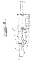
- a paving machine (not shown) has a screed assembly 10.
- the screed assembly 10 may be connected to the paving machine via drawbars or in other conventional manners known in the art.
- the screed assembly 10 includes an elongate main screed portion 14 having a fixed length frame 18, and an elongate extension screed portion 22 longitudinally axially extendable from the main screed portion 14.
- the extension screed portion 22 has a variable length frame 26 partially defined by an inner end wall 30 and an outer end wall 34 and including an intermediate wall 38. The inner end wall 30 and the intermediate wall 38 are axially movable one relative to the other.
- a coupling portion 42 is located between the variable length frame inner and outer end walls 30, 34.
- the coupling portion 42 has a first coupling member 46 connected to the inner end wall 30 and extending through the intermediate wall 38 toward the outer end wall 34, and a second coupling member 50 connected to the outer end wall 34 and extending to the intermediate wall 38.
- the first and second coupling members 46, 50 are coaxially slidable one within the other, and in a preferred embodiment cooperate to form an elongated cavity.
- the first and second coupling members 46, 50 are coaxially positioned cylinders 48, 52, one slidable within the other.
- the coupling members 46, 50 could be constructed of other configurations suitable for coaxial interaction such as triangular, rectangular, or other curved or polygonal structures.
- An actuator 54 has a first end portion 58 connected to the main screed portion frame 18 and a second end portion 62 connected to the extension screed portion variable length frame outer end wall 34.
- the actuator 54 may be a linear operator such as a hydraulic cylinder, and may be at least partially located within the elongate cavity formed by the cooperation of the first and second coupling members 46, 50.
- the actuator 54 is adapted to controllably move the extension screed portion variable length frame 26 longitudinally axially relative to the main screed portion fixed length frame 18 between a fully retracted position at which the variable length portion intermediate wall 38 is urged toward the inner end wall 30 and a fully extended position at which the variable length portion intermediate wall 38 is urged away from the inner end wall 30.
- one of the coupling members 46, 50 preferably includes at least one bushing 66 extending circumferentially over a linear portion of the coupling member 46, 50.
- the bushing 66 is adapted to provide a clearance fit between the coaxially slidable coupling members 46, 50.
- the bushing 66 is located on the inner of the coaxial coupling members 46, 50, and acts to permit sliding relative motion between the coupling members 46, 50 while eliminating excessive play or looseness in the sliding arrangement.
- the illustrated embodiment depicts the use of two such bushings 66, but the exact number and location of the bushings 66 is a matter of design choice.
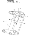
- Figs. 5 - 7 illustrate various embodiments of a screed assembly 10 wherein the coupling portion 42 includes a key 70 and keyway 74 respectively positioned to permit relative linear movement between the coupling members 46, 50 and to inhibit relative rotational movement between the coupling members 46, 50.
- the key 70 and keyway 74 each have at least one tapered or mating wall 78.
- the key 70 and keyway 74 are shown to each have respective corresponding tapered walls 78 along both mating surfaces.
- the key 70 may be driven under power into or released under power from the keyway 74. This may be done in any of a number of conventional manners, including using a hydraulic or electrical actuator to move the key 70 relative to the keyway 74.
- the selected actuator may be bidirectional, or may be unidirectional with a resilient member such as a spring biasing the key in the non-powered direction.
- the key 70 is biased by an actuator 82 having a spring 86 arranged to maintain the key 70 engaged with the keyway 74. This preferred embodiment enables relative linear motion between the coupling members 46, 50 while substantially eliminating rotational movement.
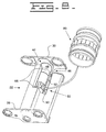
- one of the coaxial cylinders employed as a coupling member 46, 50 may include a chuck 90 adapted to controllably clamp the other of the coaxial cylinders in a manner sufficient to prevent relative movement between the cylinders. With this arrangement, all movement between the first and second coupling members 46, 50 is prevented when the chuck 90 is clamped.
- the chuck 90 may be operated in any conventional manner, for example, using a hydraulic or electrical actuator.
- one of the first and second coupling members 46, 50 may include at least one protrusion 94 and the other of the first and second coupling members 46, 50 may include at least one respective receptacle 98 positioned to receive the protrusion 94.
- this arrangement provides a positive lock against all relative movement between the first and second coupling members 46, 50.
- the length of the coupling portion 42 cannot be varied beyond the preselected relative positions of the protrusion 94 and receptacle 98.
- a typical screed assembly 10 includes both left and right hand screed portions which are essentially mirror images of one another, and this description and the appended claims apply in like manner to both of such left and right hand screed portions.
- the outer extendable screed portions 22 may be retracted using the actuators 54 such that the variable length portion intermediate walls 38 are moved toward the inner end walls 30. In this position, the overall width of the screed assembly 10 is minimized.
- the extendable screed portions 22 are extended using the actuators 54 to provide a desired total paving width.
- the apparatus described above including the coupling portions 42 enables such extended width to accommodate structural overlaps such that the screed assembly 10 may be extended to fully double the retracted width. This occurs when the variable length portion intermediate wall 38 is moved away from the inner end wall 30 in response to the actuator 54 moving the extension screed portion variable length frame 26 longitudinally actually relative to the main screed portion fixed length frame 18 to the fully extended position. In this way, the paving machine screed assembly 10 may be readily adjusted from a minimum paving width up to a maximum paving width that is double the minimum width. According to specific design needs, selected ones of the disclosed embodiments of the present invention facilitate preventing rotational and/or linear movement between the first and second coupling members 46, 50.
Landscapes
- Engineering & Computer Science (AREA)
- Architecture (AREA)
- Civil Engineering (AREA)
- Structural Engineering (AREA)
- Road Paving Machines (AREA)
Priority Applications (3)
| Application Number | Priority Date | Filing Date | Title |
|---|---|---|---|
| EP04011028A EP1596006B1 (fr) | 2004-05-10 | 2004-05-10 | Poutre égaliseuse extensible |
| DE602004027003T DE602004027003D1 (de) | 2004-05-10 | 2004-05-10 | Ausziehbohle |
| US11/058,830 US7287931B2 (en) | 2004-05-10 | 2005-02-16 | Extendable paving screed |
Applications Claiming Priority (1)
| Application Number | Priority Date | Filing Date | Title |
|---|---|---|---|
| EP04011028A EP1596006B1 (fr) | 2004-05-10 | 2004-05-10 | Poutre égaliseuse extensible |
Publications (2)
| Publication Number | Publication Date |
|---|---|
| EP1596006A1 true EP1596006A1 (fr) | 2005-11-16 |
| EP1596006B1 EP1596006B1 (fr) | 2010-05-05 |
Family
ID=34924931
Family Applications (1)
| Application Number | Title | Priority Date | Filing Date |
|---|---|---|---|
| EP04011028A Expired - Lifetime EP1596006B1 (fr) | 2004-05-10 | 2004-05-10 | Poutre égaliseuse extensible |
Country Status (3)
| Country | Link |
|---|---|
| US (1) | US7287931B2 (fr) |
| EP (1) | EP1596006B1 (fr) |
| DE (1) | DE602004027003D1 (fr) |
Cited By (5)
| Publication number | Priority date | Publication date | Assignee | Title |
|---|---|---|---|---|
| EP2955271A1 (fr) * | 2014-06-09 | 2015-12-16 | Wirtgen GmbH | Fixation sélective de châssis |
| US9388538B2 (en) | 2014-06-09 | 2016-07-12 | Wirtgen Gmbh | Frame width adjustment by steering |
| US9388537B2 (en) | 2014-06-09 | 2016-07-12 | Wirtgen Gmbh | Swing over steering |
| US9684308B2 (en) | 2014-11-13 | 2017-06-20 | Wirtgen Gmbh | Transport mode conversion |
| US9969427B1 (en) | 2016-11-16 | 2018-05-15 | Wirtgen Gmbh | Transport conversion mode |
Families Citing this family (6)
| Publication number | Priority date | Publication date | Assignee | Title |
|---|---|---|---|---|
| RU2347033C2 (ru) * | 2003-03-07 | 2009-02-20 | Блау-Нокс Констракшн Эквипмент Корпорейшн | Выдвижное разравнивающее устройство для самоходного транспортного средства для строительства дорожных покрытий |
| US8491221B1 (en) * | 2011-11-03 | 2013-07-23 | Asphalt Joint Compactor, LLC | Compacting screed extension for paving |
| US8591145B1 (en) | 2012-05-07 | 2013-11-26 | Caterpillar Paving Products Inc. | Extension mounting system and method for attaching screed extension to screed |
| US8622649B1 (en) * | 2012-06-19 | 2014-01-07 | Swadick Peeroo | Screen limestone leveling and smoothing tool |
| US8631594B1 (en) * | 2013-02-22 | 2014-01-21 | Sheldon Adam Moyer | Variable width screed attachment |
| CN106702855B (zh) * | 2015-11-12 | 2019-04-09 | 中联重科股份有限公司 | 熨平板拼装装置、熨平板装置和摊铺机 |
Citations (4)
| Publication number | Priority date | Publication date | Assignee | Title |
|---|---|---|---|---|
| US4969773A (en) * | 1988-11-10 | 1990-11-13 | Abg-Werke Gmbh | Laying plank for a road finishing machine |
| US4986695A (en) | 1988-11-10 | 1991-01-22 | Abg-Werke Gmbh | Laying plank for a road finishing machine |
| DE4229464A1 (de) * | 1992-09-03 | 1994-03-10 | Ulm Gmbh Maschbau | Schwarzdeckenfertiger mit ausziehbarer Glättbohle |
| EP0967329A1 (fr) * | 1998-06-23 | 1999-12-29 | Joseph Vögele AG | Poutre lisseuse |
Family Cites Families (6)
| Publication number | Priority date | Publication date | Assignee | Title |
|---|---|---|---|---|
| US4129399A (en) * | 1977-11-14 | 1978-12-12 | Firma Klaus-Gerd Hoes | Mounting bars for road making machines |
| DE3838157A1 (de) * | 1988-11-10 | 1990-05-17 | Abg Werke Gmbh | Einbaubohle fuer einen strassenfertiger |
| GB2250529A (en) | 1990-12-04 | 1992-06-10 | Blaw Knox Const Equipment | Screed plate finisher for paving machine |
| DE4420016A1 (de) * | 1994-06-08 | 1995-12-14 | Dynapac Gmbh | Einbaubohle für einen Straßendeckenfertiger |
| DE29708888U1 (de) | 1997-05-20 | 1997-07-17 | Joseph Vögele AG, 68163 Mannheim | Einbaubohle für einen Straßenfertiger |
| US6203243B1 (en) * | 1998-02-03 | 2001-03-20 | Universal Screed Inc. | Two-stage paving screed extension |
-
2004
- 2004-05-10 DE DE602004027003T patent/DE602004027003D1/de not_active Expired - Lifetime
- 2004-05-10 EP EP04011028A patent/EP1596006B1/fr not_active Expired - Lifetime
-
2005
- 2005-02-16 US US11/058,830 patent/US7287931B2/en not_active Expired - Fee Related
Patent Citations (4)
| Publication number | Priority date | Publication date | Assignee | Title |
|---|---|---|---|---|
| US4969773A (en) * | 1988-11-10 | 1990-11-13 | Abg-Werke Gmbh | Laying plank for a road finishing machine |
| US4986695A (en) | 1988-11-10 | 1991-01-22 | Abg-Werke Gmbh | Laying plank for a road finishing machine |
| DE4229464A1 (de) * | 1992-09-03 | 1994-03-10 | Ulm Gmbh Maschbau | Schwarzdeckenfertiger mit ausziehbarer Glättbohle |
| EP0967329A1 (fr) * | 1998-06-23 | 1999-12-29 | Joseph Vögele AG | Poutre lisseuse |
Cited By (10)
| Publication number | Priority date | Publication date | Assignee | Title |
|---|---|---|---|---|
| EP2955271A1 (fr) * | 2014-06-09 | 2015-12-16 | Wirtgen GmbH | Fixation sélective de châssis |
| US9388539B2 (en) | 2014-06-09 | 2016-07-12 | Wirtgen Gmbh | Selective clamping of chassis |
| US9388538B2 (en) | 2014-06-09 | 2016-07-12 | Wirtgen Gmbh | Frame width adjustment by steering |
| US9388537B2 (en) | 2014-06-09 | 2016-07-12 | Wirtgen Gmbh | Swing over steering |
| US9663906B2 (en) | 2014-06-09 | 2017-05-30 | Wirtgen Gmbh | Selective clamping of chassis |
| US9663905B2 (en) | 2014-06-09 | 2017-05-30 | Wirtgen Gmbh | Swing over steering |
| US9689119B2 (en) | 2014-06-09 | 2017-06-27 | Wirtgen Gmbh | Frame width adjustment by steering |
| US9684308B2 (en) | 2014-11-13 | 2017-06-20 | Wirtgen Gmbh | Transport mode conversion |
| US10496106B2 (en) | 2014-11-13 | 2019-12-03 | Wirtgen Gmbh | Transport mode conversion |
| US9969427B1 (en) | 2016-11-16 | 2018-05-15 | Wirtgen Gmbh | Transport conversion mode |
Also Published As
| Publication number | Publication date |
|---|---|
| US7287931B2 (en) | 2007-10-30 |
| DE602004027003D1 (de) | 2010-06-17 |
| EP1596006B1 (fr) | 2010-05-05 |
| US20050249554A1 (en) | 2005-11-10 |
Similar Documents
| Publication | Publication Date | Title |
|---|---|---|
| US7287931B2 (en) | Extendable paving screed | |
| DE102015006250B4 (de) | Anbaubohleneinheit für einen Straßenfertiger und Straßenfertiger mit einer solchen Anbaubohleneinheit | |
| DE112012003616B4 (de) | Gerät zum Übertragen von Linearlasten | |
| EP1170245B1 (fr) | Châssis de fixation et flèche téléscopique avec châssis de fixation | |
| EP2374657A2 (fr) | Accoudoir et poste de commande doté d'un tel accoudoir | |
| DE202013004195U1 (de) | Verlängerungsbefestigungssystem zum Befestigen einer Glättbodenverlängerung an einer Glättbohle | |
| US6481923B1 (en) | Concrete paving machine | |
| DE202016008572U1 (de) | Bohrmaschine | |
| DE102014006210A1 (de) | Verschiebbares tragsystem für eine glättbohenverlängerung | |
| EP3713709A1 (fr) | Équipement rapporté ainsi que dispositif de manipulation muni d'un équipement rapporté | |
| US6174105B1 (en) | Strike-off device for a paving screed | |
| WO2021069172A1 (fr) | Ensemble de bourrage destiné au bourrage de traverses d'une voie ferrée | |
| WO2001066326A1 (fr) | Surmoule | |
| CN111041946B (zh) | 沥青整平板延伸管调节组件 | |
| EP3152366A1 (fr) | Agencement de tube de vibreur en profondeur | |
| WO2008135017A1 (fr) | Élément mobile de massage et unité de massage comprenant un tel élément mobile de massage | |
| EP4144916A1 (fr) | Agencement de poutre lisseuse pour une finisseuse de route | |
| EP1314682B1 (fr) | Dispositif de déplacement d'un objet et dispositif de télescopage avec un tel dispositif de déplacement | |
| EP4450708A1 (fr) | Engin de construction routière, en particulier finisseur ou rouleau tandem | |
| EP4112816B1 (fr) | Appareil d'excavation de tranchées pour parois moulées et procédé d'excavation d'une paroi moulée dans le sol | |
| JP2008291444A (ja) | 舗装用建設機械のスクリード装置 | |
| EP1403450B1 (fr) | Dispositif de deplacement | |
| DE2621558A1 (de) | Einbaubohle fuer strassenfertiger | |
| EP3550075B1 (fr) | Table de pose avec un dispositif de verrouillage et finisseur de route équipé d'une telle table de pose | |
| EP1033441A2 (fr) | Finisseuse de route vibrante pour asphalte |
Legal Events
| Date | Code | Title | Description |
|---|---|---|---|
| PUAI | Public reference made under article 153(3) epc to a published international application that has entered the european phase |
Free format text: ORIGINAL CODE: 0009012 |
|
| AK | Designated contracting states |
Kind code of ref document: A1 Designated state(s): AT BE BG CH CY CZ DE DK EE ES FI FR GB GR HU IE IT LI LU MC NL PL PT RO SE SI SK TR |
|
| AX | Request for extension of the european patent |
Extension state: AL HR LT LV MK |
|
| RAP1 | Party data changed (applicant data changed or rights of an application transferred) |
Owner name: CATERPILLAR PAVING PRODUCTS INC. |
|
| 17P | Request for examination filed |
Effective date: 20060328 |
|
| AKX | Designation fees paid |
Designated state(s): DE ES FR GB IT |
|
| 17Q | First examination report despatched |
Effective date: 20070312 |
|
| GRAP | Despatch of communication of intention to grant a patent |
Free format text: ORIGINAL CODE: EPIDOSNIGR1 |
|
| GRAS | Grant fee paid |
Free format text: ORIGINAL CODE: EPIDOSNIGR3 |
|
| GRAA | (expected) grant |
Free format text: ORIGINAL CODE: 0009210 |
|
| AK | Designated contracting states |
Kind code of ref document: B1 Designated state(s): DE ES FR GB IT |
|
| REG | Reference to a national code |
Ref country code: GB Ref legal event code: FG4D |
|
| REF | Corresponds to: |
Ref document number: 602004027003 Country of ref document: DE Date of ref document: 20100617 Kind code of ref document: P |
|
| PG25 | Lapsed in a contracting state [announced via postgrant information from national office to epo] |
Ref country code: ES Free format text: LAPSE BECAUSE OF FAILURE TO SUBMIT A TRANSLATION OF THE DESCRIPTION OR TO PAY THE FEE WITHIN THE PRESCRIBED TIME-LIMIT Effective date: 20100816 |
|
| PLBE | No opposition filed within time limit |
Free format text: ORIGINAL CODE: 0009261 |
|
| STAA | Information on the status of an ep patent application or granted ep patent |
Free format text: STATUS: NO OPPOSITION FILED WITHIN TIME LIMIT |
|
| 26N | No opposition filed |
Effective date: 20110208 |
|
| REG | Reference to a national code |
Ref country code: DE Ref legal event code: R097 Ref document number: 602004027003 Country of ref document: DE Effective date: 20110207 |
|
| REG | Reference to a national code |
Ref country code: FR Ref legal event code: PLFP Year of fee payment: 13 |
|
| PGFP | Annual fee paid to national office [announced via postgrant information from national office to epo] |
Ref country code: DE Payment date: 20160524 Year of fee payment: 13 Ref country code: GB Payment date: 20160426 Year of fee payment: 13 |
|
| PGFP | Annual fee paid to national office [announced via postgrant information from national office to epo] |
Ref country code: FR Payment date: 20160428 Year of fee payment: 13 Ref country code: IT Payment date: 20160518 Year of fee payment: 13 |
|
| REG | Reference to a national code |
Ref country code: DE Ref legal event code: R119 Ref document number: 602004027003 Country of ref document: DE |
|
| GBPC | Gb: european patent ceased through non-payment of renewal fee |
Effective date: 20170510 |
|
| REG | Reference to a national code |
Ref country code: FR Ref legal event code: ST Effective date: 20180131 |
|
| PG25 | Lapsed in a contracting state [announced via postgrant information from national office to epo] |
Ref country code: GB Free format text: LAPSE BECAUSE OF NON-PAYMENT OF DUE FEES Effective date: 20170510 Ref country code: DE Free format text: LAPSE BECAUSE OF NON-PAYMENT OF DUE FEES Effective date: 20171201 |
|
| PG25 | Lapsed in a contracting state [announced via postgrant information from national office to epo] |
Ref country code: IT Free format text: LAPSE BECAUSE OF NON-PAYMENT OF DUE FEES Effective date: 20170510 Ref country code: FR Free format text: LAPSE BECAUSE OF NON-PAYMENT OF DUE FEES Effective date: 20170531 |