EP1596014A2 - Jet aerator for water tap - Google Patents
Jet aerator for water tap Download PDFInfo
- Publication number
- EP1596014A2 EP1596014A2 EP05000562A EP05000562A EP1596014A2 EP 1596014 A2 EP1596014 A2 EP 1596014A2 EP 05000562 A EP05000562 A EP 05000562A EP 05000562 A EP05000562 A EP 05000562A EP 1596014 A2 EP1596014 A2 EP 1596014A2
- Authority
- EP
- European Patent Office
- Prior art keywords
- ball
- outer ring
- air
- mixer according
- zone
- Prior art date
- Legal status (The legal status is an assumption and is not a legal conclusion. Google has not performed a legal analysis and makes no representation as to the accuracy of the status listed.)
- Granted
Links
- XLYOFNOQVPJJNP-UHFFFAOYSA-N water Substances O XLYOFNOQVPJJNP-UHFFFAOYSA-N 0.000 title claims abstract description 37
- 238000005276 aerator Methods 0.000 title 1
- 238000007789 sealing Methods 0.000 claims description 9
- 238000010276 construction Methods 0.000 description 5
Images

Classifications
-
- E—FIXED CONSTRUCTIONS
- E03—WATER SUPPLY; SEWERAGE
- E03C—DOMESTIC PLUMBING INSTALLATIONS FOR FRESH WATER OR WASTE WATER; SINKS
- E03C1/00—Domestic plumbing installations for fresh water or waste water; Sinks
- E03C1/02—Plumbing installations for fresh water
- E03C1/08—Jet regulators or jet guides, e.g. anti-splash devices
- E03C1/084—Jet regulators with aerating means
-
- E—FIXED CONSTRUCTIONS
- E03—WATER SUPPLY; SEWERAGE
- E03C—DOMESTIC PLUMBING INSTALLATIONS FOR FRESH WATER OR WASTE WATER; SINKS
- E03C1/00—Domestic plumbing installations for fresh water or waste water; Sinks
- E03C1/02—Plumbing installations for fresh water
- E03C1/08—Jet regulators or jet guides, e.g. anti-splash devices
- E03C2001/082—Outlets connected by an universal joint
Definitions
- the invention relates to a Lucascontinentischer a water fitting in particular for a vanity, a water basin or a tub with a Water outlet, at the front outlet end a on a Pivoting mechanism, in particular pivotably mounted via a joint, Air humidifier flowed through by water is releasably secured.
- the object of the invention is to provide a water fitting with Heilismeischer the to improve the type mentioned above so that a low height achieved and, in particular, the required parts in whole or in part from End of the water outlet are receivable, one of the pivotable adjustable jet-generating Heilismeischer in outlet ends of all Standard fittings can be screwed.
- Such a blender is due to its standard outer shape, Standard outer dimensions and standard external threads in every standard water outlet screwed. Because of that the air blender within the sphere / sphere zone of the joint and no additional Fasteners below the ball are required, a special low height achieved. Furthermore, there is a particularly simple construction with few components.
- the Aerial completely or at least partially within the sphere of Ball joint is mounted and that the outer ring, in which the ball / ball zone is stored, is screwed in the outlet end.
- the one External thread having outer ring in its outer dimensions usual Correspond to air mixers. It is advantageous if the external thread of the Air blender the standard dimensions M24 x 1 or M28 x 1 has.
- the ball is formed by a spherical zone is. It is also advantageous if the ball / ball zone of a particular penetrated cylindrical channel in which the Lucasismeischer rests.
- a particularly simple and stable construction with low height is achieved when the ball / ball zone within an outer ring pivotable is stored.
- the storage on the outlet end facing Side have a sealing ring between the outer ring inner side and the Ball zone outside rests, allowing a simple and secure seal is reached.
- the outer ring with an external thread in a Internal thread of the front end of the water outlet can be screwed.
- a Particularly simple and secure sealing is achieved when the sealing ring when screwing the outer ring into the water outlet at an area in particular a level in the interior of the water outlet is applied and thereby is compressible. It is preferably proposed that the air mixer in the channel of the ball / ball zone can be screwed.
- the front end 1 of a water outlet 2 of a water fitting, in particular a single-lever mixer has a water outlet opening 3, in an air cleaner 4 is releasably attached.
- an air cleaner 4 is releasably attached.
- the cylindrical Outlet opening 3 of the water outlet an internal thread into which an outer ring 5 of the air blender with its external thread can be screwed.
- the Outside dimensions of the Lucasismeischers and thus the outer ring 5 and also the dimensions of the external thread are standard.
- the external thread has the size M24 x 1 or M28 x 1.
- a ball is mounted in the form of a spherical zone 6.
- the ball or the ball zone 6 is securely held in the outer ring 5 and can not fall outward, the diameter of the channel wall 7 tapers of the outer ring 5 outwardly to form a narrowest point 8, from the from the channel wall 7 conically widens outwards and thus there a conical extension 9 forms.
- the inside of the Outer ring 5 a concave bearing for the ball / ball zone. 6
- the rotatably mounted in the channel wall 7 ball or ball zone 6 is held towards the water outlet 2 through a coaxial sealing ring 10, the at Screwing the outer ring 5 in a gap between the outer ring 5 and ball or ball zone 6 sealingly pressed by that when screwing the Top of the sealing ring 10 against a stage 11 of the water outlet to Plant arrives.
- the plant reaches of the sealing ring 10 at the stage 11, that no water between the outer ring and outlet opening 3 can escape.
- the ball or ball zone 6 has an integrally formed outwards cylindrical sleeve-shaped portion 12, the pivoting of the Ball / ball zone reaches the conical extension 9 to the plant, so that so that the maximum pivoting range of the ball / ball zone is determined.
- the pivotable part of the air blender also be pivoted by another type of joint, in particular by a hinge axis with two lateral pivot pins.
- the construction according to the invention achieves particularly low Outside dimensions and in particular a particularly low height, as the Components are all in one another or plugged and / or screwed.
- FIG. 3 and 4 A constructive alternative, Fig. 3 and 4.
- the outside of the Lucasismeischers 4 part spherical or formed as a spherical zone and in the Inside the outer ring 5 stored without there being an intermediate part in shape the ball or a ball ring 6 is required.
- bearings are on the outside of the Heilismeischers 4 on opposite sides two cylindrical or partially cylindrical projections 15 formed in corresponding recesses 16 eino positively in the inside of the outer ring 5.
Landscapes
- Health & Medical Sciences (AREA)
- Life Sciences & Earth Sciences (AREA)
- Engineering & Computer Science (AREA)
- Hydrology & Water Resources (AREA)
- Public Health (AREA)
- Water Supply & Treatment (AREA)
- Domestic Plumbing Installations (AREA)
- Joints Allowing Movement (AREA)
Abstract
Description
Die Erfindung betrifft einen Luftbeimischer einer Wasserarmatur insbesondere für einen Waschtisch, ein Wasserbecken oder eine Wanne mit einem Wasserauslauf, an dessen vorderem Auslaufende ein über ein Schwenkmechanismus insbesondere über ein Gelenk verschwenkbar gelagerter, vom Wasser durchströmter Luftbeimischer lösbar befestigt ist.The invention relates to a Luftbeimischer a water fitting in particular for a vanity, a water basin or a tub with a Water outlet, at the front outlet end a on a Pivoting mechanism, in particular pivotably mounted via a joint, Air humidifier flowed through by water is releasably secured.
Es ist bekannt, einen Luftbeimischer an dem vorderen Ende eines Wasserauslaufes einer Mischarmatur über ein Kugelgelenk zu befestigen. Hierbei ist das Kugelgelenk am Wasserauslauf befestigt und die Kugel besitzt einen Kanal durch den das Wasser strömt. Unterhalb der Kugel ist ein Luftbeimischer angeordnet, dessen Ausstrahlrichtung aufgrund des Kugelgelenkes verstellbar ist. Eine solche Konstruktion führt zu einer erheblichen Bauhöhe, so dass ein verhältnismäßig großes Teil am Ende des Wasserauslaufes befestigt ist.It is known, an air blender at the front end of a To fix a water outlet of a mixing valve via a ball joint. Here, the ball joint is attached to the water outlet and the ball has a channel through which the water flows. Below the ball is a Luftbeimischer arranged whose beam direction due to the Ball joint is adjustable. Such a construction leads to a considerable Height, so a relatively large part at the end of the Water outlet is attached.
Aufgabe der Erfindung ist es, eine Wasserarmatur mit Luftbeimischer der eingangs genannten Art so zu verbessern, dass eine geringe Bauhöhe erzielt wird, und insbesondere die erforderlichen Teile vollständig oder teilweise vom Ende des Wasserauslaufes aufnehmbar sind, wobei der einen verschwenkbar einstellbaren Strahl erzeugende Luftbeimischer in Auslaufenden aller Standardarmaturen einschraubbar ist. The object of the invention is to provide a water fitting with Luftbeimischer the to improve the type mentioned above so that a low height achieved and, in particular, the required parts in whole or in part from End of the water outlet are receivable, one of the pivotable adjustable jet-generating Luftbeimischer in outlet ends of all Standard fittings can be screwed.
Diese Aufgabe wird erfindungsgemäß dadurch gelöst, dass der verschwenkbare Luftbeimischer innerhalb eines Außenringes gelagert ist, der im Auslaufende befestigt insbesondere eingeschraubt ist.This object is achieved in that the pivotable Luftbeimischer is stored within an outer ring, in the outlet end fastened in particular is screwed.
Ein solcher Luftbeimischer ist auf Grund seiner Standard-Außenform, Standardaußenabmessungen und Standard-Außengewinde in jeden Standard-Wasserauslauf einschraubbar. Aufgrund dessen, dass der Luftbeimischer innerhalb der Kugel/Kugelzone des Gelenkes liegt und keine zusätzlichen Befestigungsmittel unterhalb der Kugel erforderlich sind, wird eine besonders geringe Bauhöhe erreicht. Ferner besteht eine besonders einfache Konstruktion mit wenigen Bauteilen.Such a blender is due to its standard outer shape, Standard outer dimensions and standard external threads in every standard water outlet screwed. Because of that the air blender within the sphere / sphere zone of the joint and no additional Fasteners below the ball are required, a special low height achieved. Furthermore, there is a particularly simple construction with few components.
Von Vorteil ist, wenn die Außenseite des Luftbeimischers teilkugelförmig ist und mit dieser Außenseite im Außenring verschwenkbar gelagert ist. Hierdurch bildet der Luftbeimischer selber das Innenteil des Kugelgelenkes, so dass der Luftbeimischer ohne Zwischenteil im Außenring gelagert ist. Dies führt zu einer besonders einfachen und preiswerten Konstruktion mit wenig Teilen.It is advantageous if the outside of the air blender is partially spherical and is mounted pivotably with this outside in the outer ring. This forms the Luftbeimischer itself the inner part of the ball joint, so that the Luftbeimischer is stored without intermediate part in the outer ring. This leads to a particularly simple and inexpensive construction with few parts.
Besonders vorteilhaft ist ein Luftbeimischer mit Kugelgelenk, wobei der Luftbeimischer vollständig oder zumindest teilweise innerhalb der Kugel des Kugelgelenkes gelagert ist und dass der Außenring, in dem die Kugel/Kugelzone gelagert ist, im Auslaufende eingeschraubt ist. Hierbei kann der ein Außengewinde aufweisende Außenring in seinen Außenabmessungen üblichen Luftbeimischern entsprechen. Von Vorteil ist dabei, wenn das Außengewinde des Luftbeimischers die Standardabmessungen M24 x 1 oder M28 x 1 aufweist.Particularly advantageous is a Luftbeimischer with ball joint, wherein the Aerial completely or at least partially within the sphere of Ball joint is mounted and that the outer ring, in which the ball / ball zone is stored, is screwed in the outlet end. Here, the one External thread having outer ring in its outer dimensions usual Correspond to air mixers. It is advantageous if the external thread of the Air blender the standard dimensions M24 x 1 or M28 x 1 has.
Vorzugsweise wird vorgeschlagen, dass die Kugel von einer Kugelzone gebildet ist. Auch ist von Vorteil, wenn die Kugel/Kugelzone von einem insbesondere zylindrischen Kanal durchdrungen ist, in dem der Luftbeimischer einliegt.It is preferably proposed that the ball is formed by a spherical zone is. It is also advantageous if the ball / ball zone of a particular penetrated cylindrical channel in which the Luftbeimischer rests.
Eine besonders einfache und stabile Konstruktion bei geringer Bauhöhe wird erreicht, wenn die Kugel/Kugelzone innerhalb eines Außenringes verschwenkbar gelagert ist. Hierbei kann die Lagerung auf der dem Auslaufende zugewandten Seite einen Dichtring aufweisen, der zwischen der Außenringinnenseite und der Kugelzonenaußenseite einliegt, so dass eine einfache und sichere Abdichtung erreicht wird.A particularly simple and stable construction with low height is achieved when the ball / ball zone within an outer ring pivotable is stored. Here, the storage on the outlet end facing Side have a sealing ring between the outer ring inner side and the Ball zone outside rests, allowing a simple and secure seal is reached.
Auch ist von Vorteil, wenn an der Wasseraustrittsseite an der Kugelzone ein zylindrischer, insbesondere buchsenförmiger Bereich angeformt ist. Hierbei kann die Kanalwand des Außenringes im Auslaufbereich nach außen sich erweiternd, insbesondere konisch geformt sein, wobei an diesem sich erweiternden Kanalwandbereich der buchsenförmige Bereich der Kugel/Kugelzone beim Verschwenken zur Anlage gelangt.It is also advantageous if at the water outlet side at the spherical zone cylindrical, in particular bush-shaped area is formed. Here can widening the channel wall of the outer ring in the outlet area to the outside, be conically shaped in particular, wherein widening at this Channel wall area of the bush-shaped area of the ball / ball zone during Pivoting reaches the plant.
Ferner ist von Vorteil, wenn der Außenring mit einem Außengewinde in ein Innengewinde des vorderen Endes des Wasserauslaufes einschraubbar ist. Eine besonders einfache und sichere Abdichtung wird erreicht, wenn der Dichtring beim Einschrauben des Außenringes in den Wasserauslauf an einem Bereich, insbesondere einer Stufe im Inneren des Wasserauslaufes anliegt und hierdurch verpressbar ist. Vorzugsweise wird vorgeschlagen, dass der Luftbeimischer in dem Kanal der Kugel/Kugelzone einschraubbar ist.It is also advantageous if the outer ring with an external thread in a Internal thread of the front end of the water outlet can be screwed. A Particularly simple and secure sealing is achieved when the sealing ring when screwing the outer ring into the water outlet at an area in particular a level in the interior of the water outlet is applied and thereby is compressible. It is preferably proposed that the air mixer in the channel of the ball / ball zone can be screwed.
Eine einfache Lagerung wird erreicht, wenn an der Außenseite des Luftbeimischers ein insbesondere zylindrischer oder teilzylindrischer Abschnitt vorsteht, der in einer entsprechend geformten Ausnehmung der Kugel bzw. des Außenringes als Lager einliegt.A simple storage is achieved when on the outside of the Luftbeimischers a particular cylindrical or partially cylindrical section projecting in a correspondingly shaped recess of the ball or the Outer ring rests as a bearing.
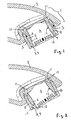
Ein Ausführungsbeispiel der Erfindung ist in der Zeichnung in senkrechtem Schnitt dargestellt und wird im folgenden näher beschrieben. Es zeigen
Figur 1- den Luftbeimischer in gerader Ausrichtung und
Figur 2- den Luftbeimischer in verschwenkter Stellung,
Figur 3- eine alternative Ausführung mit direkter Lagerung des Luftbeimischers im Außenring,
Figur 4- die Ausführung nach Fig. 3 mit einer perspektivischen Darstellung des Luftbeimischers.
- FIG. 1
- the air mixer in straight alignment and
- FIG. 2
- the air mixer in a pivoted position,
- FIG. 3
- an alternative embodiment with direct mounting of the air blender in the outer ring,
- FIG. 4
- the embodiment of FIG. 3 with a perspective view of the air blender.
Das vordere Ende 1 eines Wasserauslaufes 2 einer Wasserarmatur,
insbesondere eines Einhebelmischers besitzt eine Wasseraustrittsöffnung 3, in
der ein Luftbeimischer 4 lösbar befestigt ist. Hierzu besitzt die zylindrische
Austrittsöffnung 3 des Wasserauslaufes ein Innengewinde, in das ein Außenring
5 des Luftbeimischers mit seinem Außengewinde einschraubbar ist. Die
Außenabmessungen des Luftbeimischers und damit des Außenringes 5 und
auch die Abmessungen des Außengewindes sind Standard. Das Außengewinde
hat hierbei die Größe M24 x 1 oder M28 x 1.The
Im Innern des Außenringes 5 ist eine Kugel in Form einer Kugelzone 6 gelagert.
Damit die Kugel bzw. die Kugelzone 6 im Außenring 5 sicher gehalten ist und
nicht nach außen fallen kann, verjüngt sich der Durchmesser der Kanalwand 7
des Außenringes 5 nach außen hin um eine engste Stelle 8 zu bilden, von der
aus der Kanalwand 7 sich nach außen hin konisch erweitert und damit dort eine
konische Erweiterung 9 bildet. Vorzugsweise bildet die Innenseite des
Außenringes 5 eine konkave Lagerung für die Kugel/Kugelzone 6.In the interior of the
Die in der Kanalwand 7 drehverstellbar gelagerte Kugel bzw. Kugelzone 6 ist
zum Wasserauslauf 2 hin durch einen koaxialen Dichtring 10 gehalten, der beim
Einschrauben des Außenringes 5 in einen Spalt zwischen Außenring 5 und Kugel
bzw. Kugelzone 6 dichtend dadurch gedrückt wird, dass beim Einschrauben die
Oberseite des Dichtringes 10 gegen eine Stufe 11 des Wasserauslaufes zur
Anlage gelangt. Damit erreicht der im Querschnitt dreieckförmige Dichtring 10
eine sichere Abdichtung zwischen Kugel und Außenring, so dass das Wasser
durch den Luftbeimischer 4 hindurchströmt. Darüber hinaus erreicht die Anlage
des Dichtringes 10 an der Stufe 11, dass auch kein Wasser zwischen Außenring
und Austrittsöffnung 3 austreten kann.The rotatably mounted in the channel wall 7 ball or
Die Kugel, bzw. Kugelzone 6 besitzt nach außen hin einen angeformten
zylindrischen buchsenförmigen Bereich 12, der beim Verschwenken der
Kugel/Kugelzone an die konische Erweiterung 9 zur Anlage gelangt, so dass
damit der maximale Schwenkbereich der Kugel/Kugelzone bestimmt ist.The ball or
Statt eines Kugelgelenkes kann der verschwenkbare Teil des Luftbeimischers auch durch eine andere Gelenkart verschwenkbar gelagert sein, insbesondere durch eine Gelenkachse mit zwei seitlichen Gelenkzapfen.Instead of a ball joint, the pivotable part of the air blender Also be pivoted by another type of joint, in particular by a hinge axis with two lateral pivot pins.
Die erfindungsgemäße Konstruktion erreicht besonders geringe Außenabmessungen und insbesondere eine besonders geringe Bauhöhe, da die Bauteile alle ineinander liegen bzw. gesteckt und/oder geschraubt sind.The construction according to the invention achieves particularly low Outside dimensions and in particular a particularly low height, as the Components are all in one another or plugged and / or screwed.
Eine konstruktive Alternative zeigen Fig. 3 und 4. Hier ist die Außenseite des
Luftbeimischers 4 teilkugelförmig bzw. als Kugelzone ausgebildet und in dem
Inneren des Außenringes 5 gelagert, ohne dass es eines Zwischenteils in Form
der Kugel bzw. eines Kugelringes 6 bedarf. Als Lager sind an der Außenseite des
Luftbeimischers 4 auf gegenüber liegenden Seiten zwei zylindrische bzw.
teilzylindrische Vorsprünge 15 angeformt, die in entsprechenden Ausnehmungen
16 in der Innenseite des Außenringes 5 formschlüssig einliegen. Alternativ bildet
die Innenwand des Außenringes 5 eine konkave Ringausnehmung für die
kugelzonenförmige Außenseite des Luftbeimischers 4.A constructive alternative, Fig. 3 and 4. Here is the outside of the
Claims (16)
Priority Applications (7)
| Application Number | Priority Date | Filing Date | Title |
|---|---|---|---|
| EP14000122.3A EP2770124A1 (en) | 2004-03-25 | 2005-03-15 | Faucet with jet aerator |
| CN2005800080965A CN101415890B (en) | 2004-03-25 | 2005-03-15 | Air mixer |
| US10/599,091 US8006922B2 (en) | 2004-03-25 | 2005-03-15 | Aerator of a plumbing fixture |
| BRPI0507939-0A BRPI0507939A (en) | 2004-03-25 | 2005-03-15 | aerator for a water tap |
| AU2005225518A AU2005225518B2 (en) | 2004-03-25 | 2005-03-15 | Aerator of a plumbing fixture |
| PCT/EP2005/002740 WO2005093174A2 (en) | 2004-03-25 | 2005-03-15 | Aerator for a plumbing fixture |
| EP05716070.7A EP1738036B1 (en) | 2004-03-25 | 2005-03-15 | Aerator fo a plumbing fixture |
Applications Claiming Priority (4)
| Application Number | Priority Date | Filing Date | Title |
|---|---|---|---|
| DE102004015183 | 2004-03-25 | ||
| DE102004015183 | 2004-03-25 | ||
| DE102004039915 | 2004-08-18 | ||
| DE102004039915A DE102004039915A1 (en) | 2004-03-25 | 2004-08-18 | Aerial admirer of a water faucet |
Publications (3)
| Publication Number | Publication Date |
|---|---|
| EP1596014A2 true EP1596014A2 (en) | 2005-11-16 |
| EP1596014A3 EP1596014A3 (en) | 2006-03-29 |
| EP1596014B1 EP1596014B1 (en) | 2014-06-25 |
Family
ID=34933275
Family Applications (1)
| Application Number | Title | Priority Date | Filing Date |
|---|---|---|---|
| EP20050000562 Expired - Lifetime EP1596014B1 (en) | 2004-03-25 | 2005-01-13 | Jet aerator for water tap |
Country Status (3)
| Country | Link |
|---|---|
| EP (1) | EP1596014B1 (en) |
| CN (1) | CN101415890B (en) |
| DE (1) | DE102004039915A1 (en) |
Cited By (2)
| Publication number | Priority date | Publication date | Assignee | Title |
|---|---|---|---|---|
| WO2006092316A2 (en) | 2005-03-04 | 2006-09-08 | Neoperl Gmbh | Sanitary water outlet comprising a pivotable water conduit |
| WO2014142766A1 (en) * | 2013-03-12 | 2014-09-18 | Jeremić Dragan | Insert with rotating mesh and rotating mesh for aerators in sanitary batteries |
Families Citing this family (5)
| Publication number | Priority date | Publication date | Assignee | Title |
|---|---|---|---|---|
| DE202015007677U1 (en) | 2015-11-05 | 2017-02-07 | Neoperl Gmbh | aerator |
| DE102015014309B4 (en) * | 2015-11-05 | 2020-01-16 | Neoperl Gmbh | aerator |
| CN108951771B (en) * | 2018-08-01 | 2020-12-08 | 九牧厨卫股份有限公司 | A self-cleaning bubbler |
| WO2020024617A1 (en) * | 2018-08-01 | 2020-02-06 | 九牧厨卫股份有限公司 | Bubbler capable of self-cleaning |
| CN112323920A (en) * | 2020-12-03 | 2021-02-05 | 菏泽市智慧工匠科技有限公司 | Multifunctional embedded water-saving bubbler capable of adjusting angles in multiple positions |
Citations (2)
| Publication number | Priority date | Publication date | Assignee | Title |
|---|---|---|---|---|
| DE3205205A1 (en) | 1982-02-13 | 1983-08-25 | Hans Grohe Gmbh & Co Kg, 7622 Schiltach | Fitting outlet |
| EP0190965A1 (en) | 1985-02-01 | 1986-08-13 | Les Robinets Presto Société Anonyme | Device for mounting an aerator in the discharge nozzle of a water tap |
Family Cites Families (1)
| Publication number | Priority date | Publication date | Assignee | Title |
|---|---|---|---|---|
| CN2125461U (en) * | 1992-06-10 | 1992-12-23 | 王宇 | Adjustable high efficient water saving device |
-
2004
- 2004-08-18 DE DE102004039915A patent/DE102004039915A1/en not_active Withdrawn
-
2005
- 2005-01-13 EP EP20050000562 patent/EP1596014B1/en not_active Expired - Lifetime
- 2005-03-15 CN CN2005800080965A patent/CN101415890B/en not_active Expired - Fee Related
Patent Citations (2)
| Publication number | Priority date | Publication date | Assignee | Title |
|---|---|---|---|---|
| DE3205205A1 (en) | 1982-02-13 | 1983-08-25 | Hans Grohe Gmbh & Co Kg, 7622 Schiltach | Fitting outlet |
| EP0190965A1 (en) | 1985-02-01 | 1986-08-13 | Les Robinets Presto Société Anonyme | Device for mounting an aerator in the discharge nozzle of a water tap |
Cited By (6)
| Publication number | Priority date | Publication date | Assignee | Title |
|---|---|---|---|---|
| WO2006092316A2 (en) | 2005-03-04 | 2006-09-08 | Neoperl Gmbh | Sanitary water outlet comprising a pivotable water conduit |
| WO2006092316A3 (en) * | 2005-03-04 | 2006-11-30 | Neoperl Gmbh | Sanitary water outlet comprising a pivotable water conduit |
| US8205810B2 (en) | 2005-03-04 | 2012-06-26 | Neoperl Gmbh | Sanitary water outlet |
| US8528840B2 (en) | 2005-03-04 | 2013-09-10 | Neoperl Gmbh | Sanitary water outlet |
| WO2014142766A1 (en) * | 2013-03-12 | 2014-09-18 | Jeremić Dragan | Insert with rotating mesh and rotating mesh for aerators in sanitary batteries |
| US10400431B2 (en) | 2013-03-12 | 2019-09-03 | Neoperl Gmbh | Insert with rotating mesh and rotating mesh for aerators in sanitary batteries |
Also Published As
| Publication number | Publication date |
|---|---|
| CN101415890B (en) | 2012-01-11 |
| EP1596014B1 (en) | 2014-06-25 |
| CN101415890A (en) | 2009-04-22 |
| EP1596014A3 (en) | 2006-03-29 |
| DE102004039915A1 (en) | 2005-10-27 |
Similar Documents
| Publication | Publication Date | Title |
|---|---|---|
| EP2770124A1 (en) | Faucet with jet aerator | |
| EP1817466B1 (en) | Sanitary water outlet comprising a pivotable water conduit | |
| EP0432553B1 (en) | Sanitary fixture | |
| DE3790241C2 (en) | Tap with orientable flow nozzle | |
| CH682682A5 (en) | Sanitary fitting. | |
| EP0014399B1 (en) | Mixing valve for fluids | |
| EP3290598A2 (en) | Connection socket for a bathroom fitting with ground standing fitting column | |
| EP1596014A2 (en) | Jet aerator for water tap | |
| DE2940338A1 (en) | WASHBASIN FITTING | |
| DE3112614C2 (en) | ||
| EP0012890B1 (en) | Stationary water outlet valve, particularly for sanitary purposes | |
| DE102006021801B4 (en) | Sanitary outlet unit | |
| DE3205205C2 (en) | Faucet outlet | |
| DE3908009C2 (en) | Sanitary valve | |
| DE102004041796B4 (en) | plumbing fixture | |
| EP1031665A2 (en) | Device for sucking and mixing of an additive in a fluid conduit | |
| DE1952974A1 (en) | Spout device | |
| DE7827331U1 (en) | SINGLE-HOLE MIXING TAP WITH ONE-HAND OPERATION | |
| DE20300448U1 (en) | Variable position hot water tap spout screw-fit rose | |
| DE10156786B4 (en) | Fitting body, in particular for a faucet, and valve assembly | |
| DE202005019372U1 (en) | Pendulum shower equipment e.g. for shower, has attachment part and shower components with attachment part has base plate having water opening and support | |
| DE29515243U1 (en) | Spout for a sanitary fitting | |
| DE202006007478U1 (en) | Sanitary outlet unit e.g. hand or kitchen shower, has aeration device provided in outlet fitting and/or in one of water lines that is guided by outlet fitting in flow direction with specific distance from water outlet | |
| CH385758A (en) | Actuating device for the drain valve on a container, in particular a wash bowl | |
| EP1217131A2 (en) | Sanitary armature with swivelling spout |
Legal Events
| Date | Code | Title | Description |
|---|---|---|---|
| PUAI | Public reference made under article 153(3) epc to a published international application that has entered the european phase |
Free format text: ORIGINAL CODE: 0009012 |
|
| AK | Designated contracting states |
Kind code of ref document: A2 Designated state(s): AT BE BG CH CY CZ DE DK EE ES FI FR GB GR HU IE IS IT LI LT LU MC NL PL PT RO SE SI SK TR |
|
| AX | Request for extension of the european patent |
Extension state: AL BA HR LV MK YU |
|
| PUAL | Search report despatched |
Free format text: ORIGINAL CODE: 0009013 |
|
| AK | Designated contracting states |
Kind code of ref document: A3 Designated state(s): AT BE BG CH CY CZ DE DK EE ES FI FR GB GR HU IE IS IT LI LT LU MC NL PL PT RO SE SI SK TR |
|
| AX | Request for extension of the european patent |
Extension state: AL BA HR LV MK YU |
|
| 17P | Request for examination filed |
Effective date: 20060415 |
|
| RAP1 | Party data changed (applicant data changed or rights of an application transferred) |
Owner name: NEOPERL GMBH |
|
| AKX | Designation fees paid |
Designated state(s): AT BE BG CH CY CZ DE DK EE ES FI FR GB GR HU IE IS IT LI LT LU MC NL PL PT RO SE SI SK TR |
|
| 17Q | First examination report despatched |
Effective date: 20120207 |
|
| GRAP | Despatch of communication of intention to grant a patent |
Free format text: ORIGINAL CODE: EPIDOSNIGR1 |
|
| INTG | Intention to grant announced |
Effective date: 20140219 |
|
| GRAS | Grant fee paid |
Free format text: ORIGINAL CODE: EPIDOSNIGR3 |
|
| GRAA | (expected) grant |
Free format text: ORIGINAL CODE: 0009210 |
|
| AK | Designated contracting states |
Kind code of ref document: B1 Designated state(s): AT BE BG CH CY CZ DE DK EE ES FI FR GB GR HU IE IS IT LI LT LU MC NL PL PT RO SE SI SK TR |
|
| REG | Reference to a national code |
Ref country code: GB Ref legal event code: FG4D Free format text: NOT ENGLISH |
|
| REG | Reference to a national code |
Ref country code: CH Ref legal event code: EP |
|
| REG | Reference to a national code |
Ref country code: AT Ref legal event code: REF Ref document number: 674809 Country of ref document: AT Kind code of ref document: T Effective date: 20140715 |
|
| REG | Reference to a national code |
Ref country code: IE Ref legal event code: FG4D Free format text: LANGUAGE OF EP DOCUMENT: GERMAN |
|
| REG | Reference to a national code |
Ref country code: DE Ref legal event code: R096 Ref document number: 502005014405 Country of ref document: DE Effective date: 20140807 |
|
| PG25 | Lapsed in a contracting state [announced via postgrant information from national office to epo] |
Ref country code: FI Free format text: LAPSE BECAUSE OF FAILURE TO SUBMIT A TRANSLATION OF THE DESCRIPTION OR TO PAY THE FEE WITHIN THE PRESCRIBED TIME-LIMIT Effective date: 20140625 Ref country code: GR Free format text: LAPSE BECAUSE OF FAILURE TO SUBMIT A TRANSLATION OF THE DESCRIPTION OR TO PAY THE FEE WITHIN THE PRESCRIBED TIME-LIMIT Effective date: 20140926 Ref country code: CY Free format text: LAPSE BECAUSE OF FAILURE TO SUBMIT A TRANSLATION OF THE DESCRIPTION OR TO PAY THE FEE WITHIN THE PRESCRIBED TIME-LIMIT Effective date: 20140625 Ref country code: LT Free format text: LAPSE BECAUSE OF FAILURE TO SUBMIT A TRANSLATION OF THE DESCRIPTION OR TO PAY THE FEE WITHIN THE PRESCRIBED TIME-LIMIT Effective date: 20140625 |
|
| REG | Reference to a national code |
Ref country code: NL Ref legal event code: VDEP Effective date: 20140625 |
|
| REG | Reference to a national code |
Ref country code: LT Ref legal event code: MG4D |
|
| PG25 | Lapsed in a contracting state [announced via postgrant information from national office to epo] |
Ref country code: SE Free format text: LAPSE BECAUSE OF FAILURE TO SUBMIT A TRANSLATION OF THE DESCRIPTION OR TO PAY THE FEE WITHIN THE PRESCRIBED TIME-LIMIT Effective date: 20140625 |
|
| PG25 | Lapsed in a contracting state [announced via postgrant information from national office to epo] |
Ref country code: EE Free format text: LAPSE BECAUSE OF FAILURE TO SUBMIT A TRANSLATION OF THE DESCRIPTION OR TO PAY THE FEE WITHIN THE PRESCRIBED TIME-LIMIT Effective date: 20140625 Ref country code: CZ Free format text: LAPSE BECAUSE OF FAILURE TO SUBMIT A TRANSLATION OF THE DESCRIPTION OR TO PAY THE FEE WITHIN THE PRESCRIBED TIME-LIMIT Effective date: 20140625 Ref country code: PT Free format text: LAPSE BECAUSE OF FAILURE TO SUBMIT A TRANSLATION OF THE DESCRIPTION OR TO PAY THE FEE WITHIN THE PRESCRIBED TIME-LIMIT Effective date: 20141027 Ref country code: RO Free format text: LAPSE BECAUSE OF FAILURE TO SUBMIT A TRANSLATION OF THE DESCRIPTION OR TO PAY THE FEE WITHIN THE PRESCRIBED TIME-LIMIT Effective date: 20140625 Ref country code: SK Free format text: LAPSE BECAUSE OF FAILURE TO SUBMIT A TRANSLATION OF THE DESCRIPTION OR TO PAY THE FEE WITHIN THE PRESCRIBED TIME-LIMIT Effective date: 20140625 Ref country code: ES Free format text: LAPSE BECAUSE OF FAILURE TO SUBMIT A TRANSLATION OF THE DESCRIPTION OR TO PAY THE FEE WITHIN THE PRESCRIBED TIME-LIMIT Effective date: 20140625 |
|
| PG25 | Lapsed in a contracting state [announced via postgrant information from national office to epo] |
Ref country code: IS Free format text: LAPSE BECAUSE OF FAILURE TO SUBMIT A TRANSLATION OF THE DESCRIPTION OR TO PAY THE FEE WITHIN THE PRESCRIBED TIME-LIMIT Effective date: 20141025 Ref country code: PL Free format text: LAPSE BECAUSE OF FAILURE TO SUBMIT A TRANSLATION OF THE DESCRIPTION OR TO PAY THE FEE WITHIN THE PRESCRIBED TIME-LIMIT Effective date: 20140625 Ref country code: NL Free format text: LAPSE BECAUSE OF FAILURE TO SUBMIT A TRANSLATION OF THE DESCRIPTION OR TO PAY THE FEE WITHIN THE PRESCRIBED TIME-LIMIT Effective date: 20140625 |
|
| REG | Reference to a national code |
Ref country code: DE Ref legal event code: R097 Ref document number: 502005014405 Country of ref document: DE |
|
| PG25 | Lapsed in a contracting state [announced via postgrant information from national office to epo] |
Ref country code: DK Free format text: LAPSE BECAUSE OF FAILURE TO SUBMIT A TRANSLATION OF THE DESCRIPTION OR TO PAY THE FEE WITHIN THE PRESCRIBED TIME-LIMIT Effective date: 20140625 |
|
| PLBE | No opposition filed within time limit |
Free format text: ORIGINAL CODE: 0009261 |
|
| STAA | Information on the status of an ep patent application or granted ep patent |
Free format text: STATUS: NO OPPOSITION FILED WITHIN TIME LIMIT |
|
| 26N | No opposition filed |
Effective date: 20150326 |
|
| PG25 | Lapsed in a contracting state [announced via postgrant information from national office to epo] |
Ref country code: BE Free format text: LAPSE BECAUSE OF NON-PAYMENT OF DUE FEES Effective date: 20150131 |
|
| REG | Reference to a national code |
Ref country code: CH Ref legal event code: PL |
|
| PG25 | Lapsed in a contracting state [announced via postgrant information from national office to epo] |
Ref country code: LU Free format text: LAPSE BECAUSE OF FAILURE TO SUBMIT A TRANSLATION OF THE DESCRIPTION OR TO PAY THE FEE WITHIN THE PRESCRIBED TIME-LIMIT Effective date: 20150113 |
|
| GBPC | Gb: european patent ceased through non-payment of renewal fee |
Effective date: 20150113 |
|
| PG25 | Lapsed in a contracting state [announced via postgrant information from national office to epo] |
Ref country code: MC Free format text: LAPSE BECAUSE OF FAILURE TO SUBMIT A TRANSLATION OF THE DESCRIPTION OR TO PAY THE FEE WITHIN THE PRESCRIBED TIME-LIMIT Effective date: 20140625 |
|
| PG25 | Lapsed in a contracting state [announced via postgrant information from national office to epo] |
Ref country code: GB Free format text: LAPSE BECAUSE OF NON-PAYMENT OF DUE FEES Effective date: 20150113 Ref country code: CH Free format text: LAPSE BECAUSE OF NON-PAYMENT OF DUE FEES Effective date: 20150131 Ref country code: LI Free format text: LAPSE BECAUSE OF NON-PAYMENT OF DUE FEES Effective date: 20150131 |
|
| REG | Reference to a national code |
Ref country code: FR Ref legal event code: ST Effective date: 20150930 |
|
| REG | Reference to a national code |
Ref country code: IE Ref legal event code: MM4A |
|
| PG25 | Lapsed in a contracting state [announced via postgrant information from national office to epo] |
Ref country code: FR Free format text: LAPSE BECAUSE OF NON-PAYMENT OF DUE FEES Effective date: 20150202 Ref country code: SI Free format text: LAPSE BECAUSE OF FAILURE TO SUBMIT A TRANSLATION OF THE DESCRIPTION OR TO PAY THE FEE WITHIN THE PRESCRIBED TIME-LIMIT Effective date: 20140625 |
|
| PG25 | Lapsed in a contracting state [announced via postgrant information from national office to epo] |
Ref country code: IE Free format text: LAPSE BECAUSE OF NON-PAYMENT OF DUE FEES Effective date: 20150113 |
|
| REG | Reference to a national code |
Ref country code: AT Ref legal event code: MM01 Ref document number: 674809 Country of ref document: AT Kind code of ref document: T Effective date: 20150113 |
|
| PG25 | Lapsed in a contracting state [announced via postgrant information from national office to epo] |
Ref country code: AT Free format text: LAPSE BECAUSE OF NON-PAYMENT OF DUE FEES Effective date: 20150113 |
|
| PG25 | Lapsed in a contracting state [announced via postgrant information from national office to epo] |
Ref country code: HU Free format text: LAPSE BECAUSE OF FAILURE TO SUBMIT A TRANSLATION OF THE DESCRIPTION OR TO PAY THE FEE WITHIN THE PRESCRIBED TIME-LIMIT; INVALID AB INITIO Effective date: 20050113 Ref country code: BG Free format text: LAPSE BECAUSE OF FAILURE TO SUBMIT A TRANSLATION OF THE DESCRIPTION OR TO PAY THE FEE WITHIN THE PRESCRIBED TIME-LIMIT Effective date: 20140625 |
|
| PGFP | Annual fee paid to national office [announced via postgrant information from national office to epo] |
Ref country code: TR Payment date: 20180109 Year of fee payment: 14 |
|
| PGFP | Annual fee paid to national office [announced via postgrant information from national office to epo] |
Ref country code: DE Payment date: 20191213 Year of fee payment: 16 Ref country code: IT Payment date: 20200122 Year of fee payment: 16 |
|
| REG | Reference to a national code |
Ref country code: DE Ref legal event code: R119 Ref document number: 502005014405 Country of ref document: DE |
|
| PG25 | Lapsed in a contracting state [announced via postgrant information from national office to epo] |
Ref country code: DE Free format text: LAPSE BECAUSE OF NON-PAYMENT OF DUE FEES Effective date: 20210803 |
|
| PG25 | Lapsed in a contracting state [announced via postgrant information from national office to epo] |
Ref country code: IT Free format text: LAPSE BECAUSE OF NON-PAYMENT OF DUE FEES Effective date: 20210113 |
|
| PG25 | Lapsed in a contracting state [announced via postgrant information from national office to epo] |
Ref country code: TR Free format text: LAPSE BECAUSE OF NON-PAYMENT OF DUE FEES Effective date: 20190113 |