EP1596015B1 - Dispositif pour élever des pièces en béton - Google Patents
Dispositif pour élever des pièces en béton Download PDFInfo
- Publication number
- EP1596015B1 EP1596015B1 EP05009689A EP05009689A EP1596015B1 EP 1596015 B1 EP1596015 B1 EP 1596015B1 EP 05009689 A EP05009689 A EP 05009689A EP 05009689 A EP05009689 A EP 05009689A EP 1596015 B1 EP1596015 B1 EP 1596015B1
- Authority
- EP
- European Patent Office
- Prior art keywords
- protective box
- storage box
- loop
- end anchor
- flexible cable
- Prior art date
- Legal status (The legal status is an assumption and is not a legal conclusion. Google has not performed a legal analysis and makes no representation as to the accuracy of the status listed.)
- Expired - Lifetime
Links
Images


Classifications
-
- E—FIXED CONSTRUCTIONS
- E04—BUILDING
- E04G—SCAFFOLDING; FORMS; SHUTTERING; BUILDING IMPLEMENTS OR AIDS, OR THEIR USE; HANDLING BUILDING MATERIALS ON THE SITE; REPAIRING, BREAKING-UP OR OTHER WORK ON EXISTING BUILDINGS
- E04G21/00—Preparing, conveying, or working-up building materials or building elements in situ; Other devices or measures for constructional work
- E04G21/14—Conveying or assembling building elements
- E04G21/142—Means in or on the elements for connecting same to handling apparatus
-
- E—FIXED CONSTRUCTIONS
- E04—BUILDING
- E04G—SCAFFOLDING; FORMS; SHUTTERING; BUILDING IMPLEMENTS OR AIDS, OR THEIR USE; HANDLING BUILDING MATERIALS ON THE SITE; REPAIRING, BREAKING-UP OR OTHER WORK ON EXISTING BUILDINGS
- E04G21/00—Preparing, conveying, or working-up building materials or building elements in situ; Other devices or measures for constructional work
- E04G21/12—Mounting of reinforcing inserts; Prestressing
- E04G21/125—Reinforcement continuity box
- E04G21/126—Reinforcement continuity box for cable loops
Definitions
- the present invention relates to a device for striking and lifting concrete parts, in particular precast reinforced concrete parts, according to the preamble of claim 1.
- transport anchors For striking and lifting concrete parts usually transport anchors are used in the art, which are embedded in the concrete part and then serve as a point of attack for a crane hook or the like.
- Conventional transport anchors have a head which is provided with an internal thread, which is accessible in the concreted state of the transport anchor from the concrete surface. In the internal thread is then screwed on the construction site provided with an external thread crane loop, in turn, a crane hook can be hung (struck).
- Other known transport anchors are for example in the DE 295 13 732 U1 or the DE 35 41 262 A1 disclosed.
- the known lifting anchors have a number of disadvantages. So it often comes in the field of thread contamination, especially by concrete, which makes screwing a crane loop considerably difficult or even impossible. In addition, there is a risk that crane loops are screwed into the internal thread, not on the lifting anchor or the weight of the concrete part which significantly affects occupational safety. In addition, the crane loops that are loose on the construction site are often lost and easily confused. Last but not least, the known transport anchors are difficult to fix when producing the concrete part to a formwork.
- transport anchors are known with forged head. This head can be accessed with an additional load-carrying means with a claw-like holding device. Furthermore, stamped transport anchors made of flat material are known, which have a cross-section in the head area, in which one engages with a load-carrying means with a corresponding cross pin. In addition, vertical concreted and protruding rope loops are known to which you can strike directly with a hook. The same system of rope loops are also available in a recess, for which you then again as a load-carrying means a particularly flat-built hook needed to reach under the rope loop.
- a storage element which includes a loop which is folded folded substantially at right angles to the end anchor and in the unfolded state is substantially vertical to the storage box floor.
- All these described storage boxes it is peculiar to take rigid reinforcing bars or flexible wire rope elements in the caddy and at the end to have an end anchor substantially perpendicular to the caddy bottom. The purpose of these elements is in each case the connection of concreting sections with each other. Further examples of such storage boxes are in EP 0 534 474 . EP 0 819 203 and EP 0 914 531 disclosed.
- All the above-mentioned storage boxes have in common that their main task is to include flexible reinforcing loops in the form of wire ropes that can be folded out after the concreting process to connect the concrete components by juxtaposing and overlapping the rope loops frictionally and permanently.
- the main direction of action of the connecting cable loop is thus in the final state orthogonal to the bottom of the storage box. Accordingly, the anchoring ends protrude in the relaxed state concrete side perpendicular to the bottom of the storage box into the concrete.
- the direction of use of the folded during concreting and later relaxed protruding loop perpendicular to the box longitudinal direction and the box bottom.
- the known fasteners with storage boxes therefore require expensive tools that the cable loop before their use, d. H. during setting in concrete and transport, against whose restoring force elastically deforming hold within the storage box.
- the storage box is provided with elaborate retaining elements, which makes the construction of the connecting element but a total of consuming.
- the present invention is based on the idea to design a Popebeton Schlierende device for striking and lifting concrete parts such that they can be hung without further means or measures directly to a hook, crane hook or the like.
- the invention provides that a device known per se as a connecting element for structures with a storage box and a flexible cable element is designed such that it is suitable as a lifting device.
- the loop and / or the end anchor of the at least one flexible cable element assumes at least in sections an angle between 0 and 45 ° with respect to the storage box floor.
- this angle refers to the relaxed or unloaded state of the loop or the end anchor, in in which the flexible cable element penetrates the storage box without the flexible cable element being deformed or deflected by holding elements or the like.
- rope loop and end anchorage describe those sections of the flexible cable element which are located on different sides of the storage box or floor box, wherein the end anchorage is intended to come to rest in the installed state in the concrete.
- the flexible cable element is already provided from the outset so that a folding of the loop with an almost negligible angle relative to the Endverank fürsauslauf is to accomplish so that, for example, a molding on the floor box only the sealing, but not the elastic forming of the wire rope loop must serve.
- the flexible cable element according to the invention is already from the outset in an orientation in which act when lifting and lifting the concrete part containing the device, the highest lifting forces.
- harmful kinks, tilting and the like are avoided along the cable element, which increases the safety and durability of the device according to the invention.
- the device according to the invention is also suitable for narrow or thin-walled or hollow components.
- the work safety is increased by the device according to the invention, since the possibility of a incorrect attachment to crane hooks or the like or incorrect attachment of connectors, which is required in the prior art, is eliminated.
- the cable loop and / or the end anchor at least partially occupies an angle between 5 and 25 ° relative to the storage box floor, whereby the above-mentioned advantages set even more pronounced.
- the ends of the at least one cable element are connected to each other in the region of the end anchor, preferably by a steel press clamp.
- the storage box may take a variety of forms depending on the application, it is preferred according to a development of the invention that the storage box is an elongated body for receiving the at least one cable loop. It has proven to be advantageous in terms of a secure receiving the cable loop that the storage box is a longitudinal profile in C or U-shape. These forms make it particularly easy to hook in a crane hook or the like without considerable deflection of the cable loop, which accelerates the work process and increases safety.
- the at least one flexible cable element penetrates the floor box in the region of an opening, which is preferably sealed by a molded part.
- the present invention further provides a fastening element by means of which the device can be attached to rod-shaped elements such as reinforcing bars or the like.
- the device according to the invention need not be attached exclusively to a formwork section, but can be mounted on a formwork at a desired location even before setting up a formwork or before applying a reinforcing basket, without hindering the further production process.
- the fastening element is designed such that the device can be suspended from rod-shaped elements, whereby the production process is further simplified.
- the fastener may have any shape and be made of any material, it is preferred according to a development of the invention that the fastener consists of a bent wire part, a sheet metal part or a plastic part and / or has an at least partially curved shape.
- the fastening element can be formed integrally with the storage box or it can also be a separate element from it. In the latter case, it is provided according to a development of the invention that at least one receptacle for attaching a fastener is provided on the storage box.
- the at least one receptacle is formed by an opening, depression, indentation and / or bending out in the storage box.
- the storage box has an opening on its side opposite the storage box floor.
- the opening is closed by a removable cover, so that the cable loop is protected until its use and moreover does not protrude undesirably from the storage box.
- a comparatively thin-walled cover can be used, since the flexible cable element only has to be deformed by a small amount from its relaxed position into the position accommodated within the storage box. Furthermore, it has proven to be a simple and reliable solution to form the removable cover as a self-adhesive film.
- the storage box comprises at least one nail hole. It is particularly preferred that at least two nail holes are provided to prevent twisting of the storage box in the attached state.
- a concrete component in particular a precast reinforced concrete part, provided in which the device according to the invention is installed such that the cable loop and / or the end anchor at least partially to the adjacent component surface an angle between 0 and 45 ° preferably between 5 and 25 ° occupies.
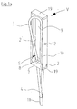
- Fig. 1a shows a schematic perspective view of a first embodiment of the device V according to the invention, which is intended to be embedded in a concrete component 1 and to serve in the cured state of the concrete for striking and lifting the concrete component 1.
- the device V comprises a storage box 2 and, in the present embodiment, a flexible cable element S, which penetrates the storage box in the region of an opening 7.
- the flexible cable element S has a cable loop 3 and on the opposite side of the opening 7 and the deposit box bottom 2 'a so-called end anchor 4 in the form of two end portions of the cable element, which are interconnected at their ends by means of a steel press clamp 11 or the like.
- the flexible cable element may be, for example, a wire cable section, the present invention not being limited to this and other flexible support elements may also be used. Thanks to its flexibility, the flexible cable loop 3 can be deflected by hand relative to the storage box 2 and can also be received within a cavity formed by the storage box 2.
- Fig. 1a the flexible cable element S is shown in a relaxed, ie unloaded state, in which, apart from possible deflecting forces in the area of the passage opening 7 and the dead weight, no external forces act on the flexible cable element S. In this condition
- the cable loop 3 and the end anchor 4 of the flexible cable element S each have an angle in the range between 5 and 25 ° relative to the trolley bottom 2 'a.
- the storage box 2 is preferably made of robust sheet steel in one piece and formed as an elongated body, in the interior of the cable loop 3 can be accommodated. It has proved to be advantageous to form the storage box 2 in the longitudinal profile in C or U-shape. In the region of the opening 7 of the deposit box bottom 2 ', a molded part 8 can be provided in order to prevent the penetration or escape of concrete or sludge.
- the ends of the storage box 2 are preferably formed from bent sheet metal and folded over so that they close the storage box 2 solid as the end cover 19.
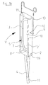
- FIG. 1b A development of the embodiment Fig. 1a is in Fig. 1b shown in a schematic perspective view.
- the embodiment in Fig. 1b additionally comprises a fastening element 13, by means of which the device can be attached to rod-shaped elements such as reinforcing bars or the like.
- the fastener 13 may be formed integrally with the storage box 2, in the present embodiment it is a separate component mounted in receptacles 12 and the side walls of the storage box 2.
- the receptacles 12 of the custody box 2 may be openings, recesses, indentations and / or deflections, which allow easy attachment and possibly also release of the fastener 13.
- the fastener 13 may take a variety of forms, but is preferably configured so that it can be easily hung on a rod-shaped element.
- Advantageous embodiments of the fastener 13 are for example a wire bending part, a sheet metal part or a plastic part, wherein it is preferred in terms of hanging that the Fastening element 13 has an at least partially curved shape.
- FIG. 1c A further embodiment of the device according to the invention is shown in a schematic perspective view in FIG Fig. 1c shown.
- device V corresponds to the embodiment of Fig. 1b , which is additionally provided with a removable cover 18 which closes an opening 9 of the storage box 2 opposite the storage box floor 2 'of the storage box 2.
- the cover 18 is preferably made of a self-adhesive film and ensures that during a concreting process no concrete or seepage penetrates into the interior of the storage box 2.
- the Fig. 1c shows the cover 18 in a partially opened state.
- the device V according to the present invention is preferably combined with at least one fastening element
- the device V or the storage box 2 can also alternatively or additionally be attached directly to a formwork section 15, as in FIG Fig. 2 shown schematically.
- the Fig. 2 shown embodiment of the device V for this purpose comprises two nail holes 17 through which nails 16 can be hammered into a formwork section 15 to attach the storage box 2 itself to this.
- the nail holes are also in Fig. 3 shown.
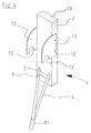
- FIG Fig. 3 and 4 Further embodiments of the device V according to the invention are shown in FIG Fig. 3 and 4 shown in schematic views.
- the embodiment in Fig. 3 is characterized in that the fastening element 13 is formed in the form of a short, curved hook made of flat material, by means of which the device V can be easily hung on a rod 14.
- the alternative embodiment according to Fig. 4 is characterized by fasteners 13 made of a flat material, which need not be bent, but in which the Einh brieflyfunktion by recesses 13 'is achieved, in which a rod-shaped element can easily engage.
- FIG Fig. 5 shown in a schematic side view.
- the cable loop 3 is located within the storage box 2, so that it does not interfere with the production of the precast concrete part 1 within the formwork sections 15.
- the collapse of the cable loop 3 in the interior of the storage box 2 can be done in any way, for example by means of a film cover, by means of lateral support elements or by simply applying the storage box 2 to the formwork section 15.
- the advantage here is that the cable loop 3 of her in Fig. 1a shown, relaxed state only slightly deflected to get into the interior of the storage box 2.
- the end anchor 4 of the flexible cable element S in the installed state has its already in Fig. 1a shown alignment and stands at an angle between 0 and 45 °, preferably between 5 and 25 ° relative to the storage box bottom 2 'on the concrete side 6.
- this flat angle of Endankers 4 even in thin or slender components has the advantage that the press clamp 11 is not applied to the opposite formwork section 15, but freely within the reinforced concrete precast element 1 comes to rest, so that with the device according to the invention V can also produce very narrow or slender components without any problems and without undesirable disturbances on the component surface or deformations of the end anchor 4.
- Fig. 6 shown schematically.
- an optionally present cover 18 is removed from the storage box 2, whereupon the cable loop 3, if it is not held by further holding elements, in the in Fig. 1 shown, relaxed state comes out of the interior of the storage box 2.
- the device V is thus already ready to hook or hang a crane hook 20. This must, as in Fig. 6 shown, now only fed and attached. In this case, the tip of the crane hook can penetrate into the interior of the storage box 2, which considerably facilitates the hooking of the crane hook 20 into the cable loop 3 and avoids sources of error.
- Fig. 6 shown schematically.
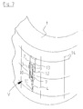
- FIG. 7 An example of a frequently encountered hollow concrete component is in Fig. 7 shown schematically.
- This is a tube section 1, in whose curved outer wall the device V according to the invention is suspended by means of a fastening element 13.
- Such tubular components 1 often have a very small wall thickness, so that the use of known stop means is usually difficult, while the device V according to the invention enables a safe and trouble-free lifting of the component 1.
- the attachment of the device in the net-like prefabricated rod-shaped reinforcement using the fastening device 13 allows the preferred use of steel formwork to which one can not nail.
Landscapes
- Engineering & Computer Science (AREA)
- Architecture (AREA)
- Mechanical Engineering (AREA)
- Civil Engineering (AREA)
- Structural Engineering (AREA)
- Load-Engaging Elements For Cranes (AREA)
- Conveying And Assembling Of Building Elements In Situ (AREA)
Claims (16)
- Dispositif (V) pour élinguer et lever des pièces en béton, en particulier des pièces préfabriquées en béton armé (1), avec un caisson de stockage (2) et au moins un élément de câble (S) flexible, traversant le caisson de stockage (2), comprenant une boucle de câble (3) et un ancrage d'extrémité (4), la boucle de câble (4) étant susceptible d'être logée au moins partiellement dans le caisson de stockage (2) et étant susceptible d'être sortie de celui-ci,
caractérisé en ce que la boucle de câble et/ou l'ancrage d'extrémité (4) du au moins un élément de câble (S) flexible, à l'état relâché ou non chargé, fait, au moins par tronçons, par rapport au fond de caisson de stockage (2') un angle (δ) entre 0 et 45°. - Dispositif selon la revendication 1, caractérisé en ce que la boucle de câble et/ou l'ancrage d'extrémité (4) du au moins un élément de câble (S) flexible, fait, au moins par tronçons, par rapport au fond de caisson de stockage (2') un angle (δ) entre 5 et 25°.
- Dispositif selon la revendication 1 ou 2, caractérisé en ce que les extrémités du au moins un élément de câble (S) sont reliées ensemble dans la zone de l'ancrage d'extrémité (4), de préférence au moyen d'une pince de pressage en acier (9).
- Dispositif selon l'une des revendications précédentes, caractérisé en ce que le caisson de stockage (2) est un corps allongé, pour recevoir la au moins une boucle de câble (3).
- Dispositif selon l'une des revendications précédentes, caractérisé en ce que le caisson de stockage (2) constitue une profil longitudinal à forme en C ou en U.
- Dispositif selon l'une des revendications précédentes, caractérisé en ce que le au moins un élément de câble (S) traverse le fond de caisson de stockage (2') dans la zone d'un passage (7) fermé de manière étanche par une pièce de forme (8).
- Dispositif selon l'une des revendications précédentes, caractérisé en ce qu'il présente en outre un élément de fixation (13), au moyen duquel le dispositif est susceptible d'être monté, en particulier est susceptible d'être accroché, sur des éléments en forme de barres, tels que des barres d'armature ou analogues.
- Dispositif selon la revendication 7, caractérisé en ce que l'élément de fixation (13) est composé d'une pièce pliée en fil métallique, d'une pièce en tôle ou d'une pièce en matière synthétique et/ou présente une forme incurvée au moins par tronçons.
- Dispositif selon l'une des revendications précédentes, caractérisé en ce qu'au moins un logement (12), en particulier une ouverture, cavité, enfoncement et/ou coude obtenu par écartement, est prévu sur le caisson de stockage (2) pour montage d'un élément de fixation (13).
- Dispositif selon l'une quelconque des revendications 7 à 9, caractérisé en ce que l'élément de fixation (13) est réalisé d'une seule pièce avec le caisson de stockage (2).
- Dispositif selon l'une des revendications précédentes, caractérisé en ce que les extrémités situés du côté frontal du caisson de stockage (2) sont fermées de manière étanche par des couvercles d'extrémité (19).
- Dispositif selon l'une quelconque des revendications précédentes, caractérisé en ce que les extrémités situés du côté frontal du caisson de stockage (2) sont obtenues d'une seule pièce par des coudages (19).
- Dispositif selon l'une quelconque des revendications précédentes, caractérisé en ce que le caisson de stockage (2) présente, sur sa face opposée au fond de caisson de stockage (2'), une ouverture (9) obturée au moyen d'un couvercle (18) amovible.
- Dispositif selon la revendication 13, caractérisé en ce que le couvercle (18) amovible est réalisé sous la forme d'une feuille autoadhésive.
- Dispositif selon l'une quelconque des revendications précédentes, caractérisé en ce que le caisson de stockage (2) présente au moins un trou pour clou (16), de préférence au moins deux trous pour clou, pour la fixation du caisson de stockage (2) sur un coffrage (15).
- Elément de construction en béton, en particulier pièce préfabriquée en béton armé (1), avec un dispositif selon l'une quelconque des revendications précédentes, caractérisé en ce que la boucle de câble (3) et/ou l'ancrage d'extrémité (4) du au moins un élément de câble (S) flexible, fait, au moins par tronçons, également par rapport à la surface d'élément de construction limitrophe, un angle (δ) entre 0 et 45°, de préférence entre 5 et 25°.
Priority Applications (1)
| Application Number | Priority Date | Filing Date | Title |
|---|---|---|---|
| PL05009689T PL1596015T3 (pl) | 2004-05-10 | 2005-05-03 | Urządzenie do unoszenia elementów betonowych |
Applications Claiming Priority (2)
| Application Number | Priority Date | Filing Date | Title |
|---|---|---|---|
| DE202004007467U DE202004007467U1 (de) | 2004-05-10 | 2004-05-10 | Vorrichtung für das Anheben von Betonteilen |
| DE202004007467U | 2004-05-10 |
Publications (2)
| Publication Number | Publication Date |
|---|---|
| EP1596015A1 EP1596015A1 (fr) | 2005-11-16 |
| EP1596015B1 true EP1596015B1 (fr) | 2011-07-20 |
Family
ID=32695504
Family Applications (1)
| Application Number | Title | Priority Date | Filing Date |
|---|---|---|---|
| EP05009689A Expired - Lifetime EP1596015B1 (fr) | 2004-05-10 | 2005-05-03 | Dispositif pour élever des pièces en béton |
Country Status (7)
| Country | Link |
|---|---|
| US (1) | US7395635B2 (fr) |
| EP (1) | EP1596015B1 (fr) |
| AT (1) | ATE517215T1 (fr) |
| DE (1) | DE202004007467U1 (fr) |
| DK (1) | DK1596015T3 (fr) |
| ES (1) | ES2369506T3 (fr) |
| PL (1) | PL1596015T3 (fr) |
Families Citing this family (18)
| Publication number | Priority date | Publication date | Assignee | Title |
|---|---|---|---|---|
| DE502004005369D1 (de) * | 2004-09-17 | 2007-12-13 | Halfen Gmbh | Seilschlaufenanordnung |
| ES2299378B1 (es) * | 2006-11-03 | 2009-11-11 | Juan Casas Alvarez | Metodo de sujecion para estructuras de hormigon armado o similar y elemento de sujecion aplicable a dicho metodo. |
| WO2008053061A1 (fr) * | 2006-11-03 | 2008-05-08 | Juan Casas Alvarez | Procédé de fixation de structures en béton armé ou analogue et élément de fixation utilisé dans ledit procédé |
| US20090199504A1 (en) * | 2008-02-07 | 2009-08-13 | Tomarco Contractor Specialties, Inc. | Support structure for use with metal beams |
| ES2339204B1 (es) * | 2008-02-08 | 2011-05-10 | Juan Casas Alvarez | Sistema de anclaje para estructuras de hormigon y similar. |
| USD633417S1 (en) * | 2008-05-02 | 2011-03-01 | Donna Medved | Unitary towing hook |
| NZ590193A (en) * | 2008-06-13 | 2013-02-22 | Bluescope Steel Ltd | Tilt slab concrete wall with elongate structural sheet metal members in vertical and transverse directions connected to sheet metal decking sheets and with edge channels adapted to nest adjacent wall panels |
| US20100084540A1 (en) * | 2008-09-23 | 2010-04-08 | Nick Talley | Pocket Forming Insert |
| AU2009230822B2 (en) * | 2008-12-02 | 2016-05-12 | Illinois Tool Works Inc. | An anchor for lifting a concrete component |
| DE502009000173D1 (de) * | 2009-03-12 | 2010-12-23 | Gerhard Krummel | Vorrichtung zum Verbund von Fertigbetonteilen |
| DE202009004065U1 (de) * | 2009-03-26 | 2009-11-05 | Pfeifer Holding Gmbh & Co. Kg | Lastaufnahmemittel |
| FR2959764B1 (fr) * | 2010-05-07 | 2012-05-18 | Rector Lesage | Mur a coffrage integre equipe d'au moins un organe de levage et procede de fabrication d'un tel mur |
| US8511038B2 (en) * | 2011-02-15 | 2013-08-20 | Randel Brandstrom | Concrete panel with fiber reinforced rebar |
| US8978343B1 (en) * | 2014-07-18 | 2015-03-17 | Frederick J Sandor | Method and system for transporting a cast panel |
| US9890545B1 (en) * | 2016-11-14 | 2018-02-13 | Steven James Bongiorno | Erection system |
| DE202018102682U1 (de) * | 2018-05-14 | 2019-08-19 | Philipp Gmbh | Vorrichtung zur Positionierung eines Transportankers |
| CN109624057A (zh) * | 2018-12-21 | 2019-04-16 | 海盐宏拓五金有限公司 | 一种混凝土预制钢丝绳铁盒 |
| FI129715B (en) * | 2019-07-08 | 2022-07-29 | R Group Baltic Oue | Wire link box |
Family Cites Families (14)
| Publication number | Priority date | Publication date | Assignee | Title |
|---|---|---|---|---|
| US4304431A (en) | 1980-03-24 | 1981-12-08 | Walston Everett V | Handling/lifter device for a concrete slab or the like |
| US4443980A (en) * | 1981-03-19 | 1984-04-24 | Pennsylvania Insert Corporation | Pulling iron enclosure |
| DE3127087C2 (de) | 1981-07-09 | 1986-04-10 | Sigma Bauelemente Gmbh, 4800 Bielefeld | Vorrichtung zum Verwahren von Bewehrungsstählen |
| DE3541262A1 (de) | 1984-11-30 | 1986-06-05 | Haeussler, Ernst, Dr.-Ing., 4300 Essen | Vorrichtung zum anhaengen eines betonfertigteils an ein hebezeug |
| DE4109706C2 (de) | 1990-05-17 | 1994-06-30 | Frank Gmbh & Co Kg Max | Betoneinbauelement |
| DE69232347T2 (de) | 1991-09-27 | 2002-07-11 | Canon K.K., Tokio/Tokyo | Verfahren zur Behandlung eines Substrats aus Silizium |
| DE9216428U1 (de) | 1992-12-02 | 1993-05-19 | Breul, Frank, 6419 Burghaun | Verwahrungselement |
| DE29505789U1 (de) | 1995-04-04 | 1996-08-01 | BETOMAX Kunststoff- und Metallwarenfabrik GmbH & Co KG, 41460 Neuss | Vorrichtung zum Verwahren mindestens einer elastisch verformbaren Halterung |
| DE29513732U1 (de) | 1995-08-26 | 1995-10-26 | Pfeifer Seil- und Hebetechnik GmbH & Co, 87700 Memmingen | Vorrichtung zum Verbinden eines Betonfertigteiles mit dem Lasttragmittel eines Hebezeugs |
| DE29612573U1 (de) | 1996-07-20 | 1997-11-20 | Pfeifer Seil- und Hebetechnik GmbH & Co, 87700 Memmingen | Vorrichtung zum Verbund von Betonfertigteilen |
| AUPP592598A0 (en) * | 1998-09-16 | 1998-10-08 | Ramset Fasteners (Aust.) Pty. Limited | Cast-in fittings for concrete components |
| US6431508B1 (en) * | 2000-11-06 | 2002-08-13 | The United States Of America As Represented By The Secretary Of The Navy | Adaptable and universal system for attachments |
| US6688049B2 (en) | 2002-01-31 | 2004-02-10 | Bowco Industries Inc. | Hook facility for concrete structure |
| US7137609B2 (en) * | 2003-01-09 | 2006-11-21 | Pennsylvania Insert Corp. | Pulling iron pocket, lid and shield |
-
2004
- 2004-05-10 DE DE202004007467U patent/DE202004007467U1/de not_active Expired - Lifetime
- 2004-06-28 US US10/879,342 patent/US7395635B2/en not_active Expired - Lifetime
-
2005
- 2005-05-03 PL PL05009689T patent/PL1596015T3/pl unknown
- 2005-05-03 EP EP05009689A patent/EP1596015B1/fr not_active Expired - Lifetime
- 2005-05-03 DK DK05009689.0T patent/DK1596015T3/da active
- 2005-05-03 AT AT05009689T patent/ATE517215T1/de active
- 2005-05-03 ES ES05009689T patent/ES2369506T3/es not_active Expired - Lifetime
Also Published As
| Publication number | Publication date |
|---|---|
| ES2369506T3 (es) | 2011-12-01 |
| DK1596015T3 (da) | 2011-10-24 |
| DE202004007467U1 (de) | 2004-07-08 |
| US20050257445A1 (en) | 2005-11-24 |
| US7395635B2 (en) | 2008-07-08 |
| ATE517215T1 (de) | 2011-08-15 |
| EP1596015A1 (fr) | 2005-11-16 |
| PL1596015T3 (pl) | 2011-11-30 |
Similar Documents
| Publication | Publication Date | Title |
|---|---|---|
| EP1596015B1 (fr) | Dispositif pour élever des pièces en béton | |
| WO2014012681A1 (fr) | Système d'ancrage fixable pour coffrage de mur et procédé | |
| EP2376617B1 (fr) | Paroi de contenant pour un contenant couvert d'une feuille et coffrage extérieur pour la fabrication de la paroi de contenant | |
| EP3029220A1 (fr) | Système à ancrage de transport de doubles parois préfabriquées béton/acier | |
| EP0819203B2 (fr) | Dispositif de maintien d'au moins un element de fixation elastiquement deformable et procede de betonnage par section utilisant de tels elements de fixation comme jonction de betonnage | |
| DE102011088456B4 (de) | Anordnung mit Positionierungselement zum Positionieren zumindest eines stabförmigen Bewehrungselementes | |
| EP3795777B1 (fr) | Dispositif de décoffrage pour une ouverture murale | |
| DE3121249C2 (de) | Verankerung für Steigeisen in Teilen aus Beton o.dgl. | |
| DE29906417U1 (de) | Vorrichtung zum Verwahren mindestens einer elastisch verformbaren Seilschlaufe in der Oberfläche von Betonfertigteile | |
| EP1101883B1 (fr) | Procédé pour la réalisation d'un raccordement d'armatures entre un élément de construction en béton et un élément de construction connecté | |
| EP3032002A1 (fr) | Console grimpante et son element de coffrage | |
| DE202010007650U1 (de) | Schalungselement | |
| DE3732180C2 (fr) | ||
| DE102010017046A1 (de) | Vorrichtung zum Verbinden von zwei durch eine Fuge getrennte Bauteile und zur Aufnahme von zwischen den Bauteilen auftretenden Querkräften | |
| LU84389A1 (de) | Verankerungsvorrichtung fuer pfaehle oder dgl. | |
| DE19517233C2 (de) | Vermarkungseinrichtung zur Befestigung von Vermessungspunkten | |
| DE102017111473A1 (de) | Transportankersystem mit Abstandhalter | |
| EP2096223B1 (fr) | Dispositif de positionnement et d'ancrage à position et angle précis d'une barre de tension | |
| DE4234701C2 (de) | Verbindungsteil | |
| EP1557499B1 (fr) | Dispositif pour accrochage d'un revetement d'un batiment | |
| EP1672142B1 (fr) | Élément d'ancrage pour coffrage de bord du plafond | |
| DE2403790A1 (de) | Vorrichtung zum aussteifen einer bauverschalung | |
| WO2009147042A1 (fr) | Coffret pour boucle de câble | |
| EP3693521A1 (fr) | Tourillon de montage pour dispositif d'ancrage et procédé d'extension de tourillon de montage | |
| DE6601068U (de) | Transport-verankerung fuer beton-fertigbauteile |
Legal Events
| Date | Code | Title | Description |
|---|---|---|---|
| PUAI | Public reference made under article 153(3) epc to a published international application that has entered the european phase |
Free format text: ORIGINAL CODE: 0009012 |
|
| AK | Designated contracting states |
Kind code of ref document: A1 Designated state(s): AT BE BG CH CY CZ DE DK EE ES FI FR GB GR HU IE IS IT LI LT LU MC NL PL PT RO SE SI SK TR |
|
| AX | Request for extension of the european patent |
Extension state: AL BA HR LV MK YU |
|
| 17P | Request for examination filed |
Effective date: 20051219 |
|
| AKX | Designation fees paid |
Designated state(s): AT BE BG CH CY CZ DE DK EE ES FI FR GB GR HU IE IS IT LI LT LU MC NL PL PT RO SE SI SK TR |
|
| GRAP | Despatch of communication of intention to grant a patent |
Free format text: ORIGINAL CODE: EPIDOSNIGR1 |
|
| GRAS | Grant fee paid |
Free format text: ORIGINAL CODE: EPIDOSNIGR3 |
|
| GRAA | (expected) grant |
Free format text: ORIGINAL CODE: 0009210 |
|
| AK | Designated contracting states |
Kind code of ref document: B1 Designated state(s): AT BE BG CH CY CZ DE DK EE ES FI FR GB GR HU IE IS IT LI LT LU MC NL PL PT RO SE SI SK TR |
|
| REG | Reference to a national code |
Ref country code: GB Ref legal event code: FG4D Free format text: NOT ENGLISH |
|
| REG | Reference to a national code |
Ref country code: CH Ref legal event code: EP Ref country code: CH Ref legal event code: NV Representative=s name: NOVAGRAAF INTERNATIONAL SA |
|
| REG | Reference to a national code |
Ref country code: DE Ref legal event code: R096 Ref document number: 502005011627 Country of ref document: DE Effective date: 20110908 |
|
| REG | Reference to a national code |
Ref country code: RO Ref legal event code: EPE |
|
| REG | Reference to a national code |
Ref country code: DK Ref legal event code: T3 |
|
| REG | Reference to a national code |
Ref country code: NL Ref legal event code: VDEP Effective date: 20110720 |
|
| REG | Reference to a national code |
Ref country code: PL Ref legal event code: T3 |
|
| REG | Reference to a national code |
Ref country code: ES Ref legal event code: FG2A Ref document number: 2369506 Country of ref document: ES Kind code of ref document: T3 Effective date: 20111201 |
|
| PG25 | Lapsed in a contracting state [announced via postgrant information from national office to epo] |
Ref country code: IS Free format text: LAPSE BECAUSE OF FAILURE TO SUBMIT A TRANSLATION OF THE DESCRIPTION OR TO PAY THE FEE WITHIN THE PRESCRIBED TIME-LIMIT Effective date: 20111120 Ref country code: PT Free format text: LAPSE BECAUSE OF FAILURE TO SUBMIT A TRANSLATION OF THE DESCRIPTION OR TO PAY THE FEE WITHIN THE PRESCRIBED TIME-LIMIT Effective date: 20111121 Ref country code: NL Free format text: LAPSE BECAUSE OF FAILURE TO SUBMIT A TRANSLATION OF THE DESCRIPTION OR TO PAY THE FEE WITHIN THE PRESCRIBED TIME-LIMIT Effective date: 20110720 Ref country code: LT Free format text: LAPSE BECAUSE OF FAILURE TO SUBMIT A TRANSLATION OF THE DESCRIPTION OR TO PAY THE FEE WITHIN THE PRESCRIBED TIME-LIMIT Effective date: 20110720 Ref country code: SE Free format text: LAPSE BECAUSE OF FAILURE TO SUBMIT A TRANSLATION OF THE DESCRIPTION OR TO PAY THE FEE WITHIN THE PRESCRIBED TIME-LIMIT Effective date: 20110720 |
|
| REG | Reference to a national code |
Ref country code: IE Ref legal event code: FD4D |
|
| PG25 | Lapsed in a contracting state [announced via postgrant information from national office to epo] |
Ref country code: SI Free format text: LAPSE BECAUSE OF FAILURE TO SUBMIT A TRANSLATION OF THE DESCRIPTION OR TO PAY THE FEE WITHIN THE PRESCRIBED TIME-LIMIT Effective date: 20110720 Ref country code: GR Free format text: LAPSE BECAUSE OF FAILURE TO SUBMIT A TRANSLATION OF THE DESCRIPTION OR TO PAY THE FEE WITHIN THE PRESCRIBED TIME-LIMIT Effective date: 20111021 Ref country code: CY Free format text: LAPSE BECAUSE OF FAILURE TO SUBMIT A TRANSLATION OF THE DESCRIPTION OR TO PAY THE FEE WITHIN THE PRESCRIBED TIME-LIMIT Effective date: 20110720 |
|
| PG25 | Lapsed in a contracting state [announced via postgrant information from national office to epo] |
Ref country code: SK Free format text: LAPSE BECAUSE OF FAILURE TO SUBMIT A TRANSLATION OF THE DESCRIPTION OR TO PAY THE FEE WITHIN THE PRESCRIBED TIME-LIMIT Effective date: 20110720 Ref country code: IE Free format text: LAPSE BECAUSE OF FAILURE TO SUBMIT A TRANSLATION OF THE DESCRIPTION OR TO PAY THE FEE WITHIN THE PRESCRIBED TIME-LIMIT Effective date: 20110720 |
|
| REG | Reference to a national code |
Ref country code: HU Ref legal event code: AG4A Ref document number: E012601 Country of ref document: HU |
|
| PLBE | No opposition filed within time limit |
Free format text: ORIGINAL CODE: 0009261 |
|
| STAA | Information on the status of an ep patent application or granted ep patent |
Free format text: STATUS: NO OPPOSITION FILED WITHIN TIME LIMIT |
|
| PG25 | Lapsed in a contracting state [announced via postgrant information from national office to epo] |
Ref country code: IT Free format text: LAPSE BECAUSE OF FAILURE TO SUBMIT A TRANSLATION OF THE DESCRIPTION OR TO PAY THE FEE WITHIN THE PRESCRIBED TIME-LIMIT Effective date: 20110720 Ref country code: EE Free format text: LAPSE BECAUSE OF FAILURE TO SUBMIT A TRANSLATION OF THE DESCRIPTION OR TO PAY THE FEE WITHIN THE PRESCRIBED TIME-LIMIT Effective date: 20110720 |
|
| 26N | No opposition filed |
Effective date: 20120423 |
|
| REG | Reference to a national code |
Ref country code: DE Ref legal event code: R097 Ref document number: 502005011627 Country of ref document: DE Effective date: 20120423 |
|
| PG25 | Lapsed in a contracting state [announced via postgrant information from national office to epo] |
Ref country code: MC Free format text: LAPSE BECAUSE OF NON-PAYMENT OF DUE FEES Effective date: 20120531 |
|
| PG25 | Lapsed in a contracting state [announced via postgrant information from national office to epo] |
Ref country code: BG Free format text: LAPSE BECAUSE OF FAILURE TO SUBMIT A TRANSLATION OF THE DESCRIPTION OR TO PAY THE FEE WITHIN THE PRESCRIBED TIME-LIMIT Effective date: 20111020 |
|
| PG25 | Lapsed in a contracting state [announced via postgrant information from national office to epo] |
Ref country code: TR Free format text: LAPSE BECAUSE OF FAILURE TO SUBMIT A TRANSLATION OF THE DESCRIPTION OR TO PAY THE FEE WITHIN THE PRESCRIBED TIME-LIMIT Effective date: 20110720 |
|
| PG25 | Lapsed in a contracting state [announced via postgrant information from national office to epo] |
Ref country code: LU Free format text: LAPSE BECAUSE OF NON-PAYMENT OF DUE FEES Effective date: 20120503 |
|
| REG | Reference to a national code |
Ref country code: FR Ref legal event code: PLFP Year of fee payment: 12 |
|
| REG | Reference to a national code |
Ref country code: FR Ref legal event code: PLFP Year of fee payment: 13 |
|
| REG | Reference to a national code |
Ref country code: FR Ref legal event code: PLFP Year of fee payment: 14 |
|
| PGFP | Annual fee paid to national office [announced via postgrant information from national office to epo] |
Ref country code: FR Payment date: 20210521 Year of fee payment: 17 Ref country code: CZ Payment date: 20210421 Year of fee payment: 17 Ref country code: RO Payment date: 20210427 Year of fee payment: 17 |
|
| PGFP | Annual fee paid to national office [announced via postgrant information from national office to epo] |
Ref country code: CH Payment date: 20210525 Year of fee payment: 17 Ref country code: ES Payment date: 20210618 Year of fee payment: 17 Ref country code: GB Payment date: 20210526 Year of fee payment: 17 Ref country code: BE Payment date: 20210519 Year of fee payment: 17 Ref country code: AT Payment date: 20210518 Year of fee payment: 17 |
|
| REG | Reference to a national code |
Ref country code: CH Ref legal event code: PL |
|
| REG | Reference to a national code |
Ref country code: AT Ref legal event code: MM01 Ref document number: 517215 Country of ref document: AT Kind code of ref document: T Effective date: 20220503 |
|
| REG | Reference to a national code |
Ref country code: BE Ref legal event code: MM Effective date: 20220531 |
|
| GBPC | Gb: european patent ceased through non-payment of renewal fee |
Effective date: 20220503 |
|
| PG25 | Lapsed in a contracting state [announced via postgrant information from national office to epo] |
Ref country code: RO Free format text: LAPSE BECAUSE OF NON-PAYMENT OF DUE FEES Effective date: 20220503 Ref country code: LI Free format text: LAPSE BECAUSE OF NON-PAYMENT OF DUE FEES Effective date: 20220531 Ref country code: CZ Free format text: LAPSE BECAUSE OF NON-PAYMENT OF DUE FEES Effective date: 20220503 Ref country code: CH Free format text: LAPSE BECAUSE OF NON-PAYMENT OF DUE FEES Effective date: 20220531 Ref country code: AT Free format text: LAPSE BECAUSE OF NON-PAYMENT OF DUE FEES Effective date: 20220503 |
|
| PG25 | Lapsed in a contracting state [announced via postgrant information from national office to epo] |
Ref country code: FR Free format text: LAPSE BECAUSE OF NON-PAYMENT OF DUE FEES Effective date: 20220531 |
|
| PG25 | Lapsed in a contracting state [announced via postgrant information from national office to epo] |
Ref country code: GB Free format text: LAPSE BECAUSE OF NON-PAYMENT OF DUE FEES Effective date: 20220503 Ref country code: BE Free format text: LAPSE BECAUSE OF NON-PAYMENT OF DUE FEES Effective date: 20220531 |
|
| REG | Reference to a national code |
Ref country code: ES Ref legal event code: FD2A Effective date: 20230626 |
|
| P01 | Opt-out of the competence of the unified patent court (upc) registered |
Effective date: 20230525 |
|
| PG25 | Lapsed in a contracting state [announced via postgrant information from national office to epo] |
Ref country code: ES Free format text: LAPSE BECAUSE OF NON-PAYMENT OF DUE FEES Effective date: 20220504 |
|
| PGFP | Annual fee paid to national office [announced via postgrant information from national office to epo] |
Ref country code: DK Payment date: 20230511 Year of fee payment: 19 Ref country code: DE Payment date: 20230508 Year of fee payment: 19 |
|
| PGFP | Annual fee paid to national office [announced via postgrant information from national office to epo] |
Ref country code: PL Payment date: 20230424 Year of fee payment: 19 Ref country code: HU Payment date: 20230417 Year of fee payment: 19 Ref country code: FI Payment date: 20230510 Year of fee payment: 19 |
|
| REG | Reference to a national code |
Ref country code: DE Ref legal event code: R119 Ref document number: 502005011627 Country of ref document: DE |
|
| REG | Reference to a national code |
Ref country code: DK Ref legal event code: EBP Effective date: 20240531 |
|
| PG25 | Lapsed in a contracting state [announced via postgrant information from national office to epo] |
Ref country code: FI Free format text: LAPSE BECAUSE OF NON-PAYMENT OF DUE FEES Effective date: 20240503 |
|
| PG25 | Lapsed in a contracting state [announced via postgrant information from national office to epo] |
Ref country code: FI Free format text: LAPSE BECAUSE OF NON-PAYMENT OF DUE FEES Effective date: 20240503 |
|
| PG25 | Lapsed in a contracting state [announced via postgrant information from national office to epo] |
Ref country code: HU Free format text: LAPSE BECAUSE OF NON-PAYMENT OF DUE FEES Effective date: 20240504 |
|
| PG25 | Lapsed in a contracting state [announced via postgrant information from national office to epo] |
Ref country code: DE Free format text: LAPSE BECAUSE OF NON-PAYMENT OF DUE FEES Effective date: 20241203 |
|
| PG25 | Lapsed in a contracting state [announced via postgrant information from national office to epo] |
Ref country code: DK Free format text: LAPSE BECAUSE OF NON-PAYMENT OF DUE FEES Effective date: 20240531 |
|
| PG25 | Lapsed in a contracting state [announced via postgrant information from national office to epo] |
Ref country code: PL Free format text: LAPSE BECAUSE OF NON-PAYMENT OF DUE FEES Effective date: 20240503 |