EP1596021A2 - Wandelement mit Lehm- oder Tonschicht - Google Patents
Wandelement mit Lehm- oder Tonschicht Download PDFInfo
- Publication number
- EP1596021A2 EP1596021A2 EP05010580A EP05010580A EP1596021A2 EP 1596021 A2 EP1596021 A2 EP 1596021A2 EP 05010580 A EP05010580 A EP 05010580A EP 05010580 A EP05010580 A EP 05010580A EP 1596021 A2 EP1596021 A2 EP 1596021A2
- Authority
- EP
- European Patent Office
- Prior art keywords
- clay
- wall element
- element according
- formwork
- layer
- Prior art date
- Legal status (The legal status is an assumption and is not a legal conclusion. Google has not performed a legal analysis and makes no representation as to the accuracy of the status listed.)
- Granted
Links
- 239000004927 clay Substances 0.000 title claims abstract description 71
- 239000006260 foam Substances 0.000 claims abstract description 8
- 239000002131 composite material Substances 0.000 claims abstract description 5
- 238000009415 formwork Methods 0.000 claims description 26
- 238000009416 shuttering Methods 0.000 claims description 9
- 238000010276 construction Methods 0.000 claims description 5
- 239000002184 metal Substances 0.000 claims description 4
- 239000000654 additive Substances 0.000 claims description 3
- 230000000996 additive effect Effects 0.000 claims description 3
- 235000019353 potassium silicate Nutrition 0.000 claims description 2
- 239000005871 repellent Substances 0.000 claims description 2
- NTHWMYGWWRZVTN-UHFFFAOYSA-N sodium silicate Chemical compound [Na+].[Na+].[O-][Si]([O-])=O NTHWMYGWWRZVTN-UHFFFAOYSA-N 0.000 claims description 2
- 230000000855 fungicidal effect Effects 0.000 claims 1
- 230000000749 insecticidal effect Effects 0.000 claims 1
- 238000009413 insulation Methods 0.000 description 5
- 230000008901 benefit Effects 0.000 description 4
- 238000011161 development Methods 0.000 description 4
- 230000018109 developmental process Effects 0.000 description 4
- 230000002787 reinforcement Effects 0.000 description 3
- 230000004888 barrier function Effects 0.000 description 2
- 239000012530 fluid Substances 0.000 description 2
- 239000003292 glue Substances 0.000 description 2
- 238000004519 manufacturing process Methods 0.000 description 2
- 239000011505 plaster Substances 0.000 description 2
- 230000003068 static effect Effects 0.000 description 2
- 230000015572 biosynthetic process Effects 0.000 description 1
- 239000000919 ceramic Substances 0.000 description 1
- 238000013016 damping Methods 0.000 description 1
- 238000006073 displacement reaction Methods 0.000 description 1
- 230000000694 effects Effects 0.000 description 1
- 230000007613 environmental effect Effects 0.000 description 1
- 239000003344 environmental pollutant Substances 0.000 description 1
- 239000006261 foam material Substances 0.000 description 1
- 239000000417 fungicide Substances 0.000 description 1
- 230000005484 gravity Effects 0.000 description 1
- 239000002917 insecticide Substances 0.000 description 1
- 238000009434 installation Methods 0.000 description 1
- 239000000463 material Substances 0.000 description 1
- 238000000034 method Methods 0.000 description 1
- 238000005192 partition Methods 0.000 description 1
- 231100000719 pollutant Toxicity 0.000 description 1
- 239000004575 stone Substances 0.000 description 1
- 239000010902 straw Substances 0.000 description 1
- XLYOFNOQVPJJNP-UHFFFAOYSA-N water Substances O XLYOFNOQVPJJNP-UHFFFAOYSA-N 0.000 description 1
Images

Classifications
-
- E—FIXED CONSTRUCTIONS
- E04—BUILDING
- E04B—GENERAL BUILDING CONSTRUCTIONS; WALLS, e.g. PARTITIONS; ROOFS; FLOORS; CEILINGS; INSULATION OR OTHER PROTECTION OF BUILDINGS
- E04B2/00—Walls, e.g. partitions, for buildings; Wall construction with regard to insulation; Connections specially adapted to walls
- E04B2/84—Walls made by casting, pouring, or tamping in situ
- E04B2/86—Walls made by casting, pouring, or tamping in situ made in permanent forms
- E04B2/8635—Walls made by casting, pouring, or tamping in situ made in permanent forms with ties attached to the inner faces of the forms
Definitions
- the invention relates to a wall or Shuttering element with a loam or clay layer.
- the Wall element is therefore provided on the one hand as a wall, for the wall element can also be used as a formwork element, used for example for the shell concrete construction become.
- a heat-insulating shuttering element is made in particular DE 3405736 A1 known with hard foam layers.
- DE 201 20 365 describes a Formwork stone wall with loam and straw filling.
- DE 4 215 081 a clay construction wall element with a Carrier and a filling made of lightweight clay known.
- the invention is based on the object, an alternative Wall element using a shuttering element to create. Furthermore, the wall element for a good Ensuring room climate, easy to manufacture and both in terms of manufacture as well as use be environmentally friendly. Of particular advantage is that the wall made with the shuttering element an extremely good heat and sound insulation has.
- a formwork or wall element comprising at least two sheets, which comprises at least one layer containing clay or clay, which is connected to another layer by means of connecting elements.
- the wall element according to the invention is provided either as a formwork element for walls in Mantelbetonbauweise. For interior walls, it can also be used directly as a wall element, for example for partitions.
- the wall element is formed by two plates, so it may be an example prefabricated wall section.
- the wall element preferably on the inside of the wall on a clay or clay-containing layer. This layer can also be part of a layer composite.
- the clay or clay-containing layer is preferably formed as a plate and connected via connecting elements with another layer.
- the clay or clay layer has the advantage that it can absorb high levels of moisture. As a result, the humidity in a room is kept relatively constant. In addition, clay is suitable to absorb pollutants from the air. Also, clay has huge environmental benefits. It can be dried in the air, which causes no CO 2 emissions. The particular soundproofing effects are achieved in the clay not only by its relatively high specific gravity, but also by its soft damping structure, which reduces vibrations of the wall.
- a continuous Cavity arranged between the layers or two composite layers.
- the continuous Cavity for example, be filled with concrete, thereby can previously also fluid-carrying lines in the continuous cavity can be introduced by means of the filled concrete layer can be tempered.
- the continuous cavity extend before assembly only the holding elements.
- a Reinforcement which together with concrete one forming a static supporting construction layer.
- the wall element at least on one side a Heat insulating layer, in particular a Rigid foam layer. So it is possible a combined Wall element made of a lightweight wall, for example NEOPOR, which has particularly good thermal insulation capabilities, and to provide a sound insulating clay layer.
- the Clay or clay-containing layer part of a multiple Layers comprehensive layer composite is the Clay or clay-containing layer part of a multiple Layers comprehensive layer composite.
- a combined Hartschaumlehm für be provided can so on one side of the wall a combined Hartschaumlehm für be provided, both heat-insulating as well as sound-insulating properties has.
- Especially on the inside of the wall offers Get a clay layer.
- On the outside of the wall can For example, be provided a clay layer, the additionally with a layer of a weather resistant Material, for example, provided with a plaster layer is.
- the layers glued together have particular advantage
- waterglass proved to be present at the same time particularly advantageous as an additive of loam or clay containing layer can be added, causing these Layer of water-repellent insecticides and fungicides Gets properties and is weather resistant.
- the clay or clay layer has a clay relationship Sound content of at least 50%, even better over 70% and has particularly sound-insulating properties the layer with a clay or clay content of over 90% on. It has turned out that already one Proportion of 50% is sufficient to adequate to achieve soundproofing properties.
- the wall element for securing the grooves and springs In a further development of the invention, the wall element for securing the grooves and springs. About these grooves and springs, the wall element according to the invention in its Location, for example, secured to other wall elements become. The wall elements can be plugged into each other become.
- the clay or clay-containing layer has a thickness of at least 2 cm. It turned out that at lower layer thicknesses the sound-absorbing Properties are only unsatisfactory. For layer thicknesses over 5 cm meets the wall element in terms of Sound insulation the requirement according to DIN 4109.
- the sides of the Wall element on the inside latching points for receiving the Holding elements can then turn Have contact surfaces that as a counterpart to these Snap-in points are formed. So it is possible the Wall elements according to the invention easily fauxzustecken. In particular, by the holding elements a continuous Cavity are formed.
- connecting elements are webs, especially around metal bars.
- metal bars or wires are particularly inexpensive, moreover the webs can also be part of a reinforcement, in particular when the wall element as a formwork element is trained.
- bridges are made of concrete intended.
- the wall element as a formwork element formed, forms after filling the continuous cavity a monolithic layer, ie a base layer that consists only of concrete.
- a monolithic layer ie a base layer that consists only of concrete.
- the webs by means of a Plug connection with a layer connectable.
- Connector can, for example, a T-cross or a hook may be provided.
- the clay or Clay-containing layer of fired clay respectively burned clay on. So the clay or clay layer a get ceramic structure and is special with it insensitive to weathering, in particular offers the Use of such a layer in the wet area.
- the invention is in the as Formwork element formed wall element of the continuous Cavity filled with concrete and has approximately central tubes or continuous hollow chambers. For example, you can before filling the cavity wooden slats in the cavity are introduced before the setting of the concrete be pulled out. So remained from above below continuously extending hollow chambers, the Performing a fluid, which in turn, the formation a temperature barrier allows.
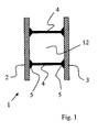
- Fig. 1 shows a schematic sectional view of a Shuttering element 1 according to the invention, in particular can also be used as a sound-absorbing interior wall can.
- the wall element 1 has an outer side 2 and a Inside 3 on. In this embodiment are both outside 2 and inside 3 of a Clay layer, each formed from a clay plate, shaped. Further layers are not provided.
- the Retaining elements 4 are formed as webs and have on the edge contact surfaces 5, which are configured so that they are the counterpart of a detent (not to see) in the clay layers 2, 3 form. Alternatively it is provided, the contact surfaces 5 to the clay layers glue. Between the two layers 2, 3 is a through-going cavity 12 is provided, through which only the holding elements 4 extend.
- the continuous cavity 12 can be carried out with cables after installation a fluid (not seen), for example, from air or from water, and then with concrete be filled.
- a fluid for example, from air or from water
- the wall element according to the invention can be tempered.
- those with concrete filled layer serve as a temperature barrier.
- the filled with concrete layer forms the additionally with a reinforcement (not visible) can be provided, a static-bearing layer of Wall.
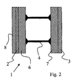
- Fig. 2 also shows a schematic sectional view a wall element according to the invention, designed here as outer wall.
- a wall element designed here as outer wall.
- clay layers 2, 3 on indoor and Outside are two insulating layers 6, 7 of one Hard foam material provided.
- On the inside forms the clay layer 3 the completion of the wall, while on the Outside a plaster layer 8 is additionally provided.
- a plaster layer 8 is additionally provided.
- At the hard foam layers 6, 7 are outdoor and Inside connected via retaining elements 4.
- Fig. 3 shows a schematic perspective view a wall element 1 according to the invention, designed as Shuttering element.
- a clay layer 2 intended.
- This clay layer 2 is via retaining elements 4, which are designed here as metal webs, with a Layer of NEOPOR 3 connected, so through the webs a Cavity 12 is formed.
- the clay layer 2 is from a formed pressed clay plate.
- the wall element 1 and has grooves 10 and springs 9, over which the individual Wall elements can be stacked on each other and so on secured against displacement.
- the hard foam layer 3 consists of a structure with cavities 11.
- the Embodiment is designed as a formwork element, its continuous cavity 12, for example, with concrete is filled. Furthermore, it is provided, the continuous Cavity 12 before filling with concrete with fluid-leading To provide lines. So can the backfilled through Cavity 12 also serve the room temperature.
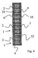
- Fig. 4 shows a plan view of an embodiment a wall element according to the invention, also designed as a formwork element.
- the wall element has two clay layers 2, 3, which are also pressed Clay plates are formed.
- the grooves 10 and 9 springs secured against slipping against each other.
- the Clay layers or clay plates 2, 3 are over plug-in holding elements 4 connected to each other.
- the clay plates on the inside a Structuring on that of a better connection with the Concrete after filling serves.
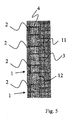
- Fig. 5 also shows a plan view of a Wall element according to the invention also formed here as formwork element, in particular for an outer wall.
- the individual wall elements 1 as in Fig. 4 the also via connecting webs 4 with the other Wall side are connected.
- On one wall side is one Heat insulating foam layer 3 is provided for a higher stiffness is honeycombed, so Has cavities 11. Again, both the clay plates as well as the hard foam elements on the inside structured to better contact after filling to be able to enter with the concrete.
Landscapes
- Engineering & Computer Science (AREA)
- Architecture (AREA)
- Physics & Mathematics (AREA)
- Electromagnetism (AREA)
- Civil Engineering (AREA)
- Structural Engineering (AREA)
- Building Environments (AREA)
- Filling Or Discharging Of Gas Storage Vessels (AREA)
- Forms Removed On Construction Sites Or Auxiliary Members Thereof (AREA)
- Panels For Use In Building Construction (AREA)
Abstract
Description
- Fig. 1 + 2
- zeigen schematische Schnittansichten von erfindungsgemäßen Wandelementen,
- Fig. 3
- zeigt eine schematische perspektivische Darstellung eines Ausführungsbeispiels eines erfindungsgemäßen Wandelements,
- Fig. 4 + 5
- zeigen schematische Darstellungen von weiteren Ausführungsbeispielen in der Draufsicht.
Claims (18)
- Zumindest zwei Platten umfassendes Schalungs- oder Wandelement (1), insbesondere für den Hausbau, gekennzeichnet durch zumindest eine Lehm und/oder Ton beinhaltende Schicht (2), die über Verbindungselemente (4) mit einer anderen Schicht verbunden ist.
- Schalungs- oder Wandelement nach Anspruch 1, dadurch gekennzeichnet, dass zwischen den Schichten zumindest ein durchgehender Hohlraum (12) angeordnet ist.
- Schalungs- oder Wandelement nach einem der vorhergehenden Ansprüche, dadurch gekennzeichnet, dass auf zumindest einer Seite des Wandelements eine Wärmeisolierschicht, insbesondere eine Hartschaumschicht (6,7) angeordnet ist.
- Schalungs- oder Wandelement nach einem der vorhergehenden Ansprüche, dadurch gekennzeichnet, dass die Lehm und/oder Ton beinhaltende Schicht Teil eines mehrere Schichten (8,2,6;7,3) umfassenden Schichtverbunds ist.
- Schalungs- oder Wandelement nach Anspruch 4, dadurch gekennzeichnet, dass die Schichten (8,2,6;7,3) miteinander verklebt sind.
- Schalungs- oder Wandelement nach einem der vorhergehenden Ansprüche, dadurch gekennzeichnet, dass die Lehm und/oder Ton beinhaltende Schicht einen Lehmbeziehungsweise Tonanteil von mindestens 50 %, bevorzugt über 70 %, besonders bevorzugt über 90 % aufweist.
- Schalungs- oder Wandelement nach einem der vorhergehenden Ansprüche, dadurch gekennzeichnet, dass das wandelement zur Lagesicherung Nuten (10) und Federn (9) aufweist.
- Schalungs- oder Wandelement nach einem der vorhergehenden Ansprüche, dadurch gekennzeichnet, dass die Lehm und/oder Ton beinhaltende Schicht ein wasserabweisendes, insektizides und/oder fungizides Additiv aufweist.
- Schalungs- oder Wandelement nach Anspruch 8, dadurch gekennzeichnet, dass es sich bei dem Additiv um Wasserglas handelt.
- Schalungs- oder Wandelement nach einem der vorhergehenden Ansprüche, dadurch gekennzeichnet, dass die Lehm und/oder Ton beinhaltende Schicht eine Dicke von mindestens 2 cm, bevorzugt mindestens 5 cm hat.
- Schalungs- oder Wandelement nach einem der Vorhergehenden Ansprüche, dadurch gekennzeichnet, dass die Seiten des Wandelements innenseitig Einraststellen zur Aufnahme der Halteelemente aufweisen.
- Wandelement nach einem der Vorhergehenden Ansprüche, dadurch gekennzeichnet, dass die Halteelemente (4) Anlageflächen (5) aufweisen, die als Gegenstück zu einer Einraststelle ausgebildet sind.
- Schalungs- oder Wandelement nach Anspruch 12, dadurch gekennzeichnet, dass die Halteelemente im Wesentlichen aus Beton bestehen.
- Schalungs- oder Wandelement nach einem der Ansprüche 1 bis 12, dadurch gekennzeichnet, dass es sich bei den Verbindungselementen (4) um Stege, insbesondere Metallstege oder Betonstege handelt.
- Schalungs- oder Wandelement nach Anspruch 14, dadurch gekennzeichnet, dass, die auf zumindest einer Seite mittels einer Steckverbindung mit einer Schicht verbindbar ist.
- Schalungs- oder Wandelement nach einem der vorhergehenden Ansprüche, dadurch gekennzeichnet, dass die Lehm und/oder Ton beinhaltende Schicht gebrannten Ton und/oder Lehm aufweist.
- Schalungs- oder Wandelement nach einem der vorhergehenden Ansprüche, dadurch gekennzeichnet, dass die Lehm und/oder Ton beinhaltende Schicht im wesentlichen durch eine gepresste Lehm- oder Tonplatte gebildet wird.
- Wandelement nach einem der vorhergehenden Ansprüche, dadurch gekennzeichnet, dass der durchgehende Hohlraum (12) mit Beton verfüllt ist und etwa mittig Rohre und/oder durchgehende Hohlkammern aufweist.
Applications Claiming Priority (2)
| Application Number | Priority Date | Filing Date | Title |
|---|---|---|---|
| DE202004007959U DE202004007959U1 (de) | 2004-05-14 | 2004-05-14 | Wandelement mit Lehm- oder Tonschicht |
| DE202004007959U | 2004-05-14 |
Publications (3)
| Publication Number | Publication Date |
|---|---|
| EP1596021A2 true EP1596021A2 (de) | 2005-11-16 |
| EP1596021A3 EP1596021A3 (de) | 2006-09-06 |
| EP1596021B1 EP1596021B1 (de) | 2010-04-14 |
Family
ID=34936552
Family Applications (1)
| Application Number | Title | Priority Date | Filing Date |
|---|---|---|---|
| EP05010580A Expired - Lifetime EP1596021B1 (de) | 2004-05-14 | 2005-05-17 | Wandelement mit Lehm- oder Tonschicht |
Country Status (4)
| Country | Link |
|---|---|
| EP (1) | EP1596021B1 (de) |
| AT (1) | ATE464438T1 (de) |
| DE (2) | DE202004007959U1 (de) |
| ES (1) | ES2343413T3 (de) |
Cited By (2)
| Publication number | Priority date | Publication date | Assignee | Title |
|---|---|---|---|---|
| ITUD20130019A1 (it) * | 2013-02-18 | 2014-08-19 | Friul Filiere S P A | Elemento costruttivo per la realizzazione di pareti e relativo procedimento di realizzazione |
| EP3904617A1 (de) * | 2020-04-27 | 2021-11-03 | Priedemann, Wolfgang | Lehmbaustein und lehmbausteinsystem |
Citations (3)
| Publication number | Priority date | Publication date | Assignee | Title |
|---|---|---|---|---|
| DE3405736A1 (de) | 1984-02-17 | 1985-08-22 | Ipa-Isorast International S.A., Panama | Schalungselement fuer die mantelbetonbauweise sowie waermedaemmplatte |
| DE4215081A1 (de) | 1992-05-07 | 1993-11-11 | Peter Breidenbach | Lehmbau-Wandelement und Verfahren zu seiner Herstellung |
| DE20120365U1 (de) | 2001-12-17 | 2002-04-04 | IFMW-Institut für Marime Wirtschaft, 18059 Rostock | Schalungssteinwand mit Lehm- und Strohfüllung |
Family Cites Families (4)
| Publication number | Priority date | Publication date | Assignee | Title |
|---|---|---|---|---|
| GB626355A (en) * | 1946-12-19 | 1949-07-13 | William Weatherhead | Improvements in building slabs or panels and wall structures made therefrom |
| DE3407867A1 (de) * | 1984-03-02 | 1985-09-05 | Paul Ensle Stiftung & Co KG, 7100 Heilbronn | Fertigbau-wandelement |
| DE29606867U1 (de) * | 1996-04-16 | 1996-07-25 | Reusing, Dieter, 73560 Böbingen | Wandsystem für Gebäudewände mit Schalungselementen, die variabel kombinierbar sind |
| DE10203159A1 (de) * | 2002-01-28 | 2003-07-31 | Lothar Mansfeld | Verfahren zum Anmischen eines Mörtels oder Mörtel-Leims aus Wasserglas und Feinstoff sowie Tockenbaustoff zur Nutzung dieses Verfahrens |
-
2004
- 2004-05-14 DE DE202004007959U patent/DE202004007959U1/de not_active Expired - Lifetime
-
2005
- 2005-05-17 EP EP05010580A patent/EP1596021B1/de not_active Expired - Lifetime
- 2005-05-17 DE DE502005009394T patent/DE502005009394D1/de not_active Expired - Lifetime
- 2005-05-17 AT AT05010580T patent/ATE464438T1/de active
- 2005-05-17 ES ES05010580T patent/ES2343413T3/es not_active Expired - Lifetime
Patent Citations (3)
| Publication number | Priority date | Publication date | Assignee | Title |
|---|---|---|---|---|
| DE3405736A1 (de) | 1984-02-17 | 1985-08-22 | Ipa-Isorast International S.A., Panama | Schalungselement fuer die mantelbetonbauweise sowie waermedaemmplatte |
| DE4215081A1 (de) | 1992-05-07 | 1993-11-11 | Peter Breidenbach | Lehmbau-Wandelement und Verfahren zu seiner Herstellung |
| DE20120365U1 (de) | 2001-12-17 | 2002-04-04 | IFMW-Institut für Marime Wirtschaft, 18059 Rostock | Schalungssteinwand mit Lehm- und Strohfüllung |
Cited By (3)
| Publication number | Priority date | Publication date | Assignee | Title |
|---|---|---|---|---|
| ITUD20130019A1 (it) * | 2013-02-18 | 2014-08-19 | Friul Filiere S P A | Elemento costruttivo per la realizzazione di pareti e relativo procedimento di realizzazione |
| WO2014125462A1 (en) | 2013-02-18 | 2014-08-21 | Friul Filiere S.P.A. | Constructive element to make walls and corresponding production method |
| EP3904617A1 (de) * | 2020-04-27 | 2021-11-03 | Priedemann, Wolfgang | Lehmbaustein und lehmbausteinsystem |
Also Published As
| Publication number | Publication date |
|---|---|
| DE202004007959U1 (de) | 2005-09-22 |
| DE502005009394D1 (de) | 2010-05-27 |
| ES2343413T3 (es) | 2010-07-30 |
| EP1596021B1 (de) | 2010-04-14 |
| EP1596021A3 (de) | 2006-09-06 |
| ATE464438T1 (de) | 2010-04-15 |
Similar Documents
| Publication | Publication Date | Title |
|---|---|---|
| EP2183099B2 (de) | Wandaufbau und wärmedämmplatte | |
| AT513134B1 (de) | Verkleidungselement für ein Gebäude | |
| WO1995032082A1 (de) | Holzbauelement mit holzlagen | |
| EP0001076B1 (de) | Hohlblockstein | |
| DE202009008493U1 (de) | Wandaufbau und Wärmedämmplatte | |
| EP1231329A1 (de) | Mauersteinförmiges Wärmedämmelement | |
| EP0697487B1 (de) | Wand-, Decken- oder Dachelement für Gebäude in Tafelbauart | |
| EP1596021B1 (de) | Wandelement mit Lehm- oder Tonschicht | |
| WO2013017622A1 (de) | Mehrschichtiges bauelement | |
| DE102009038320A1 (de) | Dämmplatte | |
| EP1995387B1 (de) | Holzbauelement und daraus gebildetes Wandelement | |
| DE2831252A1 (de) | Mauerstein | |
| DE102016117032A1 (de) | Deckschichtbauelement und Trockenbausystem | |
| AT13709U1 (de) | Holzbaustein als Vollholzhausbausystem | |
| DE202019104101U1 (de) | Wandmodul | |
| DE202007007670U1 (de) | Wandelement zur außenseitigen Anbindung an eine Wand | |
| EP1174552A2 (de) | Aussenwandverbundelement für Wohnungsgebäude | |
| EP0936063A2 (de) | Wärmedämmendes Verbundbauelement | |
| AT520127B1 (de) | Mauersturz mit isolationselement | |
| EP2826926A1 (de) | Baustein und Verfahren zur Herstellung eines Bausteins | |
| DE29622513U1 (de) | Wandaufbau in Holzkonstruktionsbauweise | |
| DE19707575A1 (de) | Vorgefertigtes Kelleraußenwandelement | |
| DE202006004060U1 (de) | Mauerstein mit in Dickenrichtung zweischaligem Aufbau | |
| AT5635U1 (de) | Holzbauelemente zur erstellung von wänden, decken, dächern und dergleichen | |
| EP1593792A2 (de) | Gross-Wandbauplatte |
Legal Events
| Date | Code | Title | Description |
|---|---|---|---|
| PUAI | Public reference made under article 153(3) epc to a published international application that has entered the european phase |
Free format text: ORIGINAL CODE: 0009012 |
|
| AK | Designated contracting states |
Kind code of ref document: A2 Designated state(s): AT BE BG CH CY CZ DE DK EE ES FI FR GB GR HU IE IS IT LI LT LU MC NL PL PT RO SE SI SK TR |
|
| AX | Request for extension of the european patent |
Extension state: AL BA HR LV MK YU |
|
| PUAL | Search report despatched |
Free format text: ORIGINAL CODE: 0009013 |
|
| AK | Designated contracting states |
Kind code of ref document: A3 Designated state(s): AT BE BG CH CY CZ DE DK EE ES FI FR GB GR HU IE IS IT LI LT LU MC NL PL PT RO SE SI SK TR |
|
| AX | Request for extension of the european patent |
Extension state: AL BA HR LV MK YU |
|
| 17P | Request for examination filed |
Effective date: 20070210 |
|
| AKX | Designation fees paid |
Designated state(s): AT BE BG CH CY CZ DE DK EE ES FI FR GB GR HU IE IS IT LI LT LU MC NL PL PT RO SE SI SK TR |
|
| 17Q | First examination report despatched |
Effective date: 20090128 |
|
| GRAP | Despatch of communication of intention to grant a patent |
Free format text: ORIGINAL CODE: EPIDOSNIGR1 |
|
| GRAS | Grant fee paid |
Free format text: ORIGINAL CODE: EPIDOSNIGR3 |
|
| GRAA | (expected) grant |
Free format text: ORIGINAL CODE: 0009210 |
|
| AK | Designated contracting states |
Kind code of ref document: B1 Designated state(s): AT BE BG CH CY CZ DE DK EE ES FI FR GB GR HU IE IS IT LI LT LU MC NL PL PT RO SE SI SK TR |
|
| REG | Reference to a national code |
Ref country code: GB Ref legal event code: FG4D Free format text: NOT ENGLISH |
|
| REG | Reference to a national code |
Ref country code: CH Ref legal event code: EP |
|
| REG | Reference to a national code |
Ref country code: IE Ref legal event code: FG4D Free format text: LANGUAGE OF EP DOCUMENT: GERMAN |
|
| REF | Corresponds to: |
Ref document number: 502005009394 Country of ref document: DE Date of ref document: 20100527 Kind code of ref document: P |
|
| REG | Reference to a national code |
Ref country code: CH Ref legal event code: NV Representative=s name: BOVARD AG PATENTANWAELTE |
|
| REG | Reference to a national code |
Ref country code: NL Ref legal event code: VDEP Effective date: 20100414 |
|
| REG | Reference to a national code |
Ref country code: ES Ref legal event code: FG2A Ref document number: 2343413 Country of ref document: ES Kind code of ref document: T3 |
|
| LTIE | Lt: invalidation of european patent or patent extension |
Effective date: 20100414 |
|
| PG25 | Lapsed in a contracting state [announced via postgrant information from national office to epo] |
Ref country code: SE Free format text: LAPSE BECAUSE OF FAILURE TO SUBMIT A TRANSLATION OF THE DESCRIPTION OR TO PAY THE FEE WITHIN THE PRESCRIBED TIME-LIMIT Effective date: 20100414 Ref country code: NL Free format text: LAPSE BECAUSE OF FAILURE TO SUBMIT A TRANSLATION OF THE DESCRIPTION OR TO PAY THE FEE WITHIN THE PRESCRIBED TIME-LIMIT Effective date: 20100414 Ref country code: LT Free format text: LAPSE BECAUSE OF FAILURE TO SUBMIT A TRANSLATION OF THE DESCRIPTION OR TO PAY THE FEE WITHIN THE PRESCRIBED TIME-LIMIT Effective date: 20100414 |
|
| REG | Reference to a national code |
Ref country code: IE Ref legal event code: FD4D |
|
| BERE | Be: lapsed |
Owner name: KRECKE, EDMOND DOMINIQUE Effective date: 20100531 |
|
| PG25 | Lapsed in a contracting state [announced via postgrant information from national office to epo] |
Ref country code: IS Free format text: LAPSE BECAUSE OF FAILURE TO SUBMIT A TRANSLATION OF THE DESCRIPTION OR TO PAY THE FEE WITHIN THE PRESCRIBED TIME-LIMIT Effective date: 20100814 Ref country code: FI Free format text: LAPSE BECAUSE OF FAILURE TO SUBMIT A TRANSLATION OF THE DESCRIPTION OR TO PAY THE FEE WITHIN THE PRESCRIBED TIME-LIMIT Effective date: 20100414 Ref country code: SI Free format text: LAPSE BECAUSE OF FAILURE TO SUBMIT A TRANSLATION OF THE DESCRIPTION OR TO PAY THE FEE WITHIN THE PRESCRIBED TIME-LIMIT Effective date: 20100414 |
|
| PG25 | Lapsed in a contracting state [announced via postgrant information from national office to epo] |
Ref country code: CY Free format text: LAPSE BECAUSE OF FAILURE TO SUBMIT A TRANSLATION OF THE DESCRIPTION OR TO PAY THE FEE WITHIN THE PRESCRIBED TIME-LIMIT Effective date: 20100421 Ref country code: GR Free format text: LAPSE BECAUSE OF FAILURE TO SUBMIT A TRANSLATION OF THE DESCRIPTION OR TO PAY THE FEE WITHIN THE PRESCRIBED TIME-LIMIT Effective date: 20100715 Ref country code: MC Free format text: LAPSE BECAUSE OF NON-PAYMENT OF DUE FEES Effective date: 20100531 Ref country code: PL Free format text: LAPSE BECAUSE OF FAILURE TO SUBMIT A TRANSLATION OF THE DESCRIPTION OR TO PAY THE FEE WITHIN THE PRESCRIBED TIME-LIMIT Effective date: 20100414 |
|
| PG25 | Lapsed in a contracting state [announced via postgrant information from national office to epo] |
Ref country code: EE Free format text: LAPSE BECAUSE OF FAILURE TO SUBMIT A TRANSLATION OF THE DESCRIPTION OR TO PAY THE FEE WITHIN THE PRESCRIBED TIME-LIMIT Effective date: 20100414 Ref country code: PT Free format text: LAPSE BECAUSE OF FAILURE TO SUBMIT A TRANSLATION OF THE DESCRIPTION OR TO PAY THE FEE WITHIN THE PRESCRIBED TIME-LIMIT Effective date: 20100816 Ref country code: DK Free format text: LAPSE BECAUSE OF FAILURE TO SUBMIT A TRANSLATION OF THE DESCRIPTION OR TO PAY THE FEE WITHIN THE PRESCRIBED TIME-LIMIT Effective date: 20100414 Ref country code: IE Free format text: LAPSE BECAUSE OF FAILURE TO SUBMIT A TRANSLATION OF THE DESCRIPTION OR TO PAY THE FEE WITHIN THE PRESCRIBED TIME-LIMIT Effective date: 20100414 |
|
| PLBE | No opposition filed within time limit |
Free format text: ORIGINAL CODE: 0009261 |
|
| STAA | Information on the status of an ep patent application or granted ep patent |
Free format text: STATUS: NO OPPOSITION FILED WITHIN TIME LIMIT |
|
| PG25 | Lapsed in a contracting state [announced via postgrant information from national office to epo] |
Ref country code: RO Free format text: LAPSE BECAUSE OF FAILURE TO SUBMIT A TRANSLATION OF THE DESCRIPTION OR TO PAY THE FEE WITHIN THE PRESCRIBED TIME-LIMIT Effective date: 20100414 Ref country code: SK Free format text: LAPSE BECAUSE OF FAILURE TO SUBMIT A TRANSLATION OF THE DESCRIPTION OR TO PAY THE FEE WITHIN THE PRESCRIBED TIME-LIMIT Effective date: 20100414 Ref country code: CZ Free format text: LAPSE BECAUSE OF FAILURE TO SUBMIT A TRANSLATION OF THE DESCRIPTION OR TO PAY THE FEE WITHIN THE PRESCRIBED TIME-LIMIT Effective date: 20100414 |
|
| 26N | No opposition filed |
Effective date: 20110117 |
|
| GBPC | Gb: european patent ceased through non-payment of renewal fee |
Effective date: 20100714 |
|
| PG25 | Lapsed in a contracting state [announced via postgrant information from national office to epo] |
Ref country code: BE Free format text: LAPSE BECAUSE OF NON-PAYMENT OF DUE FEES Effective date: 20100531 Ref country code: IT Free format text: LAPSE BECAUSE OF FAILURE TO SUBMIT A TRANSLATION OF THE DESCRIPTION OR TO PAY THE FEE WITHIN THE PRESCRIBED TIME-LIMIT Effective date: 20100414 |
|
| REG | Reference to a national code |
Ref country code: CH Ref legal event code: PFA Owner name: KRECKE, EDMOND DOMINIQUE Free format text: KRECKE, EDMOND DOMINIQUE#15-17, ROUTE DE GRUNDHOF#6315 BEAUFORT (LU) -TRANSFER TO- KRECKE, EDMOND DOMINIQUE#15-17, ROUTE DE GRUNDHOF#6315 BEAUFORT (LU) |
|
| PG25 | Lapsed in a contracting state [announced via postgrant information from national office to epo] |
Ref country code: GB Free format text: LAPSE BECAUSE OF NON-PAYMENT OF DUE FEES Effective date: 20100714 |
|
| PGFP | Annual fee paid to national office [announced via postgrant information from national office to epo] |
Ref country code: ES Payment date: 20110524 Year of fee payment: 7 Ref country code: FR Payment date: 20110603 Year of fee payment: 7 Ref country code: CH Payment date: 20110525 Year of fee payment: 7 |
|
| PGFP | Annual fee paid to national office [announced via postgrant information from national office to epo] |
Ref country code: AT Payment date: 20110520 Year of fee payment: 7 |
|
| PGFP | Annual fee paid to national office [announced via postgrant information from national office to epo] |
Ref country code: DE Payment date: 20110531 Year of fee payment: 7 |
|
| PG25 | Lapsed in a contracting state [announced via postgrant information from national office to epo] |
Ref country code: HU Free format text: LAPSE BECAUSE OF FAILURE TO SUBMIT A TRANSLATION OF THE DESCRIPTION OR TO PAY THE FEE WITHIN THE PRESCRIBED TIME-LIMIT Effective date: 20101015 Ref country code: BG Free format text: LAPSE BECAUSE OF FAILURE TO SUBMIT A TRANSLATION OF THE DESCRIPTION OR TO PAY THE FEE WITHIN THE PRESCRIBED TIME-LIMIT Effective date: 20100414 Ref country code: LU Free format text: LAPSE BECAUSE OF NON-PAYMENT OF DUE FEES Effective date: 20100517 |
|
| PG25 | Lapsed in a contracting state [announced via postgrant information from national office to epo] |
Ref country code: TR Free format text: LAPSE BECAUSE OF FAILURE TO SUBMIT A TRANSLATION OF THE DESCRIPTION OR TO PAY THE FEE WITHIN THE PRESCRIBED TIME-LIMIT Effective date: 20100414 |
|
| REG | Reference to a national code |
Ref country code: CH Ref legal event code: PL |
|
| REG | Reference to a national code |
Ref country code: AT Ref legal event code: MM01 Ref document number: 464438 Country of ref document: AT Kind code of ref document: T Effective date: 20120517 |
|
| PG25 | Lapsed in a contracting state [announced via postgrant information from national office to epo] |
Ref country code: AT Free format text: LAPSE BECAUSE OF NON-PAYMENT OF DUE FEES Effective date: 20120517 Ref country code: LI Free format text: LAPSE BECAUSE OF NON-PAYMENT OF DUE FEES Effective date: 20120531 Ref country code: CH Free format text: LAPSE BECAUSE OF NON-PAYMENT OF DUE FEES Effective date: 20120531 |
|
| REG | Reference to a national code |
Ref country code: FR Ref legal event code: ST Effective date: 20130131 |
|
| REG | Reference to a national code |
Ref country code: DE Ref legal event code: R119 Ref document number: 502005009394 Country of ref document: DE Effective date: 20121201 |
|
| PG25 | Lapsed in a contracting state [announced via postgrant information from national office to epo] |
Ref country code: FR Free format text: LAPSE BECAUSE OF NON-PAYMENT OF DUE FEES Effective date: 20120531 |
|
| PG25 | Lapsed in a contracting state [announced via postgrant information from national office to epo] |
Ref country code: DE Free format text: LAPSE BECAUSE OF NON-PAYMENT OF DUE FEES Effective date: 20121201 |
|
| REG | Reference to a national code |
Ref country code: ES Ref legal event code: FD2A Effective date: 20130820 |
|
| PG25 | Lapsed in a contracting state [announced via postgrant information from national office to epo] |
Ref country code: BG Free format text: LAPSE BECAUSE OF FAILURE TO SUBMIT A TRANSLATION OF THE DESCRIPTION OR TO PAY THE FEE WITHIN THE PRESCRIBED TIME-LIMIT Effective date: 20100714 |
|
| PG25 | Lapsed in a contracting state [announced via postgrant information from national office to epo] |
Ref country code: ES Free format text: LAPSE BECAUSE OF NON-PAYMENT OF DUE FEES Effective date: 20120518 |