EP1596041A2 - Valve de commande pour déphaseur d'arbre à cames de moteur à combustion interne - Google Patents
Valve de commande pour déphaseur d'arbre à cames de moteur à combustion interne Download PDFInfo
- Publication number
- EP1596041A2 EP1596041A2 EP20050007929 EP05007929A EP1596041A2 EP 1596041 A2 EP1596041 A2 EP 1596041A2 EP 20050007929 EP20050007929 EP 20050007929 EP 05007929 A EP05007929 A EP 05007929A EP 1596041 A2 EP1596041 A2 EP 1596041A2
- Authority
- EP
- European Patent Office
- Prior art keywords
- pressure medium
- connection
- control piston
- valve
- working
- Prior art date
- Legal status (The legal status is an assumption and is not a legal conclusion. Google has not performed a legal analysis and makes no representation as to the accuracy of the status listed.)
- Ceased
Links
- 238000002485 combustion reaction Methods 0.000 title claims description 20
- RDYMFSUJUZBWLH-UHFFFAOYSA-N endosulfan Chemical compound C12COS(=O)OCC2C2(Cl)C(Cl)=C(Cl)C1(Cl)C2(Cl)Cl RDYMFSUJUZBWLH-UHFFFAOYSA-N 0.000 title description 2
- 238000006073 displacement reaction Methods 0.000 abstract description 6
- 230000002093 peripheral effect Effects 0.000 abstract 3
- 230000010349 pulsation Effects 0.000 description 4
- 239000012530 fluid Substances 0.000 description 3
- 230000015572 biosynthetic process Effects 0.000 description 2
- 238000011161 development Methods 0.000 description 2
- 230000018109 developmental process Effects 0.000 description 2
- 238000005755 formation reaction Methods 0.000 description 2
- 238000013022 venting Methods 0.000 description 2
- 230000002411 adverse Effects 0.000 description 1
- 230000000903 blocking effect Effects 0.000 description 1
- 150000001875 compounds Chemical class 0.000 description 1
- 210000003746 feather Anatomy 0.000 description 1
- 239000000446 fuel Substances 0.000 description 1
- 238000004519 manufacturing process Methods 0.000 description 1
- 230000010363 phase shift Effects 0.000 description 1
Images

Classifications
-
- F—MECHANICAL ENGINEERING; LIGHTING; HEATING; WEAPONS; BLASTING
- F01—MACHINES OR ENGINES IN GENERAL; ENGINE PLANTS IN GENERAL; STEAM ENGINES
- F01L—CYCLICALLY OPERATING VALVES FOR MACHINES OR ENGINES
- F01L1/00—Valve-gear or valve arrangements, e.g. lift-valve gear
- F01L1/34—Valve-gear or valve arrangements, e.g. lift-valve gear characterised by the provision of means for changing the timing of the valves without changing the duration of opening and without affecting the magnitude of the valve lift
- F01L1/344—Valve-gear or valve arrangements, e.g. lift-valve gear characterised by the provision of means for changing the timing of the valves without changing the duration of opening and without affecting the magnitude of the valve lift changing the angular relationship between crankshaft and camshaft, e.g. using helicoidal gear
- F01L1/3442—Valve-gear or valve arrangements, e.g. lift-valve gear characterised by the provision of means for changing the timing of the valves without changing the duration of opening and without affecting the magnitude of the valve lift changing the angular relationship between crankshaft and camshaft, e.g. using helicoidal gear using hydraulic chambers with variable volume to transmit the rotating force
-
- F—MECHANICAL ENGINEERING; LIGHTING; HEATING; WEAPONS; BLASTING
- F01—MACHINES OR ENGINES IN GENERAL; ENGINE PLANTS IN GENERAL; STEAM ENGINES
- F01L—CYCLICALLY OPERATING VALVES FOR MACHINES OR ENGINES
- F01L1/00—Valve-gear or valve arrangements, e.g. lift-valve gear
- F01L1/02—Valve drive
- F01L1/022—Chain drive
-
- F—MECHANICAL ENGINEERING; LIGHTING; HEATING; WEAPONS; BLASTING
- F01—MACHINES OR ENGINES IN GENERAL; ENGINE PLANTS IN GENERAL; STEAM ENGINES
- F01L—CYCLICALLY OPERATING VALVES FOR MACHINES OR ENGINES
- F01L1/00—Valve-gear or valve arrangements, e.g. lift-valve gear
- F01L1/34—Valve-gear or valve arrangements, e.g. lift-valve gear characterised by the provision of means for changing the timing of the valves without changing the duration of opening and without affecting the magnitude of the valve lift
- F01L1/344—Valve-gear or valve arrangements, e.g. lift-valve gear characterised by the provision of means for changing the timing of the valves without changing the duration of opening and without affecting the magnitude of the valve lift changing the angular relationship between crankshaft and camshaft, e.g. using helicoidal gear
-
- F—MECHANICAL ENGINEERING; LIGHTING; HEATING; WEAPONS; BLASTING
- F01—MACHINES OR ENGINES IN GENERAL; ENGINE PLANTS IN GENERAL; STEAM ENGINES
- F01L—CYCLICALLY OPERATING VALVES FOR MACHINES OR ENGINES
- F01L1/00—Valve-gear or valve arrangements, e.g. lift-valve gear
- F01L1/02—Valve drive
- F01L1/024—Belt drive
-
- F—MECHANICAL ENGINEERING; LIGHTING; HEATING; WEAPONS; BLASTING
- F01—MACHINES OR ENGINES IN GENERAL; ENGINE PLANTS IN GENERAL; STEAM ENGINES
- F01L—CYCLICALLY OPERATING VALVES FOR MACHINES OR ENGINES
- F01L1/00—Valve-gear or valve arrangements, e.g. lift-valve gear
- F01L1/02—Valve drive
- F01L1/026—Gear drive
-
- F—MECHANICAL ENGINEERING; LIGHTING; HEATING; WEAPONS; BLASTING
- F01—MACHINES OR ENGINES IN GENERAL; ENGINE PLANTS IN GENERAL; STEAM ENGINES
- F01L—CYCLICALLY OPERATING VALVES FOR MACHINES OR ENGINES
- F01L1/00—Valve-gear or valve arrangements, e.g. lift-valve gear
- F01L1/34—Valve-gear or valve arrangements, e.g. lift-valve gear characterised by the provision of means for changing the timing of the valves without changing the duration of opening and without affecting the magnitude of the valve lift
- F01L1/344—Valve-gear or valve arrangements, e.g. lift-valve gear characterised by the provision of means for changing the timing of the valves without changing the duration of opening and without affecting the magnitude of the valve lift changing the angular relationship between crankshaft and camshaft, e.g. using helicoidal gear
- F01L1/3442—Valve-gear or valve arrangements, e.g. lift-valve gear characterised by the provision of means for changing the timing of the valves without changing the duration of opening and without affecting the magnitude of the valve lift changing the angular relationship between crankshaft and camshaft, e.g. using helicoidal gear using hydraulic chambers with variable volume to transmit the rotating force
- F01L2001/34423—Details relating to the hydraulic feeding circuit
- F01L2001/34426—Oil control valves
- F01L2001/3443—Solenoid driven oil control valves
-
- F—MECHANICAL ENGINEERING; LIGHTING; HEATING; WEAPONS; BLASTING
- F01—MACHINES OR ENGINES IN GENERAL; ENGINE PLANTS IN GENERAL; STEAM ENGINES
- F01L—CYCLICALLY OPERATING VALVES FOR MACHINES OR ENGINES
- F01L1/00—Valve-gear or valve arrangements, e.g. lift-valve gear
- F01L1/34—Valve-gear or valve arrangements, e.g. lift-valve gear characterised by the provision of means for changing the timing of the valves without changing the duration of opening and without affecting the magnitude of the valve lift
- F01L1/344—Valve-gear or valve arrangements, e.g. lift-valve gear characterised by the provision of means for changing the timing of the valves without changing the duration of opening and without affecting the magnitude of the valve lift changing the angular relationship between crankshaft and camshaft, e.g. using helicoidal gear
- F01L1/3442—Valve-gear or valve arrangements, e.g. lift-valve gear characterised by the provision of means for changing the timing of the valves without changing the duration of opening and without affecting the magnitude of the valve lift changing the angular relationship between crankshaft and camshaft, e.g. using helicoidal gear using hydraulic chambers with variable volume to transmit the rotating force
- F01L2001/34423—Details relating to the hydraulic feeding circuit
- F01L2001/34436—Features or method for avoiding malfunction due to foreign matters in oil
- F01L2001/3444—Oil filters
-
- F—MECHANICAL ENGINEERING; LIGHTING; HEATING; WEAPONS; BLASTING
- F01—MACHINES OR ENGINES IN GENERAL; ENGINE PLANTS IN GENERAL; STEAM ENGINES
- F01L—CYCLICALLY OPERATING VALVES FOR MACHINES OR ENGINES
- F01L1/00—Valve-gear or valve arrangements, e.g. lift-valve gear
- F01L1/34—Valve-gear or valve arrangements, e.g. lift-valve gear characterised by the provision of means for changing the timing of the valves without changing the duration of opening and without affecting the magnitude of the valve lift
- F01L1/344—Valve-gear or valve arrangements, e.g. lift-valve gear characterised by the provision of means for changing the timing of the valves without changing the duration of opening and without affecting the magnitude of the valve lift changing the angular relationship between crankshaft and camshaft, e.g. using helicoidal gear
- F01L1/3442—Valve-gear or valve arrangements, e.g. lift-valve gear characterised by the provision of means for changing the timing of the valves without changing the duration of opening and without affecting the magnitude of the valve lift changing the angular relationship between crankshaft and camshaft, e.g. using helicoidal gear using hydraulic chambers with variable volume to transmit the rotating force
- F01L2001/3445—Details relating to the hydraulic means for changing the angular relationship
- F01L2001/34453—Locking means between driving and driven members
- F01L2001/34469—Lock movement parallel to camshaft axis
-
- Y—GENERAL TAGGING OF NEW TECHNOLOGICAL DEVELOPMENTS; GENERAL TAGGING OF CROSS-SECTIONAL TECHNOLOGIES SPANNING OVER SEVERAL SECTIONS OF THE IPC; TECHNICAL SUBJECTS COVERED BY FORMER USPC CROSS-REFERENCE ART COLLECTIONS [XRACs] AND DIGESTS
- Y10—TECHNICAL SUBJECTS COVERED BY FORMER USPC
- Y10T—TECHNICAL SUBJECTS COVERED BY FORMER US CLASSIFICATION
- Y10T137/00—Fluid handling
- Y10T137/8593—Systems
- Y10T137/86493—Multi-way valve unit
- Y10T137/86574—Supply and exhaust
- Y10T137/8667—Reciprocating valve
- Y10T137/86694—Piston valve
- Y10T137/86702—With internal flow passage
Definitions
- the invention relates to a control valve for a device for changing the Control times of an internal combustion engine with a substantially hollow cylindrical executed valve housing, one disposed within the valve housing and axially displaceable control piston, a pressure medium connection, two working connections and at least one tank connection, whereby the Working connections of the pressure medium connection and the tank connection as radial Connections are formed and the working connections with the pressure medium connection and the tank connection by axial displacement of the control piston can be connected within the valve housing.
- camshafts are used to actuate the gas exchange valves used.
- Camshafts are such in the internal combustion engine mounted on them mounted cams on cam followers, for example Cup tappets, drag levers or rocker arms, abut. Will one Camshaft set in rotation, so roll the cams on the cam followers off, in turn, actuate the gas exchange valves.
- the location and the shape of the cams are thus both the opening duration and the opening amplitude but also the opening and closing times of the gas exchange valves established.
- valve lift and valve opening duration should be variable, up to the complete shutdown of individual cylinders.
- concepts like switchable cam followers or electro-hydraulic or electric valve actuators intended For that are concepts like switchable cam followers or electro-hydraulic or electric valve actuators intended.
- the described variability of the gas exchange valve timing is by a achieved relative change in the phase angle of the camshaft to the crankshaft.
- the camshaft is usually a chain, belt, gear drive or equivalent drive concepts in drive connection with the crankshaft.
- a device for changing the timing an internal combustion engine hereinafter also camshaft adjuster called, attached, the torque from the crankshaft to the camshaft transfers.
- this device is designed such that during the operation of the internal combustion engine, the phase angle between the crankshaft and camshaft securely held and, if desired, the camshaft be rotated in a certain angular range relative to the crankshaft can.
- each with a camshaft for the intake and the exhaust valves can be equipped with a camshaft adjuster. This allows the opening and closing times of the intake and Exhaust gas exchange valves shifted in time relative to each other and the valve overlaps be targeted.
- the seat of modern camshaft adjuster is usually located on the drive side End of the camshaft.
- the camshaft adjuster can also be on an intermediate shaft, a non-rotating component or the crankshaft be. It consists of a crankshaft driven one fixed phase relation to this holding drive wheel, one in drive connection standing with the camshaft output part and a torque from the drive wheel on the driven part transmitted adjusting mechanism.
- the drive wheel may, in the case of a not arranged on the crankshaft
- Camshaft adjuster designed as a chain, belt or gear be and is by means of a chain, a belt or a gear drive driven by the crankshaft.
- the adjustment mechanism can be electrical, operated hydraulically or pneumatically.
- Two preferred embodiments of hydraulically adjustable camshaft adjusters provide the so-called Axialkolbenversteller and Rotationskolbenversteller represents.
- a second embodiment of hydraulic phaser are the so-called rotary piston adjuster.
- the drive wheel is rotationally fixed connected to a stator.
- the stator and a rotor are concentric with each other arranged, wherein the rotor non-positively, positively or materially, for example by means of a press fit, a screw or welded connection with a camshaft, an extension of the camshaft or an intermediate shaft connected is.
- In the stator are several, circumferentially spaced Hollow spaces are formed, starting from the rotor radially outwards extend.
- the cavities are pressure-tight in the axial direction by side covers limited. In each of these cavities extends one connected to the rotor Wing dividing each cavity into two pressure chambers.
- sensors record the characteristic data of the engine such as the load condition and the speed. These dates are fed to an electronic control unit, which after comparison of the Data with a characteristic field of the internal combustion engine, the inflow and outflow of pressure medium to the various pressure chambers controls.
- a valve housing is with one connection for the pressure chambers (working connection), one Connection to the pressure medium pump and at least one connection to one Tank provided.
- an axially displaceable control piston Within the substantially hollow cylindrical running Valve housing is arranged an axially displaceable control piston.
- the Control piston can by means of an electromagnetic actuator against the spring force of a spring element axially defined in any position between two End positions are brought.
- the control piston is still with annular grooves and control edges, whereby the individual pressure chambers can be optionally connected to the pressure medium pump or the tank.
- a position of the control piston may be provided, in which the Pressure medium chambers both from the pressure medium pump and the pressure medium tank are separated.
- such a control valve In DE 102 15 939 C1, such a control valve is shown. It consists essentially of an electromagnetic actuator, a hollow cylindrical valve housing and a likewise substantially hollow cylindrical executed within the valve housing axially displaceable control piston.
- the control piston can be moved by means of the actuator which acts against a spring element, within the valve housing in any position.
- three axially spaced annular grooves are introduced, in which a plurality of opening into the interior of the valve housing radial openings are incorporated. Each annular groove forms a radial connection with the corresponding radial openings.
- the hollow cylindrical control piston is provided on its outer circumferential surface with an annular groove.
- Each two adjacent connections can communicate with each other by means of this annular groove, depending on the position of the control piston relative to the valve housing. Furthermore, a fourth, extending in the axial direction connection is provided. Due to the geometry of the control piston, it is absolutely necessary in the present case for the outer radial connections, which are stretched in the axial direction of the control valve, to be used as working connections, while the middle connection is used as a pressure medium or tank connection.
- a disadvantage in this embodiment is the fact that within the control piston, it is difficult to integrate additional components, such as filters or check valves, between the pressure medium connection and the working connections. Furthermore, two of these components must be used, which leads to higher overall costs and a higher weight of the device.
- this type of valve is unsuitable, since the pressure medium supply or pressure fluid removal has to be made to the pressure medium connection or tank connection through the driven part. This results in additional costs in the production of this component.
- the minimum axial width of the camshaft adjuster is unnecessarily increased by the arrangement of the pressure medium connection or the tank connection between the working ports.
- the invention is therefore based on the object to avoid these disadvantages and thus to provide a hydraulic control valve, within the control valve easily additional components can be integrated and which in the embodiment as a central valve does not adversely affect the cost or the axial space of the camshaft adjuster ,
- this object is achieved in that, in the axial direction of the control valve, the connections are arranged in the order of pressure medium connection, tank connection, working connection, working connection.
- the connections are arranged in the order of tank connection, pressure medium connection, working connection, working connection in the axial direction of the control valve.
- the control valve with immediately adjacent working ports and axially adjoining tank and pressure medium connections of the camshaft adjuster can be designed such that it extends in the axial direction only in the region of the two working ports, whereby the axial space of the camshaft adjuster are reduced to a minimum can. Since the tank and the pressure medium connection are thus arranged outside of the camshaft adjuster, no complex supply or discharge of the pressure medium by the output part of the camshaft adjuster is necessary, whereby the camshaft adjuster can be manufactured more cheaply.
- control piston is hollow.
- the pressure medium connection communicates via second openings, which are introduced into the lateral surface of the control piston, in any position of the control piston relative to the valve housing with the interior of the control piston.
- one or none of the working ports communicates with the interior of the control piston, or it communicates with the interior of the control piston depending on the position of the control piston to the valve housing one of the working ports or both working ports.
- Pressure medium is conducted in this arrangement via the pressure medium connection and the second openings in the interior of the control piston and passes from there, depending on the position of the control piston relative to the valve housing, to the axially successively arranged working ports.
- Components such as check valves between the working ports and the pressure medium connection or filter between the pressure medium connection and the working ports can be arranged in the space within the control piston between the terminals, in each case only one component must be arranged to be active for both working connections.
- a check valve is arranged between the pressure medium connection and the working connections.
- the hydraulic system of the camshaft adjuster is exposed to high pressure pulsations due to the alternating torques of the camshaft. These pressure spikes may damage the fluid pump or other components of the belt or chain drive.
- a check valve between the working ports and the pressure medium connection of the valve. This arrangement is particularly suitable for camshaft adjuster with central valve, since this position of the check valve has the smallest possible distance to the place of origin of the pressure pulsations.
- the arrangement of the check valve within the control valve, the torsional stiffness of the adjuster and thus its positional stability is increased.
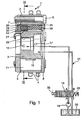
- Figures 1 and 2 show a device 1 for changing the timing an internal combustion engine.
- the device 1 consists essentially of a stator 2 and a concentrically arranged rotor 3.
- a drive wheel 4 is rotatably connected to the stator 2 and in the illustrated Embodiment designed as a sprocket. Likewise conceivable are embodiments of the drive wheel 4 as a belt or gear.
- the stator 2 is rotatably mounted on the rotor 3, wherein on the inner circumferential surface of the stator 2 in the illustrated embodiment five circumferentially spaced apart Recesses 5 are provided.
- the recesses 5 are in radial Direction from the stator 2 and the rotor 3, in the circumferential direction of two side walls 6 of the stator 2 and in the axial direction by a first and a second side cover 7, 8 limited. Each of the recesses 5 is on this Sealed pressure-tight manner.
- the first and second side covers 7, 8 are connected to the stator 2 by means of connecting elements 9, for example screws, connected.
- each vane groove 10th On the outer circumferential surface of the rotor 3 are axially extending vane grooves 10th formed, wherein in each vane groove 10, a radially extending wing 11th is arranged. In each recess 5, a wing 11 extends, wherein the Wing 11 in the radial direction on the stator 2 and in the axial direction on the side covers 7, 8 abut. Each wing 11 divides a recess 5 in two against each other working pressure chambers 12, 13. To a pressure-tight concern to ensure the wing 11 on the stator 2, are between the Nutgen 14 of the wing grooves 10 and the wings 11 leaf spring elements 15 attached, which act on the wing 11 in the radial direction with a force.
- first and second pressure medium lines 16, 17, the first and second pressure chambers 12, 13 via a control valve 18 with a pressure medium pump 19 or a tank 20 are connected.
- This will be an actuator formed, the relative rotation of the stator 2 relative to the Rotor 3 allows.
- either all first pressure chambers 12 with the pressure medium pump 19 and all second pressure chambers 13 be connected to the tank 20 or the exact opposite configuration.
- Be the first pressure chambers 12 with the pressure medium pump 19th and the second pressure chambers 13 connected to the tank 20 so stretch the first pressure chambers 12 at the expense of the second pressure chambers 13th out. This results in a displacement of the wings 11 in the circumferential direction, in the direction shown by the arrow 21.
- the rotor 3 is rotated relative to the stator 2.
- the stator 2 is in the illustrated embodiment by means of a on his Drive wheel 4 attacking, not shown chain drive from the crankshaft driven. Likewise conceivable is the drive of the stator 2 by means of a Belt or gear drive.
- the rotor 3 is a positive, positive or cohesive, for example, by means of press fit or by a screw connection means a central screw, connected to a camshaft, not shown. From the relative rotation of the rotor 3 relative to the stator 2, as a result of the supply or discharge of pressure medium to or from the pressure chambers 12, 13 results a phase shift between camshaft and crankshaft. By targeted introduction and discharge of pressure medium in the pressure chambers 12, 13 can thus the timing of the gas exchange valves of the internal combustion engine be selectively varied.
- the pressure medium lines 16, 17 are in the illustrated embodiment as essentially radially arranged bores extending from a Central bore 22 of the rotor 3 extend to the outer circumferential surface.
- a central valve not shown, arranged be, via which the pressure chambers 12, 13 specifically with the pressure medium pump 19 and the tank 20 can be connected.
- Another Possibility is within the central bore 22 a pressure medium distributor to arrange, the pressure medium lines 16, 17 via pressure medium channels and annular grooves with the terminals of an externally mounted control valve 18 connects.
- the substantially radially extending side walls 6 of the recesses 5 are provided with protrusions 23, which in the circumferential direction in the recesses 5 extend.
- the formations 23 serve as a stop for the Wing 11 and ensure that the pressure chambers 12, 13 with pressure medium can be supplied, even if the rotor 3 one of its two extreme positions relative to the stator 2 occupies, in which the wings 11 at one of Side walls 6 abut.
- the rotor 3 is due to the Alternating and dragging moments that the camshaft exerts on it are uncontrolled moved relative to the stator 2.
- the Camshaft drag torques the rotor relative to the stator in a circumferential direction, which is opposite to the direction of rotation of the stator until this strike against the side walls 6.
- the alternating moments which exerts the camshaft on the rotor 3 to a swinging back and forth of the rotor 3 and thus the wing 11 in the recesses 5, to at least one of the pressure chambers 12, 13 is completely filled with pressure medium. This leads to higher wear and noise developments in the device 1.
- a locking element 24 provided in an axial bore 25 of the rotor 3 .
- a pot-shaped piston 26 is arranged, which by a spring 27 in the axial Direction is applied with a force.
- the spring 27 is supported in the axial Direction on the one hand on a venting element 28 and is with its opposite axial end within the pot-shaped executed Plunger 26 is arranged.
- a backdrop 29 such formed so that the rotor 3 locked relative to the stator 2 in one position can be, which corresponds to the position during the start of the internal combustion engine. In this position, the piston 26 at insufficient pressure medium supply the device 1 urged by the spring 27 in the link 29.
- the pressure medium circuit 31 is also shown. From a tank 20 is by means of a pressure medium pump 19, a pressure medium connection P of a Control valve 18 supplied with pressure medium. At the same time is via a tank connection T pressure medium from the control valve 18 into the tank 20 passed.
- the control valve 18 also has two working ports A, B.
- an electromagnetic Actuator 32 against the spring force of a first spring element 33 acts, the control valve 18 can be placed in three positions. In a first position of the control valve 18, which is a de-energized State of the actuator 32 corresponds to the working port A with the Tank connection T and the pressure medium connection P with the working connection B and thus connected to the second pressure chamber 13.
- both the working connection A and the working connection B are both separated from the pressure medium connection P and from the tank connection T.
- a third position of the control valve 18 is the pressure medium connection P with the working port A and consequently connected to the first pressure chamber 12, while the second pressure chamber 13 via the working port B with the tank connection T is connected.
- an inventive control valve 18 is shown in longitudinal section.
- the essentially hollow-cylindrical valve housing 34 is provided with a radial pressure medium connection P, a radial tank connection T 1 , two working connections A, B and an axial tank connection T 2 .
- the radial ports P, T 1 , A, B are formed as axially spaced first annular grooves 35, which are introduced into the outer circumferential surface of the valve housing 34.
- the first annular grooves 35 are provided with a plurality of first openings 36, which open into the interior of the valve housing 34.
- a likewise substantially hollow cylindrical executed control piston 37 is arranged axially displaceable.
- An axial end of the control piston is pressure-tightly bounded by means of a wall section 37a.
- the wall portion 37a may be integral with the spool or separately configured.
- the control piston 37 can be gerbacht and held against the spring force of the first spring element 33 within two extreme values in an arbitrary position.
- the outer circumferential surface of the control piston 37 is provided with a second, a third and a fourth annular groove 38, 39, 40.
- the second and the third annular groove 38, 39 communicate with the interior of the control piston 37 via second and third openings 41, 42.
- the second annular groove 38 is designed such that it is in any position of the control piston 37 relative to the valve housing 34 with the first openings 36 the first annular groove 35 of the pressure medium connection P communicates.
- pressure medium from the pressure medium connection P passes through the second annular groove 38 and the second openings 41 in the interior of the control piston 37.
- the pressure medium passes through the third openings 42 and the third annular groove 39 to the working port B.
- pressure medium pressure medium from the second pressure chambers 12 is displaced to the working port A and passes through the first openings 36 to the axially arranged tank port T 2 .
- the electromagnetic actuator 32 is energized, the control piston 37 is displaced against the spring force of the first spring element 33.
- the coverage of the first openings 36 of the working port B by a first control edge 43 of the third annular groove 39 increases.
- the coverage of the first openings 36 of the working port A by a second control edge 44 of the control piston 37 increases. If the control piston 37 reaches a central position (not shown), the working connection A is no longer connected to the axial tank connection T 2 due to complete covering of the second control edge 44. Furthermore, neither the working port A nor the working port B communicates with the third annular groove 39. Alternatively, the control piston 37 may be designed such that in the center position both working ports A, B communicate with the third annular groove 39. If the control piston 37 is further displaced counter to the spring force of the first spring element 33, a third control edge 45 releases the first openings 36 of the working connection A to the third annular groove 39. Pressure medium flowing in from the pressure medium connection P now passes exclusively to the working connection A.
- the fourth annular groove 40 communicates both with the working connection B and with the radial tank connection T 1 .
- pressure medium from the pressure medium pump 19 passes into the first pressure chambers 12, which leads to a relative rotation of the rotor 3 to the stator 2.
- the displaced from the second pressure chambers 13 pressure fluid passes through the working port B and the fourth annular groove 40 to the radial tank port T first
- the third control edge 45 and the fourth annular groove 40 may be designed such that during the displacement of the control piston 37 first the working port A with the pressure medium pump 19 and then the working port B are connected to the tank 20.
- both compounds can be prepared simultaneously.
- the control piston 37 is at the axial end remote from the wall section 37a sealed pressure-tight by means of a cup-shaped sleeve 46. This is in Inside the control piston 37 fixed non-positively.
- the sleeve 46 may continue as a point of application of a push rod, not shown, of the actuator 32nd serve.
- the check valve 47 between the working ports A, B and the pressure medium connection P is arranged.
- the axial arrangement of the terminals in the order P - T - A - B or T - P - A - B, wherein the order of the working ports A, B is arbitrary, allows the arrangement of a check valve 47 within the control piston 37. It is only one Check valve 47 is necessary to protect the pressure medium circuit 31. The arrangement of the check valve 47 within the control piston 37 no additional space is needed. Another advantage is that, especially when using the control valve 18 as the central valve, the distance between the place where the pressure pulsations arise and the check valve 47 is minimal. Pressure fluctuations are intercepted practically at the place of origin.
- the check valve 47 consists of a spring-loaded locking body 48 which is urged by means of a second spring element 49 in a seat 50 of the check valve 47.
- the locking body 48, the second spring element 49 and the seat 50 are arranged within a cup-shaped housing 51.
- the second spring element 49 is supported on the bottom of the housing 51.
- the check valve 47 is pressed into the interior of the control piston 37.
- the components are designed such that a pressure-tight, non-positive connection between the inner circumferential surface of the control piston 37 and the housing 51 is produced. It is advantageous within the control piston 37 form an axial stop 52, which serves as a travel limit when pressing the check valve 47 in the control piston 37.
- the check valve 47 can be pressed away controlled. From a certain pressure of the locking body 48 is moved against the spring force of the second spring element 49 and the pressure medium passes through fourth openings 53 which are introduced into the bottom of the housing are to the third openings 42.
Landscapes
- Engineering & Computer Science (AREA)
- Mechanical Engineering (AREA)
- General Engineering & Computer Science (AREA)
- Valve Device For Special Equipments (AREA)
Applications Claiming Priority (4)
| Application Number | Priority Date | Filing Date | Title |
|---|---|---|---|
| DE102004023976 | 2004-05-14 | ||
| DE102004023976 | 2004-05-14 | ||
| DE102004038252 | 2004-08-06 | ||
| DE200410038252 DE102004038252A1 (de) | 2004-05-14 | 2004-08-06 | Steuerventil für eine Vorrichtung zur Veränderung der Steuerzeiten einer Brennkraftmaschine |
Publications (2)
| Publication Number | Publication Date |
|---|---|
| EP1596041A2 true EP1596041A2 (fr) | 2005-11-16 |
| EP1596041A3 EP1596041A3 (fr) | 2008-07-16 |
Family
ID=34935007
Family Applications (1)
| Application Number | Title | Priority Date | Filing Date |
|---|---|---|---|
| EP20050007929 Ceased EP1596041A3 (fr) | 2004-05-14 | 2005-04-12 | Valve de commande pour déphaseur d'arbre à cames de moteur à combustion interne |
Country Status (4)
| Country | Link |
|---|---|
| US (1) | US7533695B2 (fr) |
| EP (1) | EP1596041A3 (fr) |
| JP (1) | JP2005325841A (fr) |
| DE (1) | DE102004038252A1 (fr) |
Cited By (20)
| Publication number | Priority date | Publication date | Assignee | Title |
|---|---|---|---|---|
| WO2007025630A1 (fr) * | 2005-09-01 | 2007-03-08 | Schaeffler Kg | Soupape de distribution destinee a un dispositif pour modifier les temps de distribution d'un moteur a combustion |
| WO2007125050A3 (fr) * | 2006-05-03 | 2008-01-03 | Schaeffler Kg | Soupape pour un dispositif de reglage d'arbre a cames |
| WO2008077662A1 (fr) * | 2006-12-22 | 2008-07-03 | Schaeffler Kg | Soupape pour un dispositif de réglage d'arbre à cames |
| DE102007053688A1 (de) | 2007-11-10 | 2009-05-14 | Schaeffler Kg | Steuerventilanordnung für Nockenwellenversteller und mit dieser ausgerüsteter Nockenwellenversteller |
| DE102009008056A1 (de) | 2009-02-09 | 2010-08-12 | Schaeffler Technologies Gmbh & Co. Kg | Steuerventile zur Steuerung von Druckmittelströmen |
| DE102009024026A1 (de) | 2009-06-05 | 2010-12-09 | Schaeffler Technologies Gmbh & Co. Kg | Steuerventil zum Steuern von Druckmittelströmen mit integriertem Rückschlagventil |
| DE102009051310A1 (de) | 2009-10-29 | 2011-05-05 | Schaeffler Technologies Gmbh & Co. Kg | Befestigungsanordnung eines Nockenwellenverstellers |
| DE102009054052A1 (de) | 2009-11-20 | 2011-05-26 | Schaeffler Technologies Gmbh & Co. Kg | Schaltbare Vorrichtung zur Druckversorgung |
| DE102009054055A1 (de) | 2009-11-20 | 2011-05-26 | Schaeffler Technologies Gmbh & Co. Kg | Schaltbare Vorrichtung zur Druckversorgung |
| DE102009054053A1 (de) | 2009-11-20 | 2011-05-26 | Schaeffler Technologies Gmbh & Co. Kg | Druckspeicher und hydraulisches System |
| DE102009054050A1 (de) | 2009-11-20 | 2011-05-26 | Schaeffler Technologies Gmbh & Co. Kg | Schaltbare Vorrichtung zur Druckversorgung |
| DE102009054051A1 (de) | 2009-11-20 | 2011-05-26 | Schaeffler Technologies Gmbh & Co. Kg | Schaltbare Vorrichtung zur Druckversorgung mit passivem Zusatzdruckspeicher |
| EP2363579A1 (fr) * | 2010-02-24 | 2011-09-07 | Delphi Technologies, Inc. | Öldurchflussregelventil mit zwei Rückschlagventilen |
| US8118060B2 (en) | 2007-07-18 | 2012-02-21 | Schaeffer Technologies GmbH & Co. KG | Valve part of a hydraulic control valve for controlling flows of pressurized medium |
| US8272403B2 (en) | 2007-07-18 | 2012-09-25 | Schaeffler Technologies AG & Co. KG | Valve part of a hydraulic control valve |
| WO2013174531A1 (fr) * | 2012-05-25 | 2013-11-28 | Schaeffler Technologies AG & Co. KG | Soupape de commande d'un déphaseur d'arbre à cames |
| WO2014075665A1 (fr) * | 2012-11-13 | 2014-05-22 | Schaeffler Technologies AG & Co. KG | Soupape de commande pour dispositif hydraulique à verrouillage |
| EP2860363A1 (fr) * | 2013-08-27 | 2015-04-15 | Aisin Seiki Kabushiki Kaisha | Soupape de commande et structure de fixation de soupape de commande |
| DE102014207989A1 (de) | 2014-04-29 | 2015-10-29 | Schaeffler Technologies AG & Co. KG | Hydraulischer Phasensteller einer Nockenwelle |
| CN107208504A (zh) * | 2015-01-15 | 2017-09-26 | 舍弗勒技术股份两合公司 | 具有流出通道的控制阀 |
Families Citing this family (42)
| Publication number | Priority date | Publication date | Assignee | Title |
|---|---|---|---|---|
| DE102004036096B4 (de) * | 2004-07-24 | 2017-09-14 | Schaeffler Technologies AG & Co. KG | Steuerventil für eine Vorrichtung zur Veränderung der Steuerzeiten einer Brennkraftmaschine |
| DE102005047641A1 (de) | 2005-10-05 | 2007-04-12 | Schaeffler Kg | Steuerventil für einen Nockenwellenversteller |
| DE102006008861B4 (de) * | 2006-02-25 | 2008-08-14 | Hofer Mechatronik Gmbh | Nockenwellenversteller für eine Brennkraftmaschine |
| DE102006031595A1 (de) * | 2006-07-08 | 2008-02-21 | Schaeffler Kg | Hydraulisches Spannsystem |
| DE102006061104A1 (de) | 2006-12-22 | 2008-06-26 | Schaeffler Kg | Verfahren zum Bestimmen eines Tastverhältnisses für ein Ventil eines Nockenwellenverstellers |
| DE102007015333B4 (de) | 2007-03-30 | 2020-08-27 | Schaeffler Technologies AG & Co. KG | Steuerventil und Herstellungsverfahren für das Steuerventil |
| EP2006499A3 (fr) * | 2007-06-07 | 2008-12-31 | Delphi Technologies, Inc. | Mécanisme de blocage pour déphaseur d'arbre à cames |
| DE102008004591A1 (de) * | 2008-01-16 | 2009-07-23 | Schaeffler Kg | Hydraulisches Steuerventil mit integriertem Rückschlagventil |
| ATE512285T1 (de) | 2008-06-19 | 2011-06-15 | Hydraulik Ring Gmbh | Ventil zum verschwenken einer nockenwelle |
| DE102008030058B4 (de) | 2008-06-27 | 2010-06-17 | Hydraulik-Ring Gmbh | Nockenwellenverstelleinrichtung und geeignetes Ventil dafür |
| DE102008030057B4 (de) | 2008-06-27 | 2018-01-25 | Hilite Germany Gmbh | Nockenwellenverstelleinrichtung |
| CN102066701B (zh) | 2008-07-17 | 2013-06-12 | 三菱电机株式会社 | 可变阀定时调整装置用电磁阀及可变阀定时调整系统 |
| US20100084019A1 (en) * | 2008-10-08 | 2010-04-08 | Schaeffler Kg | Central spool valve |
| DE102009022869A1 (de) * | 2009-05-27 | 2010-12-09 | Hydraulik-Ring Gmbh | Flügelzellennockenwellenverstellersystem |
| JP2011064105A (ja) * | 2009-09-16 | 2011-03-31 | Hitachi Automotive Systems Ltd | 内燃機関のバルブタイミング制御装置 |
| DE102009050779B4 (de) | 2009-10-27 | 2016-05-04 | Hilite Germany Gmbh | Schwenkmotornockenwellenversteller mit einer Reibscheibe und Montageverfahren |
| DE102009052841A1 (de) | 2009-11-13 | 2011-05-19 | Hydraulik-Ring Gmbh | Nockenwelleneinsatz |
| KR101134973B1 (ko) * | 2009-11-19 | 2012-04-09 | 기아자동차주식회사 | 엔진 브레이크 및 이를 포함하는 엔진 |
| DE102010009401A1 (de) * | 2010-02-26 | 2011-09-01 | Schaeffler Technologies Gmbh & Co. Kg | Proportionalventil, insbesondere für einen Nockenwellenversteller |
| DE102010045358A1 (de) | 2010-04-10 | 2011-10-13 | Hydraulik-Ring Gmbh | Schwenkmotornockenwellenversteller mit einem Hydraulikventil |
| DE102010019005B4 (de) | 2010-05-03 | 2017-03-23 | Hilite Germany Gmbh | Schwenkmotorversteller |
| DE102010023863A1 (de) | 2010-06-15 | 2011-12-15 | Hydraulik-Ring Gmbh | Gebaute Nockenwelle mit einem Schwenkmotorversteller |
| DE102010032251A1 (de) * | 2010-07-26 | 2012-01-26 | Schaeffler Technologies Gmbh & Co. Kg | Rückschlagventil sowie hydraulisches Ventil mit einem eingebauten Rückschlagventil |
| DE102010050813A1 (de) | 2010-11-09 | 2012-05-10 | Schaeffler Technologies Gmbh & Co. Kg | Steuerkolben für ein Zentralventil eines Nockenwellenverstellers sowie ein Zentralventil und ein Nockenwellenversteller |
| US8695548B2 (en) | 2010-12-10 | 2014-04-15 | Denso Corporation | Valve timing control apparatus |
| JP5152313B2 (ja) * | 2010-12-10 | 2013-02-27 | 株式会社デンソー | バルブタイミング調整装置 |
| DE102010061337B4 (de) | 2010-12-20 | 2015-07-09 | Hilite Germany Gmbh | Hydraulikventil für einen Schwenkmotorversteller |
| US8662039B2 (en) * | 2011-03-16 | 2014-03-04 | Delphi Technologies, Inc. | Camshaft phaser with coaxial control valves |
| JP2012241740A (ja) * | 2011-05-16 | 2012-12-10 | Denso Corp | ソレノイドバルブおよび油圧制御装置 |
| JP5360173B2 (ja) * | 2011-09-15 | 2013-12-04 | 株式会社デンソー | バルブタイミング調整装置 |
| DE102011084059B4 (de) | 2011-10-05 | 2016-12-08 | Schwäbische Hüttenwerke Automotive GmbH | Steuerventil mit integriertem Filter und Nockenwellen-Phasensteller mit dem Steuerventil |
| DE102012106096B3 (de) * | 2012-07-06 | 2014-05-15 | Hilite Germany Gmbh | Schwenkmotorversteller mit einem Hydraulikventil |
| JP5842767B2 (ja) * | 2012-08-21 | 2016-01-13 | 株式会社デンソー | バルブタイミング調整装置 |
| US9322416B2 (en) * | 2013-03-11 | 2016-04-26 | Hydraforce, Inc. | Multi-functional proportional control valve for hydraulic suspension system for vehicle |
| JP5839239B2 (ja) | 2013-05-14 | 2016-01-06 | 株式会社デンソー | バルブタイミング調整装置 |
| JP6015605B2 (ja) | 2013-09-17 | 2016-10-26 | 株式会社デンソー | バルブタイミング調整装置 |
| DE102014103400B3 (de) * | 2014-03-13 | 2015-06-03 | Hilite Germany Gmbh | Hydraulikventil für einen Schwenkmotorversteller einer Nockenwelle |
| CN112682122B (zh) | 2016-10-06 | 2022-09-09 | 博格华纳公司 | 用于可变凸轮正时系统的双瓣阀 |
| US11111827B2 (en) | 2016-10-06 | 2021-09-07 | Borgwarner, Inc. | Double flapper valve for a variable cam timing system |
| US11459220B2 (en) * | 2017-11-30 | 2022-10-04 | Danfoss Power Solution II Technology A/S | Hydraulic system with load sense and methods thereof |
| US11187330B2 (en) * | 2018-04-17 | 2021-11-30 | Hydraforce, Inc. | Hydraulic balancing control valve and ride control system incorporating same |
| US20210230967A1 (en) * | 2020-01-24 | 2021-07-29 | PumpOne Environmental, LLC | Multi-function valve |
Citations (1)
| Publication number | Priority date | Publication date | Assignee | Title |
|---|---|---|---|---|
| DE10215939C1 (de) | 2002-04-11 | 2003-08-21 | Ina Schaeffler Kg | Elektromagnetisches Hydtaulikventil, insbesondere Proportionalventil zur Steuerung einer Vorrichtung zur Drehwinkelverstellung einer Nockenwelle gegenüber einer Kurbelwelle einer Brennkraftmaschine, sowie Verfahren zu dessen Herstellung |
Family Cites Families (16)
| Publication number | Priority date | Publication date | Assignee | Title |
|---|---|---|---|---|
| US2876796A (en) * | 1954-11-12 | 1959-03-10 | Int Harvester Co | Minimum displacement balanced control valve |
| GB1252581A (fr) * | 1968-02-12 | 1971-11-10 | ||
| DE3302000A1 (de) * | 1983-01-21 | 1984-07-26 | Danfoss A/S, Nordborg | Hydraulisches schieberventil |
| US5289805A (en) * | 1992-03-05 | 1994-03-01 | Borg-Warner Automotive Transmission & Engine Components Corporation | Self-calibrating variable camshaft timing system |
| US5205249A (en) * | 1992-05-14 | 1993-04-27 | Borg-Warner Automotive Transmission & Engine Components Corporation | Variable camshaft timing system for internal combustion engine utilizing flywheel energy for reduced camshaft torsionals |
| US5263443A (en) * | 1993-01-14 | 1993-11-23 | Ford Motor Company | Hydraulic phaseshifter |
| US5367992A (en) * | 1993-07-26 | 1994-11-29 | Borg-Warner Automotive, Inc. | Variable camshaft timing system for improved operation during low hydraulic fluid pressure |
| JP3374475B2 (ja) * | 1993-11-16 | 2003-02-04 | 株式会社デンソー | バルブタイミング調整装置 |
| JP3666072B2 (ja) * | 1995-09-13 | 2005-06-29 | アイシン精機株式会社 | 切替弁 |
| WO2001020202A1 (fr) * | 1999-09-14 | 2001-03-22 | Mitsubishi Denki Kabushiki Kaisha | Valve de controle d'huile |
| DE19958541A1 (de) * | 1999-12-04 | 2001-06-07 | Schaeffler Waelzlager Ohg | Vorrichtung zur Drehwinkelverstellung einer Nockenwelle |
| DE10029261A1 (de) * | 2000-06-14 | 2001-12-20 | Deutz Ag | Nockenwellenverschwenkeinrichtung |
| US20030033998A1 (en) * | 2001-08-14 | 2003-02-20 | Marty Gardner | Hybrid multi-position cam indexer having controls located in rotor |
| DE10229912B4 (de) * | 2002-07-04 | 2012-12-13 | Schaeffler Technologies AG & Co. KG | Elektromagnetisches Hydraulikventil, insbesondere Proportionalventil zur Steuerung einer Vorrichtung zur Drehwinkelverstellung einer Nockenwelle gegenüber einer Kurbelwelle einer Brennkraftmaschine |
| DE10300974A1 (de) * | 2003-01-14 | 2004-07-22 | Hydraulik-Ring Gmbh | Proportionalmagnetventil einer Nockenwellenverstelleinrichtung für Kraftfahrzeuge |
| DE102004036096B4 (de) * | 2004-07-24 | 2017-09-14 | Schaeffler Technologies AG & Co. KG | Steuerventil für eine Vorrichtung zur Veränderung der Steuerzeiten einer Brennkraftmaschine |
-
2004
- 2004-08-06 DE DE200410038252 patent/DE102004038252A1/de not_active Ceased
-
2005
- 2005-04-12 EP EP20050007929 patent/EP1596041A3/fr not_active Ceased
- 2005-05-12 US US11/127,902 patent/US7533695B2/en not_active Expired - Fee Related
- 2005-05-13 JP JP2005141754A patent/JP2005325841A/ja active Pending
Patent Citations (1)
| Publication number | Priority date | Publication date | Assignee | Title |
|---|---|---|---|---|
| DE10215939C1 (de) | 2002-04-11 | 2003-08-21 | Ina Schaeffler Kg | Elektromagnetisches Hydtaulikventil, insbesondere Proportionalventil zur Steuerung einer Vorrichtung zur Drehwinkelverstellung einer Nockenwelle gegenüber einer Kurbelwelle einer Brennkraftmaschine, sowie Verfahren zu dessen Herstellung |
Cited By (36)
| Publication number | Priority date | Publication date | Assignee | Title |
|---|---|---|---|---|
| US7849825B2 (en) | 2005-09-01 | 2010-12-14 | Schaeffler Technologies Gmbh & Co. Kg | Control valve for a device for changing the control times of an internal combustion engine |
| WO2007025630A1 (fr) * | 2005-09-01 | 2007-03-08 | Schaeffler Kg | Soupape de distribution destinee a un dispositif pour modifier les temps de distribution d'un moteur a combustion |
| WO2007125050A3 (fr) * | 2006-05-03 | 2008-01-03 | Schaeffler Kg | Soupape pour un dispositif de reglage d'arbre a cames |
| WO2008077662A1 (fr) * | 2006-12-22 | 2008-07-03 | Schaeffler Kg | Soupape pour un dispositif de réglage d'arbre à cames |
| DE102006061105B4 (de) | 2006-12-22 | 2018-09-13 | Schaeffler Technologies AG & Co. KG | Ventil für einen Nockenwellenversteller und ein Verfahren zum Betreiben des Ventils |
| US8118060B2 (en) | 2007-07-18 | 2012-02-21 | Schaeffer Technologies GmbH & Co. KG | Valve part of a hydraulic control valve for controlling flows of pressurized medium |
| US8272403B2 (en) | 2007-07-18 | 2012-09-25 | Schaeffler Technologies AG & Co. KG | Valve part of a hydraulic control valve |
| DE102007053688A1 (de) | 2007-11-10 | 2009-05-14 | Schaeffler Kg | Steuerventilanordnung für Nockenwellenversteller und mit dieser ausgerüsteter Nockenwellenversteller |
| WO2010089239A1 (fr) | 2009-02-09 | 2010-08-12 | Schaeffler Technologies Gmbh & Co. Kg | Soupapes de distribution pour la distribution de flux de fluide sous pression |
| DE102009008056A1 (de) | 2009-02-09 | 2010-08-12 | Schaeffler Technologies Gmbh & Co. Kg | Steuerventile zur Steuerung von Druckmittelströmen |
| US8839820B2 (en) | 2009-02-09 | 2014-09-23 | Schaeffler Technologies AG & Co. KG | Control valves for controlling pressure medium flows |
| DE102009024026A1 (de) | 2009-06-05 | 2010-12-09 | Schaeffler Technologies Gmbh & Co. Kg | Steuerventil zum Steuern von Druckmittelströmen mit integriertem Rückschlagventil |
| DE102009024026B4 (de) | 2009-06-05 | 2022-12-08 | Schaeffler Technologies AG & Co. KG | Steuerventil zum Steuern von Druckmittelströmen mit integriertem Rückschlagventil |
| US8757114B2 (en) | 2009-06-05 | 2014-06-24 | Schaeffler Technologies Gmbh & Co. Kg | Control valve for controlling pressure-medium flows comprising an integrated check valve |
| DE102009051310A1 (de) | 2009-10-29 | 2011-05-05 | Schaeffler Technologies Gmbh & Co. Kg | Befestigungsanordnung eines Nockenwellenverstellers |
| US8899198B2 (en) | 2009-10-29 | 2014-12-02 | Schaeffler Technologies Gmbh & Co. Kg | Fastening assembly of a camshaft adjuster |
| WO2011051378A2 (fr) | 2009-10-29 | 2011-05-05 | Schaeffler Technologies Gmbh & Co. Kg | Système de fixation d'un déphaseur d'arbre à cames |
| US8485152B2 (en) | 2009-11-20 | 2013-07-16 | Schaeffler Technologies AG & Co. KG | Switchable pressure supply device comprising a passive auxiliary pressure accumulator |
| DE102009054052A1 (de) | 2009-11-20 | 2011-05-26 | Schaeffler Technologies Gmbh & Co. Kg | Schaltbare Vorrichtung zur Druckversorgung |
| DE102009054055A1 (de) | 2009-11-20 | 2011-05-26 | Schaeffler Technologies Gmbh & Co. Kg | Schaltbare Vorrichtung zur Druckversorgung |
| US8752518B2 (en) | 2009-11-20 | 2014-06-17 | Schaeffler Technologies Gmbh & Co. Kg | Switchable pressure supply device |
| DE102009054051A1 (de) | 2009-11-20 | 2011-05-26 | Schaeffler Technologies Gmbh & Co. Kg | Schaltbare Vorrichtung zur Druckversorgung mit passivem Zusatzdruckspeicher |
| US8813709B2 (en) | 2009-11-20 | 2014-08-26 | Schaeffler Technologies Gmbh & Co. Kg | Switchable pressure supply device |
| DE102009054050A1 (de) | 2009-11-20 | 2011-05-26 | Schaeffler Technologies Gmbh & Co. Kg | Schaltbare Vorrichtung zur Druckversorgung |
| DE102009054053A1 (de) | 2009-11-20 | 2011-05-26 | Schaeffler Technologies Gmbh & Co. Kg | Druckspeicher und hydraulisches System |
| DE102009054052B4 (de) | 2009-11-20 | 2018-08-23 | Schaeffler Technologies AG & Co. KG | Schaltbare Vorrichtung zur Druckversorgung |
| EP2363579A1 (fr) * | 2010-02-24 | 2011-09-07 | Delphi Technologies, Inc. | Öldurchflussregelventil mit zwei Rückschlagventilen |
| US9458942B2 (en) | 2012-05-25 | 2016-10-04 | Schaeffler Technologies AG & Co. KG | Control valve for a camshaft adjuster |
| WO2013174531A1 (fr) * | 2012-05-25 | 2013-11-28 | Schaeffler Technologies AG & Co. KG | Soupape de commande d'un déphaseur d'arbre à cames |
| US9611763B2 (en) | 2012-11-13 | 2017-04-04 | Schaeffler Technologies AG & Co. KG | Control valve for a hydraulic apparatus with locking facility |
| WO2014075665A1 (fr) * | 2012-11-13 | 2014-05-22 | Schaeffler Technologies AG & Co. KG | Soupape de commande pour dispositif hydraulique à verrouillage |
| US9447896B2 (en) | 2013-08-27 | 2016-09-20 | Aisin Seiki Kabushiki Kaisha | Control valve and attachment structure of control valve |
| EP2860363A1 (fr) * | 2013-08-27 | 2015-04-15 | Aisin Seiki Kabushiki Kaisha | Soupape de commande et structure de fixation de soupape de commande |
| WO2015165444A1 (fr) | 2014-04-29 | 2015-11-05 | Schaeffler Technologies AG & Co. KG | Déphaseur hydraulique d'un arbre à cames |
| DE102014207989A1 (de) | 2014-04-29 | 2015-10-29 | Schaeffler Technologies AG & Co. KG | Hydraulischer Phasensteller einer Nockenwelle |
| CN107208504A (zh) * | 2015-01-15 | 2017-09-26 | 舍弗勒技术股份两合公司 | 具有流出通道的控制阀 |
Also Published As
| Publication number | Publication date |
|---|---|
| DE102004038252A1 (de) | 2005-12-15 |
| EP1596041A3 (fr) | 2008-07-16 |
| US20050252561A1 (en) | 2005-11-17 |
| JP2005325841A (ja) | 2005-11-24 |
| US7533695B2 (en) | 2009-05-19 |
Similar Documents
| Publication | Publication Date | Title |
|---|---|---|
| EP1596041A2 (fr) | Valve de commande pour déphaseur d'arbre à cames de moteur à combustion interne | |
| DE102004036096B4 (de) | Steuerventil für eine Vorrichtung zur Veränderung der Steuerzeiten einer Brennkraftmaschine | |
| EP1596040B1 (fr) | Déphaseur d'arbre à cames | |
| EP1924759B1 (fr) | Soupape de distribution destinee a un dispositif pour modifier les temps de distribution d'un moteur a combustion | |
| DE69204751T2 (de) | Variable Nockenwellenzeitsteuerung für Brennkraftmaschine. | |
| EP1914395B1 (fr) | Procédé de commande d'un appareil pour modifier le calage des soupapes d'un moteur à combustion interne | |
| DE102005052481A1 (de) | Steuerventil für eine Vorrichtung zur variablen Einstellung der Steuerzeiten von Gaswechselventilen einer Brennkraftmaschine | |
| EP2021588A1 (fr) | Soupape de commande pour un dispositif de réglage d'arbre à cames | |
| EP1896699B1 (fr) | Soupape de commande pour un dispositif de reglage variable des temps de commande de soupapes d'echange des gaz d'un moteur a combustion interne | |
| DE102004038160B4 (de) | Nockenwellenversteller | |
| EP1825106B1 (fr) | Soupape de commande | |
| DE102010008001A1 (de) | Vorrichtung zur variablen Einstellung von Ventilerhebungskurven von Gaswechselventilen einer Brennkraftmaschine | |
| EP1653056B1 (fr) | Dispositif de variation de calage des soupapes de moteur à combustion interne | |
| DE102005013402A1 (de) | Vorrichtung zur Veränderung der Steuerzeiten einer Brennkraftmaschine | |
| EP1888895B1 (fr) | Dispositif de reglage variable des temps de commande de soupapes d'echange des gaz d'un moteur a combustion interne | |
| DE102005024241B4 (de) | Vorrichtung zur variablen Einstellung der Steuerzeiten von Gaswechselventilen einer Brennkraftmaschine | |
| DE102005023228B4 (de) | Vorrichtung zur variablen Einstellung der Steuerzeiten von Gaswechselventilen einer Brennkraftmaschine | |
| DE102005024242B4 (de) | Vorrichtung zur variablen Einstellung der Steuerzeiten von Gaswechselventilen einer Brennkraftmaschine |
Legal Events
| Date | Code | Title | Description |
|---|---|---|---|
| PUAI | Public reference made under article 153(3) epc to a published international application that has entered the european phase |
Free format text: ORIGINAL CODE: 0009012 |
|
| 17P | Request for examination filed |
Effective date: 20050412 |
|
| AK | Designated contracting states |
Kind code of ref document: A2 Designated state(s): AT BE BG CH CY CZ DE DK EE ES FI FR GB GR HU IE IS IT LI LT LU MC NL PL PT RO SE SI SK TR |
|
| AX | Request for extension of the european patent |
Extension state: AL BA HR LV MK YU |
|
| RAP1 | Party data changed (applicant data changed or rights of an application transferred) |
Owner name: SCHAEFFLER KG |
|
| PUAL | Search report despatched |
Free format text: ORIGINAL CODE: 0009013 |
|
| AK | Designated contracting states |
Kind code of ref document: A3 Designated state(s): AT BE BG CH CY CZ DE DK EE ES FI FR GB GR HU IE IS IT LI LT LU MC NL PL PT RO SE SI SK TR |
|
| AX | Request for extension of the european patent |
Extension state: AL BA HR LV MK YU |
|
| AKX | Designation fees paid |
Designated state(s): DE FR GB IT |
|
| 17Q | First examination report despatched |
Effective date: 20090710 |
|
| STAA | Information on the status of an ep patent application or granted ep patent |
Free format text: STATUS: THE APPLICATION HAS BEEN REFUSED |
|
| 18R | Application refused |
Effective date: 20100226 |
|
| P01 | Opt-out of the competence of the unified patent court (upc) registered |
Effective date: 20230522 |