EP1596076A1 - Dispositiv de fixation d'au moins deux pièces, utilisation et un procede de ce dispositiv - Google Patents
Dispositiv de fixation d'au moins deux pièces, utilisation et un procede de ce dispositiv Download PDFInfo
- Publication number
- EP1596076A1 EP1596076A1 EP04291231A EP04291231A EP1596076A1 EP 1596076 A1 EP1596076 A1 EP 1596076A1 EP 04291231 A EP04291231 A EP 04291231A EP 04291231 A EP04291231 A EP 04291231A EP 1596076 A1 EP1596076 A1 EP 1596076A1
- Authority
- EP
- European Patent Office
- Prior art keywords
- parts
- shaped
- element according
- body part
- connecting element
- Prior art date
- Legal status (The legal status is an assumption and is not a legal conclusion. Google has not performed a legal analysis and makes no representation as to the accuracy of the status listed.)
- Granted
Links
- 238000000034 method Methods 0.000 title claims abstract description 6
- 230000000149 penetrating effect Effects 0.000 claims description 5
- 230000000903 blocking effect Effects 0.000 claims description 3
- 238000003780 insertion Methods 0.000 claims description 2
- 230000037431 insertion Effects 0.000 claims description 2
- 239000002184 metal Substances 0.000 claims description 2
- 239000013013 elastic material Substances 0.000 claims 1
- 230000005489 elastic deformation Effects 0.000 description 1
- 210000002414 leg Anatomy 0.000 description 1
- 238000012423 maintenance Methods 0.000 description 1
- 230000008439 repair process Effects 0.000 description 1
- 239000012858 resilient material Substances 0.000 description 1
- 230000000284 resting effect Effects 0.000 description 1
- 230000008719 thickening Effects 0.000 description 1
- 210000000689 upper leg Anatomy 0.000 description 1
Images

Classifications
-
- F—MECHANICAL ENGINEERING; LIGHTING; HEATING; WEAPONS; BLASTING
- F16—ENGINEERING ELEMENTS AND UNITS; GENERAL MEASURES FOR PRODUCING AND MAINTAINING EFFECTIVE FUNCTIONING OF MACHINES OR INSTALLATIONS; THERMAL INSULATION IN GENERAL
- F16B—DEVICES FOR FASTENING OR SECURING CONSTRUCTIONAL ELEMENTS OR MACHINE PARTS TOGETHER, e.g. NAILS, BOLTS, CIRCLIPS, CLAMPS, CLIPS OR WEDGES; JOINTS OR JOINTING
- F16B5/00—Joining sheets or plates, e.g. panels, to one another or to strips or bars parallel to them
- F16B5/06—Joining sheets or plates, e.g. panels, to one another or to strips or bars parallel to them by means of clamps or clips
- F16B5/0607—Joining sheets or plates, e.g. panels, to one another or to strips or bars parallel to them by means of clamps or clips joining sheets or plates to each other
- F16B5/0621—Joining sheets or plates, e.g. panels, to one another or to strips or bars parallel to them by means of clamps or clips joining sheets or plates to each other in parallel relationship
- F16B5/0642—Joining sheets or plates, e.g. panels, to one another or to strips or bars parallel to them by means of clamps or clips joining sheets or plates to each other in parallel relationship the plates being arranged one on top of the other and in full close contact with each other
-
- F—MECHANICAL ENGINEERING; LIGHTING; HEATING; WEAPONS; BLASTING
- F16—ENGINEERING ELEMENTS AND UNITS; GENERAL MEASURES FOR PRODUCING AND MAINTAINING EFFECTIVE FUNCTIONING OF MACHINES OR INSTALLATIONS; THERMAL INSULATION IN GENERAL
- F16B—DEVICES FOR FASTENING OR SECURING CONSTRUCTIONAL ELEMENTS OR MACHINE PARTS TOGETHER, e.g. NAILS, BOLTS, CIRCLIPS, CLAMPS, CLIPS OR WEDGES; JOINTS OR JOINTING
- F16B19/00—Bolts without screw-thread; Pins, including deformable elements; Rivets
- F16B19/04—Rivets; Spigots or the like fastened by riveting
- F16B19/08—Hollow rivets; Multi-part rivets
- F16B19/10—Hollow rivets; Multi-part rivets fastened by expanding mechanically
- F16B19/1027—Multi-part rivets
- F16B19/1036—Blind rivets
- F16B19/1081—Blind rivets fastened by a drive-pin
-
- F—MECHANICAL ENGINEERING; LIGHTING; HEATING; WEAPONS; BLASTING
- F16—ENGINEERING ELEMENTS AND UNITS; GENERAL MEASURES FOR PRODUCING AND MAINTAINING EFFECTIVE FUNCTIONING OF MACHINES OR INSTALLATIONS; THERMAL INSULATION IN GENERAL
- F16B—DEVICES FOR FASTENING OR SECURING CONSTRUCTIONAL ELEMENTS OR MACHINE PARTS TOGETHER, e.g. NAILS, BOLTS, CIRCLIPS, CLAMPS, CLIPS OR WEDGES; JOINTS OR JOINTING
- F16B21/00—Means for preventing relative axial movement of a pin, spigot, shaft or the like and a member surrounding it; Stud-and-socket releasable fastenings
- F16B21/02—Releasable fastening devices locking by rotation
-
- F—MECHANICAL ENGINEERING; LIGHTING; HEATING; WEAPONS; BLASTING
- F16—ENGINEERING ELEMENTS AND UNITS; GENERAL MEASURES FOR PRODUCING AND MAINTAINING EFFECTIVE FUNCTIONING OF MACHINES OR INSTALLATIONS; THERMAL INSULATION IN GENERAL
- F16B—DEVICES FOR FASTENING OR SECURING CONSTRUCTIONAL ELEMENTS OR MACHINE PARTS TOGETHER, e.g. NAILS, BOLTS, CIRCLIPS, CLAMPS, CLIPS OR WEDGES; JOINTS OR JOINTING
- F16B21/00—Means for preventing relative axial movement of a pin, spigot, shaft or the like and a member surrounding it; Stud-and-socket releasable fastenings
- F16B21/06—Releasable fastening devices with snap-action
- F16B21/07—Releasable fastening devices with snap-action in which the socket has a resilient part
- F16B21/073—Releasable fastening devices with snap-action in which the socket has a resilient part the socket having a resilient part on its inside
Definitions
- the present invention relates to a Connecting element for releasably connecting at least two plate-shaped in a connection area, itself at least partially overlapping parts according to The preamble of claim 1, as well as such Connecting elements having housing after the The preamble of claim 11 and a method for releasably connecting at least two in one Connection area plate-shaped, at least partially overlapping parts according to the preamble of Claim 12.
- housing as different structures as about a control cabinet of an electronic device, a housing of a device and a body of a Motor vehicle understood as far as they are due to their Scope of application similar loads, such as Example vibrations, subject.
- All these cases are about one or two several plate-shaped parts on one at least in Mounting or connecting area flat, plate-shaped part of a basic structure or else two or more such parts to each other Fasten.
- the attachment should be, for example be vibration resistant and not as a screw connection be designed because such in vibration resistant Version is very costly.
- the invention is therefore based on the object to propose a connecting element that is suitable Parts releasably connect with each other, at least in a connection region are plate-shaped and at least partially overlap. It should be the Connecting element only from the front of the be operated to be connected parts ago.
- the object is further achieved by a housing, having the connecting elements according to claim 1, as well as by a method for detachably connecting parts, having the features of claim 12.
- the connecting element according to the invention has two Components on, and that a first element by the parts to be connected pass through and is elastically deformable, as well as a second, not deformable element, which is the first element in a Connection position blocked.
- the first element has a head part with which it comes to rest on the part through which it interconnecting the parts first to be led.
- the first element further includes Hull part, starting from the headboard first extends with constant cross section and then at least having two symmetrically arranged bulges.
- the Bulges are shaped so that they pass through the part the first element when connecting the Parts performed last, reach behind.
- Of the section extending at a constant cross section of the body part is dimensioned in its length so that he at least approximately, preferably exactly, the total thickness corresponds to the parts to be joined together.
- the holes in the interconnecting Parts are each arranged so that when Overlay the parts to be joined together results in a single through hole in the connection area, in which the connecting element is used and that the Crossing the connecting element completely.
- the fuselage part of the first element of two in the essentially in the longitudinal direction of the body part billowing, symmetrical to each other and to obtain the Bulges with transverse folds provided a strip formed of resilient material.
- the two strips at the free Ends connected together and at the headboard of the Connecting element separated by a slot corresponding to the Connecting element gives a greater spring force.
- the two are Strip at the free ends not together connected so that the body part to that of the head part opposite end represents an open element.
- this is Headboard of the first element of the invention Connecting element in two parts and plate-shaped formed, with the two parts of the head part on opposite sides of the trunk part are arranged.
- the two parts of the headboard can thereby, depending on the embodiment, approximately the same Have width as the two strips of the body part and in particular to join them.
- the two Parts of the headboard can also be around the Hull part extend around and in this way an almost complete annular top plate forming at the Inserting in the through hole for receiving the Connecting element on the part of each other too connecting parts comes up by which it is considered first is passed.
- each of the two parts of the head part of one of the strips associated with the body part is identical to a further feature of the invention.
- the first element is integrally formed, wherein the Hull part essentially U-shaped with two the Bulges having thighs is formed and each leg at its free end in a for Transverse longitudinal direction of the body part plate-shaped part of the two-part design Headboard passes.
- the first element can optionally be made of resilient Made of metal or plastic.
- the second element of the invention Connector element that serves to hold the first element in Blocking a connection position is preferred in the first element one to the longitudinal direction of the first Elements parallel axis rotatably arranged and can take at least two positions.
- the first Position is an assembly / disassembly position in which the first element for insertion into one another connecting parts piercing hole, or to Take out of the same, deformable.
- the second Position is a connection position in which the first Element is not deformable and so not from the parts to be joined together penetrating hole can be removed.
- the connecting element at least one latching element for locking the second Elements in the connection position.
- the Snap-in can, for example, by a Tip-shaped elevation in the head of the first element and a corresponding recess in the second element be formed.
- the object of the invention is further by a Housing solved, the one or more above Having described connecting elements.
- the erfindungsgzeße object is also by a Method for detachably connecting at least two in a connection area plate-shaped, at least partially overlapping parts by means of one of solved above connecting elements.
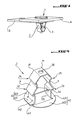
- FIG. 1 shows two plates connected to a connecting element according to the invention
- FIG. 2 shows a connecting element according to the invention in the connecting position
- Figure 3 shows a connecting element according to the invention in the mounting position
- Figure 4 shows one of the two parts forming the connecting element according to the invention.
- Figure 1 shows how an inventive Connecting element 1 two partially overlapping Parts A, B interconnects.
- the connecting element 1 which consists of a first, elastically deformable element. 2 and a second, rotatable in the first element 2 arranged and this in a connection position blocking element 3 passes through the to be joined together parts A, B in one provided rectangular hole.
- the first element 2 has a head part 4, with that it comes to rest on Part A when it passes through the parts A, B to be joined together is passed.
- the first element 2 also has a body part 5, which is from the headboard 4 with extends first constant cross section and then two consecutive pairs symmetrically arranged Has bulges. The first pair of bulges is shaped so that it is the part B, through which the first Element 2 when connecting the two parts A, B is passed last, engages behind.
- the body part 5 of the first element 2 consists of two substantially in the longitudinal direction of the body part extending, mutually symmetrical strips 6, 7th
- the two strips 6, 7 are at their from the headboard 4th opposite ends 61, 71 by a cross member 57th connected with each other. Since the two strips 6, 7 are formed symmetrically, the following applies Description of the strip 6 in an analogous manner also for the strip 7.
- the reference numerals each of the subsequently described sections each the two strips 6, 7 arranged in the figure 2 so that they are easy to read. So that's it regardless of whether a reference number on the strip 6 or on Strip 7 is plotted as it strips for both apply equally. A part of the reference signs finds otherwise in the figure 4.
- the strip 6 of the first element 2 has two Bulges 22, 24 on, with straight Alternate sections.
- the strip 6 thus has initially in the longitudinal direction of the first element 2 extending section 51, on the succession an outwardly folded portion 52, an inward one folded section 53, a longitudinal direction of the first element extending portion 54, an outward folded section 55 and one towards the middle folded back section 56. It forms the outwardly folded portion 52 with the again after inside folded portion 53, the first bulge 22nd and the outwardly folded portion 55 with the inside folded portion 56, the second bulge 24th In a corresponding manner in the strip 7 are the Bulges 23 and 25 formed.
- sections 52 and 55 are directed obliquely outwards, so for example not parallel to the longitudinal extent of first item 2, if necessary Remove the connecting element from the To facilitate through hole.
- Connecting element are the two ends of the strip. 6 and 7, denoted by the reference numerals 61, 62 and 71, 72 are marked with the head part 4 or with the two strips 6, 7 connecting crosspiece 57 connected.
- the second element 3 has a on the head part 4th the first element resting lid member 31, from which a flat, into a cylindrical axis leaking hull part connects, the following successive sections is formed: a Base portion 32 whose width is the distance between the two straight sections 51 of the two strips 6, 7 corresponds; a tapered portion 33; one narrow section 34; one essentially the same Width as section 34 having, but something thicker section 35, to the crossbar 57th zoom ranges; and finally a cylindrical one Section 36, which passes through a round hole 58 of the crosspiece 57th passed through.
- the section 35 is advantageously provided with an approximately conical thickening, whose shape is that of the top part of the section 56 of the first element 2 limited interior adapted is.
- the width of the section 32 prevents that second element 3 in the position shown in Figure 2 an elastic merging of the strips 6 and 7 and so that the second element 3 in the through hole of the Parts A, B inserted or removed from this can be.
- an elastic Deformation in particular a Auftechnologyzube admire the Stripes 6 and 7 in the context of elastic deformability of the first element 3 possible.
- element 2 is formed in two parts, wherein the two parts 41, 42 of the plate-shaped head part 4 opposite sides of the body part 5 are arranged.
- each of the two parts 41, 42 of the head part 4 is made one directly to the straight portion 51 of Strip 6 adjoining and across to this extending section 411 and a to it subsequent section 412, in addition to the strip 6 runs to the strip 7 out.
- an outwardly angled Section 421, from which starts a section 422 extends next to the strip 7 to the strip 6 out.
- the outgoing from the strip 6 section 412 runs it in a free end, not with the strip 7 or the subsequent section 421 is connected.
- Positioning aid can, for example, in a simple manner through a small conical elevation 81 on the Cover member 31 of the second element 3, on the the head part 4 facing surface, and a corresponding recess 82 in the head part 4, in the lid member 31 facing surface of the Sections 411, 421, be formed.
- the positioning aid 8 by two increases 81 and two recesses 82 are formed, each diametrically are arranged opposite, so that the lock regardless of whether the second element 3 in which is turned one way or the other.
Landscapes
- Engineering & Computer Science (AREA)
- General Engineering & Computer Science (AREA)
- Mechanical Engineering (AREA)
- Connection Of Plates (AREA)
Priority Applications (2)
| Application Number | Priority Date | Filing Date | Title |
|---|---|---|---|
| DE200450004287 DE502004004287D1 (de) | 2004-05-13 | 2004-05-13 | Verbindungselement zum lösbaren Verbinden von wenigstens zwei Teilen, sowie eine Verwendung und ein Verfahren mittels eines derartigen Verbindungselements |
| EP20040291231 EP1596076B1 (fr) | 2004-05-13 | 2004-05-13 | Dispositiv de fixation d'au moins deux pièces, utilisation et un procede de ce dispositiv |
Applications Claiming Priority (1)
| Application Number | Priority Date | Filing Date | Title |
|---|---|---|---|
| EP20040291231 EP1596076B1 (fr) | 2004-05-13 | 2004-05-13 | Dispositiv de fixation d'au moins deux pièces, utilisation et un procede de ce dispositiv |
Publications (2)
| Publication Number | Publication Date |
|---|---|
| EP1596076A1 true EP1596076A1 (fr) | 2005-11-16 |
| EP1596076B1 EP1596076B1 (fr) | 2007-07-11 |
Family
ID=34931099
Family Applications (1)
| Application Number | Title | Priority Date | Filing Date |
|---|---|---|---|
| EP20040291231 Expired - Lifetime EP1596076B1 (fr) | 2004-05-13 | 2004-05-13 | Dispositiv de fixation d'au moins deux pièces, utilisation et un procede de ce dispositiv |
Country Status (2)
| Country | Link |
|---|---|
| EP (1) | EP1596076B1 (fr) |
| DE (1) | DE502004004287D1 (fr) |
Cited By (4)
| Publication number | Priority date | Publication date | Assignee | Title |
|---|---|---|---|---|
| WO2012055535A1 (fr) * | 2010-10-25 | 2012-05-03 | Juwi R & D Research & Development Gmbh & Co. Kg | Élément de raccordement |
| FR2968366A1 (fr) * | 2010-12-02 | 2012-06-08 | Peugeot Citroen Automobiles Sa | Clip de fixation elastique. |
| CN103534059A (zh) * | 2011-08-03 | 2014-01-22 | 宝马股份公司 | 连接元件 |
| TWI509162B (zh) * | 2009-07-24 | 2015-11-21 | Pem Man Inc | 快速作用之面板緊固件 |
Citations (4)
| Publication number | Priority date | Publication date | Assignee | Title |
|---|---|---|---|---|
| GB1317752A (en) * | 1969-07-29 | 1973-05-23 | Amherd Ag | Connecting device for releasably connecting two structural members |
| DE3231893A1 (de) * | 1982-08-27 | 1984-03-01 | Daimler-Benz Ag, 7000 Stuttgart | Schnellverschluss |
| FR2790046A1 (fr) * | 1999-02-19 | 2000-08-25 | Rapid Sa | Dispositif de fixation de deux panneaux ou analogues forme de deux pieces cooperantes |
| DE10255902A1 (de) * | 2001-12-03 | 2003-06-18 | Vaillant Gmbh | Element zum Verbinden von Verkleidungsteilen an Rahmen |
-
2004
- 2004-05-13 EP EP20040291231 patent/EP1596076B1/fr not_active Expired - Lifetime
- 2004-05-13 DE DE200450004287 patent/DE502004004287D1/de not_active Expired - Lifetime
Patent Citations (4)
| Publication number | Priority date | Publication date | Assignee | Title |
|---|---|---|---|---|
| GB1317752A (en) * | 1969-07-29 | 1973-05-23 | Amherd Ag | Connecting device for releasably connecting two structural members |
| DE3231893A1 (de) * | 1982-08-27 | 1984-03-01 | Daimler-Benz Ag, 7000 Stuttgart | Schnellverschluss |
| FR2790046A1 (fr) * | 1999-02-19 | 2000-08-25 | Rapid Sa | Dispositif de fixation de deux panneaux ou analogues forme de deux pieces cooperantes |
| DE10255902A1 (de) * | 2001-12-03 | 2003-06-18 | Vaillant Gmbh | Element zum Verbinden von Verkleidungsteilen an Rahmen |
Cited By (6)
| Publication number | Priority date | Publication date | Assignee | Title |
|---|---|---|---|---|
| TWI509162B (zh) * | 2009-07-24 | 2015-11-21 | Pem Man Inc | 快速作用之面板緊固件 |
| WO2012055535A1 (fr) * | 2010-10-25 | 2012-05-03 | Juwi R & D Research & Development Gmbh & Co. Kg | Élément de raccordement |
| FR2968366A1 (fr) * | 2010-12-02 | 2012-06-08 | Peugeot Citroen Automobiles Sa | Clip de fixation elastique. |
| CN103534059A (zh) * | 2011-08-03 | 2014-01-22 | 宝马股份公司 | 连接元件 |
| CN103534059B (zh) * | 2011-08-03 | 2017-03-01 | 宝马股份公司 | 连接元件 |
| US9873186B2 (en) | 2011-08-03 | 2018-01-23 | Bayerische Motoren Werke Aktiengesellschaft | Connecting element |
Also Published As
| Publication number | Publication date |
|---|---|
| DE502004004287D1 (de) | 2007-08-23 |
| EP1596076B1 (fr) | 2007-07-11 |
Similar Documents
| Publication | Publication Date | Title |
|---|---|---|
| DE102015106223B4 (de) | System zur Befestigung eines Türmoduls an einer Automobiltür | |
| DE10349449B3 (de) | Befestigungselement zur Verbindung eines Bauteils mit einem Trägerbauteil | |
| EP3220781B1 (fr) | Dispositif de fermeture permettant de fixer un appareil électronique à un dispositif de retenue | |
| DE69500485T2 (de) | Scheibenwischerblatt mit verbessertem mittel zum fixieren der versteifungsleiste in längsrichtung | |
| DE102017117002A1 (de) | Vorrichtung zum Befestigen eines Bauteils an einem Trägerbauteil | |
| WO2017125229A1 (fr) | Dispositif de fermeture permettant de relier deux pièces de manière détachable | |
| WO2017016815A1 (fr) | Corps de clip, clip et système de fixation | |
| DE202007015605U1 (de) | Verbindungsbeschlag und Montageanordnung | |
| EP1234985B1 (fr) | Système de liaison par serrage | |
| DE202013005582U1 (de) | System umfassend ein Trägerbauteil | |
| EP1596076B1 (fr) | Dispositiv de fixation d'au moins deux pièces, utilisation et un procede de ce dispositiv | |
| DE2054056A1 (de) | Befestigungsanordnung | |
| DE102010024419A1 (de) | Verfahren zur Befestigung von einem ersten Bauteil an einem zweiten Bauteil eines Fahrzeugs sowie entsprechende Befestigungsvorrichtung | |
| DE10146615B4 (de) | Laschenverbindung | |
| EP1275890B1 (fr) | Support de tuyau | |
| DE29902938U1 (de) | Mittels einem Zwischenstück verbundene Zierleisten eines Kraftfahrzeuges | |
| DE102009024363A1 (de) | Vorrichtung zur Verbindung zweier Bauteile | |
| DE102021107013A1 (de) | Bauteilanordnung für Kraftfahrzeuge und Verfahren zum Verbinden von Bauteilen eines Kraftfahrzeugs, sowie Instrumententafel und Fahrzeugtür | |
| DE202005019612U1 (de) | Vorrichtung zur lösbaren Befestigung eines flachen Bauteils an einer Trägerstruktur | |
| DE102018213966A1 (de) | Vorrichtung zum Festlegen an mindestens einem Bauteil | |
| CH687716A5 (de) | Beschlag. | |
| DE202025102166U1 (de) | Verbindungseinheit und Verbindungsvorrichtung | |
| DE602006000458T2 (de) | Ankervorrichtung, welche zwei Möglichkeiten zur Befestigung aufweist | |
| DE202004006533U1 (de) | Schaltschrank mit einem Kühlgerät | |
| DE202016105158U1 (de) | Bauteil mit einer Befestigungsöffnung sowie Befestigungsbaugruppe |
Legal Events
| Date | Code | Title | Description |
|---|---|---|---|
| PUAI | Public reference made under article 153(3) epc to a published international application that has entered the european phase |
Free format text: ORIGINAL CODE: 0009012 |
|
| AK | Designated contracting states |
Kind code of ref document: A1 Designated state(s): AT BE BG CH CY CZ DE DK EE ES FI FR GB GR HU IE IT LI LU MC NL PL PT RO SE SI SK TR |
|
| AX | Request for extension of the european patent |
Extension state: AL HR LT LV MK |
|
| 17P | Request for examination filed |
Effective date: 20060330 |
|
| AKX | Designation fees paid |
Designated state(s): DE |
|
| 17Q | First examination report despatched |
Effective date: 20060726 |
|
| GRAP | Despatch of communication of intention to grant a patent |
Free format text: ORIGINAL CODE: EPIDOSNIGR1 |
|
| GRAS | Grant fee paid |
Free format text: ORIGINAL CODE: EPIDOSNIGR3 |
|
| GRAA | (expected) grant |
Free format text: ORIGINAL CODE: 0009210 |
|
| AK | Designated contracting states |
Kind code of ref document: B1 Designated state(s): DE |
|
| REF | Corresponds to: |
Ref document number: 502004004287 Country of ref document: DE Date of ref document: 20070823 Kind code of ref document: P |
|
| PLBE | No opposition filed within time limit |
Free format text: ORIGINAL CODE: 0009261 |
|
| STAA | Information on the status of an ep patent application or granted ep patent |
Free format text: STATUS: NO OPPOSITION FILED WITHIN TIME LIMIT |
|
| 26N | No opposition filed |
Effective date: 20080414 |
|
| PGFP | Annual fee paid to national office [announced via postgrant information from national office to epo] |
Ref country code: DE Payment date: 20220527 Year of fee payment: 19 |
|
| REG | Reference to a national code |
Ref country code: DE Ref legal event code: R119 Ref document number: 502004004287 Country of ref document: DE |
|
| PG25 | Lapsed in a contracting state [announced via postgrant information from national office to epo] |
Ref country code: DE Free format text: LAPSE BECAUSE OF NON-PAYMENT OF DUE FEES Effective date: 20231201 |