EP1596083A2 - Kupplung zur drehfesten Verbindung von umlaufenden Teilen - Google Patents
Kupplung zur drehfesten Verbindung von umlaufenden Teilen Download PDFInfo
- Publication number
- EP1596083A2 EP1596083A2 EP05010056A EP05010056A EP1596083A2 EP 1596083 A2 EP1596083 A2 EP 1596083A2 EP 05010056 A EP05010056 A EP 05010056A EP 05010056 A EP05010056 A EP 05010056A EP 1596083 A2 EP1596083 A2 EP 1596083A2
- Authority
- EP
- European Patent Office
- Prior art keywords
- coupling according
- handlebar
- chambers
- intermediate piece
- receptacles
- Prior art date
- Legal status (The legal status is an assumption and is not a legal conclusion. Google has not performed a legal analysis and makes no representation as to the accuracy of the status listed.)
- Granted
Links
Images
Classifications
-
- F—MECHANICAL ENGINEERING; LIGHTING; HEATING; WEAPONS; BLASTING
- F16—ENGINEERING ELEMENTS AND UNITS; GENERAL MEASURES FOR PRODUCING AND MAINTAINING EFFECTIVE FUNCTIONING OF MACHINES OR INSTALLATIONS; THERMAL INSULATION IN GENERAL
- F16D—COUPLINGS FOR TRANSMITTING ROTATION; CLUTCHES; BRAKES
- F16D3/00—Yielding couplings, i.e. with means permitting movement between the connected parts during the drive
- F16D3/02—Yielding couplings, i.e. with means permitting movement between the connected parts during the drive adapted to specific functions
- F16D3/04—Yielding couplings, i.e. with means permitting movement between the connected parts during the drive adapted to specific functions specially adapted to allow radial displacement, e.g. Oldham couplings
-
- F—MECHANICAL ENGINEERING; LIGHTING; HEATING; WEAPONS; BLASTING
- F16—ENGINEERING ELEMENTS AND UNITS; GENERAL MEASURES FOR PRODUCING AND MAINTAINING EFFECTIVE FUNCTIONING OF MACHINES OR INSTALLATIONS; THERMAL INSULATION IN GENERAL
- F16D—COUPLINGS FOR TRANSMITTING ROTATION; CLUTCHES; BRAKES
- F16D3/00—Yielding couplings, i.e. with means permitting movement between the connected parts during the drive
- F16D3/50—Yielding couplings, i.e. with means permitting movement between the connected parts during the drive with the coupling parts connected by one or more intermediate members
- F16D3/60—Yielding couplings, i.e. with means permitting movement between the connected parts during the drive with the coupling parts connected by one or more intermediate members comprising pushing or pulling links attached to both parts
Definitions
- the invention relates to a coupling for non-rotatable connection of in an axial direction to be connected rotating parts with a first outer writing, with a first peripheral part is connectable, a second outer disc, the is connectable with a second circumferential part and with an intermediate piece, the connected to the two outer discs via pivoting handlebars.
- Such couplings are capable of the rotating parts together to couple when the axes of rotation of the two rotating parts are not exactly together aligned.
- the present invention is based on the object, a coupling of the above form so mentioned that they with rigid arms for the transmission of large Torque buildable and constructive with a small axial length feasible is.
- a coupling of the type mentioned invention is characterized in that the links each have a extending over its length handlebar body and at their ends each have a lug which protrude in opposite directions from the handlebar body that the neck body in corresponding, by Recesses formed receptacles are inserted in the mutually facing surfaces of intermediate piece and outer pane, in that on at least one of the mutually facing surfaces a chamber formed by a recess is provided for receiving the handlebar body over at least part of its height, and that the width of the chamber is dimensioned for a limited pivotal movement of the handlebar.
- the present invention teaches a fundamentally new structure of a generic Clutch in which the handlebars directly in the rotating parts of the Clutch are mounted so that by the handlebars only a reduced or no Space between the outer discs and the intermediate piece of the clutch must exist.
- the handlebars conventionally with a pin-sleeve construction have been stored rotatably, they store now with a Lug directly in a corresponding recording of the discs or the The spacer. The usually carried out by means of a press fit introduction of Trunnions in the discs and the intermediate piece can thus be omitted.
- the handlebar body in at least one chamber facing each other Surfaces at least partially sunk, whereby the length of the coupling reduced and the stability of storage is increased.
- the lugs and associated receptacles may in particular cylindrical or be formed spherical segment and so a journal bearing or ball bearings form.
- the link body can constructively designed as a flat bar or as a torsion bar be.
- the misalignment i. Diffraction error
- compensate can, without adversely affecting the torsional stiffness.
- axially parallel Escape errors are thus compensated via the pins by a relative movement, while compensating for any diffraction errors via the torsion bar become.
- the chamber for a handlebar be completely provided in a disc can are in a preferred embodiment in the facing surfaces same receptacles and chambers provided, which are in opposite Complete the arrangement for holding the handlebar. If the chambers are about the half height of the handlebar body have corresponding depth, the discs and the intermediate piece with a minimum clearance required for the function be arranged to each other.
- the receiving the handlebar body Chambers allow a limited pivoting of the handlebars for compensation low misalignment. In a preferred embodiment, these are the chambers provided with side walls, which from the cylindrical receptacle of light tapered extended to each other.
- the coupling according to the invention can be realized particularly easily if the Intermediate piece on its two surfaces each a couple of chambers and recordings has, which are offset by a rotation angle of 90 ° to each other. There are the chambers and recordings of a couple expediently in parallel and the same directed towards each other. The transmission of torque between the intermediate piece and the respective outer disk is thus effected via two a pair of handlebars forming handlebars.
- the recordings for the lugs may possibly with reinforced material, in particular as plain bearing material. This can be done to form the recordings needle or ball bearing introduced in the corresponding coupling part become.
- the couplings according to the invention can be used in the miniature range as well train in the heavy load range and use with advantage.
- the advantages of the invention Clutches are also in that - unlike with flexible couplings - Even with plain bearings only low restoring forces are present when using from needle or ball bearings can even go to zero.
- To the flange all conventional variants can be used, ie hub parts, a split hub, a clamping ring, etc.
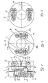
- the illustrated in Figure 1 embodiment of a coupling according to the invention consists of a first outer disc 1, a second outer disc 2 and a formed as a further disc spacer 3.
- the discs 1, 2 and the spacer 3 are circular cylindrical Formed rings which are mounted in the axial direction to each other.
- the two outer discs 1, 2 are as clamping discs, each with a radially continuous open slot, the slot width by means of a screw. 5 for the purpose of clamping on a shaft can be reduced.
- the second outer disc 2 introduced into the peripheral surface of the disc 2 holes 6, 7 recognizable for a screw head and the bolt.
- For the first Disk 1 is the hole 7 perpendicular to the drawing plane, so that only the front side of the bolt of the screw 5 can be seen.
- the handlebar consists of a in Longitudinally extending link body 9, at its two ends in each case one cylindrical attachment body 10, 11 is formed, wherein the two cylindrical attachment body 10, 11 in opposite axial directions from the handlebar body 9 protrude.
- each a cylindrical receptacle 12 and an adjoining chamber 13 form.
- the cylindrical receptacle 12 has a the board of the cylindrical Approaching body 10 on the handlebar body 9 corresponding greater depth.
- the depth the chamber 13 corresponds approximately to half the height of the handlebar body.
- Figure 1 reveals that such a cylindrical receptacle 12 and the thereto subsequent chamber 13 both in the center piece 3 facing surface of first disc 1 and in the opposite surface of the intermediate piece. 3 are arranged so that the recesses in the facing surfaces to accommodate the complete handlebar 8. Accordingly, the Arrangement of the cylindrical receptacle 12 and the chamber 13 in the first disc 1 directed opposite to the corresponding arrangement in the intermediate piece Be 3.
- Figure 2 is a section through two links 8 and a plan view of the cylindrical Recapture 12 and the chamber 13 recognize.
- the chamber 13 is, starting from the cylindrical receptacle 12 with flared side walls arranged 14a, 14b provided, between which the handlebar 8, as at the statedüegenden Ends shown with double arrows, perform a limited pivoting movement can.
- the cylindrical attachment body 11 is arranged, which with the intermediate piece 3 only rotatable, but not slidable to him, is stored, is the pivoting movement the link 8 with a parallel displacement of the intermediate piece 3 relative to the first disc 1 connected.
- Figure 3 illustrates that a completely analogous connection between the intermediate piece 3 and the second outer disc 2 is made, but the handlebar. 8 of the pair of handlebars between the outer pane 2 and the center piece 3 with respect to the Handlebars 8 of the link pair between the first outer disc 1 and the intermediate piece 3 are offset by a rotation angle of 90 ° to each other.
- 1, 2 identical components used as outer discs can be, which offset only in order to a rotation angle of 90 ° to each other Positions are mirror images of each other to be mounted on the intermediate piece 3.
- the Intermediate piece 3 differs from the outer discs 1, 2 in that cylindrical receptacles 12 and chambers 13 on both voids of the intermediate piece 3 (rotated by 90 ° to each other) are provided.
- the illustrated embodiment shows that one with very little axial length constructing coupling can be realized, the handlebar no axial mounting position beyond the three disks used 1-3. It is the Use of rigid arms 8 possible because the pivoting of the handlebars 8 from the storage of the cylindrical attachment body 10, 11 in the corresponding cylindrical receptacle 12 results so that a deformation of the handlebars not required it.
- the couplings according to the invention are therefore suitable for the transmission of large Torques.
Landscapes
- Engineering & Computer Science (AREA)
- General Engineering & Computer Science (AREA)
- Mechanical Engineering (AREA)
- Steering Devices For Bicycles And Motorcycles (AREA)
- Carriages For Children, Sleds, And Other Hand-Operated Vehicles (AREA)
- Non-Disconnectible Joints And Screw-Threaded Joints (AREA)
- Joints Allowing Movement (AREA)
- Mechanical Operated Clutches (AREA)
Abstract

Description
dass auf wenigstens einer der zueinander zeigenden Flächen eine durch eine Ausnehmung gebildete Kammer zur Aufnahme des Lenkerkörpers über wenigstens einen Teil seiner Höhe vorgesehen ist,
und dass die Breite der Kammer für eine begrenzte Schwenkbewegung des Lenkers dimensioniert ist.
- Figur 1
- eine Seitenansicht mit Teil-Schnittdarstellungen eines Ausführungsbeispiels einer erfindungsgemäßen Kupplung
- Figur 2
- einen Schnitt durch die Kupplung gemäß Figur 1 entlang der Linie A-B
- Figur 3
- einen Schnitt durch die Kupplung gemäß Figur 1 entlang der Linie C-D.
Claims (9)
- Kupplung zur drehfesten Verbindung von in einer Axialrichtung zu verbindenden umlaufenden Teilen, mit einer ersten äußeren Scheibe (1), die mit einem ersten umlaufenden Teil verbindbar ist, einer zweiten äußeren Scheibe (2), die mit einem zweiten umlaufenden Teil verbindbar ist, und mit einem Zwischenstück (3) das mit den beiden äußeren Scheiben (1, 2) über verschwenkbare Lenker (8) verbunden ist, dadurch gekennzeichnet, dass die Lenker jeweils einen sich über ihre Länge erstreckenden Lenkerkörper (9) und an den Enden jeweils einen Ansatzkörper (10, 11) aufweisen, die in entgegengesetzten axialen Richtungen vom Lenkerkörper (8) hervorstehen, dass die Ansatzkörper (10, 11) in entsprechende, durch Ausnehmungen gebildete Aufnahmen (12) in den zueinander zeigenden Flächen von Zwischenstück (3) und äußerer Scheibe (1, 2) eingesteckt sind, dass auf wenigstens einer der zueinander zeigenden Flächen eine durch eine Ausnehmung gebildete Kammer (13) zur Aufnahme des Lenkerkörpers (8) über wenigstens einen Teil seiner Höhe vorgesehen ist und dass die Breite der Kammer (13) für eine begrenzte Schwenkbewegung des Lenkers (8) dimensioniert ist.
- Kupplung nach Anspruch 1, dadurch gekennzeichnet, dass die Ansatzkörper (10, 11) und Aufnahmen (12) zylindrisch ausgebildet sind.
- Kupplung nach Anspruch 1, dadurch gekennzeichnet, dass die Ansatzkörper (10, 11) und Aufnahmen (12) kugelabschnittförmig ausgebildet sind.
- Kupplung nach einem der Ansprüche 1 bis 3, dadurch gekennzeichnet, dass in den zueinander zeigenden Flächen gleiche Aufnahmen (12) und Kammern (13) vorgesehen sind, die sich in entgegengesetzter Anordnung zur Aufnahme des Lenkers (8) ergänzen.
- Kupplung nach Anspruch 4, dadurch gekennzeichnet, dass die Kammern (13) eine etwa der halben Höhe des Lenkerkörpers (9) entsprechende Tiefe aufweisen.
- Kupplung nach einem der Ansprüche 1 bis 5, dadurch gekennzeichnet, dass die Kammern (13) Seitenwandungen (14a, 14b) aufweisen, die von der zylindrischen Aufnahme (12) aus leicht konisch erweitert zueinander verlaufen.
- Kupplung nach einem der Ansprüche 1 bis 6, dadurch gekennzeichnet, dass das Zwischenstück (3) auf seinen beiden Flächen jeweils ein Paar Kammern (13) und Aufnahmen (12) aufweist, die um einen Drehwinkel von 90° zueinander versetzt sind.
- Kupplung nach einem der Ansprüche 1 bis 7, dadurch gekennzeichnet, dass die Kammern (13) und Aufnahmen (12) eines Paares parallel und gleichgerichtet zueinander angeordnet sind.
- Kupplung nach einem der Ansprüche 1 bis 8, dadurch gekennzeichnet, dass das Zwischenstück (3) durch eine den Abmessungen der beiden äußeren Scheiben (1, 2) entsprechende weitere Scheibe gebildet ist.
Applications Claiming Priority (2)
| Application Number | Priority Date | Filing Date | Title |
|---|---|---|---|
| DE102004024467A DE102004024467B3 (de) | 2004-05-14 | 2004-05-14 | Kupplung zur drehfesten Verbindung von umlaufenden Teilen |
| DE102004024467 | 2004-05-14 |
Publications (3)
| Publication Number | Publication Date |
|---|---|
| EP1596083A2 true EP1596083A2 (de) | 2005-11-16 |
| EP1596083A3 EP1596083A3 (de) | 2005-11-23 |
| EP1596083B1 EP1596083B1 (de) | 2007-04-25 |
Family
ID=34936297
Family Applications (1)
| Application Number | Title | Priority Date | Filing Date |
|---|---|---|---|
| EP05010056A Expired - Lifetime EP1596083B1 (de) | 2004-05-14 | 2005-05-09 | Kupplung zur drehfesten Verbindung von umlaufenden Teilen |
Country Status (3)
| Country | Link |
|---|---|
| EP (1) | EP1596083B1 (de) |
| AT (1) | ATE360764T1 (de) |
| DE (2) | DE102004024467B3 (de) |
Cited By (1)
| Publication number | Priority date | Publication date | Assignee | Title |
|---|---|---|---|---|
| US10906145B2 (en) | 2017-01-05 | 2021-02-02 | American Axle & Manufacturing, Inc. | Driveline test fixture having compliant collar |
Family Cites Families (7)
| Publication number | Priority date | Publication date | Assignee | Title |
|---|---|---|---|---|
| GB463066A (en) * | 1935-09-21 | 1937-03-22 | Lewis Burn | Improvements in couplings for shafts or other rotatable members |
| DE839890C (de) * | 1950-06-10 | 1952-05-26 | Siemens Ag | Kupplung zweier Wellen |
| DE3151401A1 (de) * | 1981-12-24 | 1983-07-07 | Schmidt-Kupplung GmbH, 3340 Wolfenbüttel | Kupplung zum kuppeln umlaufender teile zum ausgleich von fluchtungsfehlern |
| DE3233736A1 (de) * | 1982-09-11 | 1984-03-15 | Schmidt-Kupplung GmbH, 3340 Wolfenbüttel | Lenkerlagerung fuer lenkergetriebe |
| DE3337714A1 (de) * | 1983-10-18 | 1985-04-25 | Schmidt-Kupplung GmbH, 3340 Wolfenbüttel | Wellenkupplung |
| DE3522487A1 (de) * | 1985-06-22 | 1987-01-02 | Schmidt Kupplung Gmbh | Kupplung zum kuppeln umlaufender maschinenteile |
| DE4403555C1 (de) * | 1994-02-04 | 1995-04-06 | Inkoma Maschinenbau Gmbh | Kupplung zum Kuppeln zweier umlaufender Teile |
-
2004
- 2004-05-14 DE DE102004024467A patent/DE102004024467B3/de not_active Expired - Fee Related
-
2005
- 2005-05-09 EP EP05010056A patent/EP1596083B1/de not_active Expired - Lifetime
- 2005-05-09 DE DE502005000619T patent/DE502005000619D1/de not_active Expired - Lifetime
- 2005-05-09 AT AT05010056T patent/ATE360764T1/de not_active IP Right Cessation
Cited By (1)
| Publication number | Priority date | Publication date | Assignee | Title |
|---|---|---|---|---|
| US10906145B2 (en) | 2017-01-05 | 2021-02-02 | American Axle & Manufacturing, Inc. | Driveline test fixture having compliant collar |
Also Published As
| Publication number | Publication date |
|---|---|
| DE502005000619D1 (de) | 2007-06-06 |
| DE102004024467B3 (de) | 2006-02-23 |
| ATE360764T1 (de) | 2007-05-15 |
| EP1596083A3 (de) | 2005-11-23 |
| EP1596083B1 (de) | 2007-04-25 |
Similar Documents
| Publication | Publication Date | Title |
|---|---|---|
| DE3427577C2 (de) | ||
| DE2355108C2 (de) | ||
| DE3007348A1 (de) | Wellenkupplung | |
| EP0175867B1 (de) | Kardanische Doppelkupplung | |
| EP0801241B1 (de) | Elastische, axial- und winkel-bewegliche Kupplung | |
| EP0121779A1 (de) | Ausgleichskupplung | |
| DE3109388A1 (de) | "hochelastische wellenkupplung" | |
| DE102004024467B3 (de) | Kupplung zur drehfesten Verbindung von umlaufenden Teilen | |
| DE3026756A1 (de) | Doppelachsantrib fuer drehgestelle von schienenfahrzeugen | |
| DE102009027855B3 (de) | Gleichlauf-Universalgelenk | |
| DE3710518C1 (de) | Drehgelenk fuer kleine Beugewinkel | |
| DE2924935C3 (de) | Elastische Wellenkupplung | |
| DE3036570C2 (de) | Wellenkupplung | |
| DE2504950A1 (de) | Gelenkkupplung | |
| DE3337714A1 (de) | Wellenkupplung | |
| DE4205653C2 (de) | Kreuzgelenk | |
| DE19748450C2 (de) | Kreuzgelenkwelle und Antriebsanordnung mit zwei Kreuzgelenkwellen | |
| CH627530A5 (en) | Device which couples two rotatable parts of a drive and permits misalignments of the coupled parts of the drive | |
| EP1691097B1 (de) | Isolierung für ein kardanisches Kreuzgelenk | |
| DE2451966A1 (de) | Kupplung zwischen zwei achsversetzten, rotierenden wellen | |
| DE3702799C2 (de) | ||
| EP1596082B1 (de) | Kupplung zur drehfesten Verbindung zweier umlaufender Teile | |
| EP1691096B1 (de) | Axiale Isolierung für ein kardanisches Kreuzgelenk | |
| DE684196C (de) | Reibraederwechselgetriebe | |
| DE3149471A1 (de) | Doppelachsantrieb fuer schienentriebfahrzeuge |
Legal Events
| Date | Code | Title | Description |
|---|---|---|---|
| PUAI | Public reference made under article 153(3) epc to a published international application that has entered the european phase |
Free format text: ORIGINAL CODE: 0009012 |
|
| PUAL | Search report despatched |
Free format text: ORIGINAL CODE: 0009013 |
|
| AK | Designated contracting states |
Kind code of ref document: A2 Designated state(s): AT BE BG CH CY CZ DE DK EE ES FI FR GB GR HU IE IS IT LI LT LU MC NL PL PT RO SE SI SK TR |
|
| AX | Request for extension of the european patent |
Extension state: AL BA HR LV MK YU |
|
| AK | Designated contracting states |
Kind code of ref document: A3 Designated state(s): AT BE BG CH CY CZ DE DK EE ES FI FR GB GR HU IE IS IT LI LT LU MC NL PL PT RO SE SI SK TR |
|
| AX | Request for extension of the european patent |
Extension state: AL BA HR LV MK YU |
|
| 17P | Request for examination filed |
Effective date: 20060422 |
|
| AKX | Designation fees paid |
Designated state(s): AT BE BG CH CY CZ DE DK EE ES FI FR GB GR HU IE IS IT LI LT LU MC NL PL PT RO SE SI SK TR |
|
| 17Q | First examination report despatched |
Effective date: 20060706 |
|
| GRAP | Despatch of communication of intention to grant a patent |
Free format text: ORIGINAL CODE: EPIDOSNIGR1 |
|
| GRAS | Grant fee paid |
Free format text: ORIGINAL CODE: EPIDOSNIGR3 |
|
| GRAA | (expected) grant |
Free format text: ORIGINAL CODE: 0009210 |
|
| AK | Designated contracting states |
Kind code of ref document: B1 Designated state(s): AT BE BG CH CY CZ DE DK EE ES FI FR GB GR HU IE IS IT LI LT LU MC NL PL PT RO SE SI SK TR |
|
| PG25 | Lapsed in a contracting state [announced via postgrant information from national office to epo] |
Ref country code: FI Free format text: LAPSE BECAUSE OF FAILURE TO SUBMIT A TRANSLATION OF THE DESCRIPTION OR TO PAY THE FEE WITHIN THE PRESCRIBED TIME-LIMIT Effective date: 20070425 |
|
| REG | Reference to a national code |
Ref country code: GB Ref legal event code: FG4D Free format text: NOT ENGLISH |
|
| REG | Reference to a national code |
Ref country code: IE Ref legal event code: FG4D Free format text: LANGUAGE OF EP DOCUMENT: GERMAN |
|
| REG | Reference to a national code |
Ref country code: CH Ref legal event code: EP |
|
| REF | Corresponds to: |
Ref document number: 502005000619 Country of ref document: DE Date of ref document: 20070606 Kind code of ref document: P |
|
| PG25 | Lapsed in a contracting state [announced via postgrant information from national office to epo] |
Ref country code: SE Free format text: LAPSE BECAUSE OF FAILURE TO SUBMIT A TRANSLATION OF THE DESCRIPTION OR TO PAY THE FEE WITHIN THE PRESCRIBED TIME-LIMIT Effective date: 20070725 |
|
| PG25 | Lapsed in a contracting state [announced via postgrant information from national office to epo] |
Ref country code: ES Free format text: LAPSE BECAUSE OF FAILURE TO SUBMIT A TRANSLATION OF THE DESCRIPTION OR TO PAY THE FEE WITHIN THE PRESCRIBED TIME-LIMIT Effective date: 20070805 |
|
| GBT | Gb: translation of ep patent filed (gb section 77(6)(a)/1977) |
Effective date: 20070718 |
|
| PG25 | Lapsed in a contracting state [announced via postgrant information from national office to epo] |
Ref country code: IS Free format text: LAPSE BECAUSE OF FAILURE TO SUBMIT A TRANSLATION OF THE DESCRIPTION OR TO PAY THE FEE WITHIN THE PRESCRIBED TIME-LIMIT Effective date: 20070825 |
|
| ET | Fr: translation filed | ||
| PG25 | Lapsed in a contracting state [announced via postgrant information from national office to epo] |
Ref country code: PT Free format text: LAPSE BECAUSE OF FAILURE TO SUBMIT A TRANSLATION OF THE DESCRIPTION OR TO PAY THE FEE WITHIN THE PRESCRIBED TIME-LIMIT Effective date: 20070925 |
|
| NLV1 | Nl: lapsed or annulled due to failure to fulfill the requirements of art. 29p and 29m of the patents act | ||
| PG25 | Lapsed in a contracting state [announced via postgrant information from national office to epo] |
Ref country code: PL Free format text: LAPSE BECAUSE OF FAILURE TO SUBMIT A TRANSLATION OF THE DESCRIPTION OR TO PAY THE FEE WITHIN THE PRESCRIBED TIME-LIMIT Effective date: 20070425 |
|
| REG | Reference to a national code |
Ref country code: IE Ref legal event code: FD4D |
|
| BERE | Be: lapsed |
Owner name: INKOMA MASCHINENBAU G.M.B.H. Effective date: 20070531 |
|
| PG25 | Lapsed in a contracting state [announced via postgrant information from national office to epo] |
Ref country code: CZ Free format text: LAPSE BECAUSE OF FAILURE TO SUBMIT A TRANSLATION OF THE DESCRIPTION OR TO PAY THE FEE WITHIN THE PRESCRIBED TIME-LIMIT Effective date: 20070425 Ref country code: DK Free format text: LAPSE BECAUSE OF FAILURE TO SUBMIT A TRANSLATION OF THE DESCRIPTION OR TO PAY THE FEE WITHIN THE PRESCRIBED TIME-LIMIT Effective date: 20070425 Ref country code: MC Free format text: LAPSE BECAUSE OF NON-PAYMENT OF DUE FEES Effective date: 20070531 Ref country code: NL Free format text: LAPSE BECAUSE OF FAILURE TO SUBMIT A TRANSLATION OF THE DESCRIPTION OR TO PAY THE FEE WITHIN THE PRESCRIBED TIME-LIMIT Effective date: 20070425 Ref country code: SI Free format text: LAPSE BECAUSE OF FAILURE TO SUBMIT A TRANSLATION OF THE DESCRIPTION OR TO PAY THE FEE WITHIN THE PRESCRIBED TIME-LIMIT Effective date: 20070425 Ref country code: BG Free format text: LAPSE BECAUSE OF FAILURE TO SUBMIT A TRANSLATION OF THE DESCRIPTION OR TO PAY THE FEE WITHIN THE PRESCRIBED TIME-LIMIT Effective date: 20070725 Ref country code: IE Free format text: LAPSE BECAUSE OF FAILURE TO SUBMIT A TRANSLATION OF THE DESCRIPTION OR TO PAY THE FEE WITHIN THE PRESCRIBED TIME-LIMIT Effective date: 20070425 |
|
| PG25 | Lapsed in a contracting state [announced via postgrant information from national office to epo] |
Ref country code: LT Free format text: LAPSE BECAUSE OF FAILURE TO SUBMIT A TRANSLATION OF THE DESCRIPTION OR TO PAY THE FEE WITHIN THE PRESCRIBED TIME-LIMIT Effective date: 20070425 Ref country code: SK Free format text: LAPSE BECAUSE OF FAILURE TO SUBMIT A TRANSLATION OF THE DESCRIPTION OR TO PAY THE FEE WITHIN THE PRESCRIBED TIME-LIMIT Effective date: 20070425 |
|
| PLBE | No opposition filed within time limit |
Free format text: ORIGINAL CODE: 0009261 |
|
| STAA | Information on the status of an ep patent application or granted ep patent |
Free format text: STATUS: NO OPPOSITION FILED WITHIN TIME LIMIT |
|
| PG25 | Lapsed in a contracting state [announced via postgrant information from national office to epo] |
Ref country code: BE Free format text: LAPSE BECAUSE OF NON-PAYMENT OF DUE FEES Effective date: 20070531 |
|
| 26N | No opposition filed |
Effective date: 20080128 |
|
| PG25 | Lapsed in a contracting state [announced via postgrant information from national office to epo] |
Ref country code: GR Free format text: LAPSE BECAUSE OF FAILURE TO SUBMIT A TRANSLATION OF THE DESCRIPTION OR TO PAY THE FEE WITHIN THE PRESCRIBED TIME-LIMIT Effective date: 20070726 |
|
| PGFP | Annual fee paid to national office [announced via postgrant information from national office to epo] |
Ref country code: FR Payment date: 20070525 Year of fee payment: 3 |
|
| PG25 | Lapsed in a contracting state [announced via postgrant information from national office to epo] |
Ref country code: RO Free format text: LAPSE BECAUSE OF FAILURE TO SUBMIT A TRANSLATION OF THE DESCRIPTION OR TO PAY THE FEE WITHIN THE PRESCRIBED TIME-LIMIT Effective date: 20070425 |
|
| PG25 | Lapsed in a contracting state [announced via postgrant information from national office to epo] |
Ref country code: AT Free format text: LAPSE BECAUSE OF NON-PAYMENT OF DUE FEES Effective date: 20070509 |
|
| PG25 | Lapsed in a contracting state [announced via postgrant information from national office to epo] |
Ref country code: EE Free format text: LAPSE BECAUSE OF FAILURE TO SUBMIT A TRANSLATION OF THE DESCRIPTION OR TO PAY THE FEE WITHIN THE PRESCRIBED TIME-LIMIT Effective date: 20070425 |
|
| REG | Reference to a national code |
Ref country code: FR Ref legal event code: ST Effective date: 20090119 |
|
| PG25 | Lapsed in a contracting state [announced via postgrant information from national office to epo] |
Ref country code: FR Free format text: LAPSE BECAUSE OF NON-PAYMENT OF DUE FEES Effective date: 20080602 |
|
| PG25 | Lapsed in a contracting state [announced via postgrant information from national office to epo] |
Ref country code: CY Free format text: LAPSE BECAUSE OF FAILURE TO SUBMIT A TRANSLATION OF THE DESCRIPTION OR TO PAY THE FEE WITHIN THE PRESCRIBED TIME-LIMIT Effective date: 20070425 |
|
| PG25 | Lapsed in a contracting state [announced via postgrant information from national office to epo] |
Ref country code: LU Free format text: LAPSE BECAUSE OF NON-PAYMENT OF DUE FEES Effective date: 20070509 |
|
| PG25 | Lapsed in a contracting state [announced via postgrant information from national office to epo] |
Ref country code: HU Free format text: LAPSE BECAUSE OF FAILURE TO SUBMIT A TRANSLATION OF THE DESCRIPTION OR TO PAY THE FEE WITHIN THE PRESCRIBED TIME-LIMIT Effective date: 20071026 Ref country code: TR Free format text: LAPSE BECAUSE OF FAILURE TO SUBMIT A TRANSLATION OF THE DESCRIPTION OR TO PAY THE FEE WITHIN THE PRESCRIBED TIME-LIMIT Effective date: 20070425 |
|
| REG | Reference to a national code |
Ref country code: CH Ref legal event code: PL |
|
| GBPC | Gb: european patent ceased through non-payment of renewal fee |
Effective date: 20090509 |
|
| PG25 | Lapsed in a contracting state [announced via postgrant information from national office to epo] |
Ref country code: LI Free format text: LAPSE BECAUSE OF NON-PAYMENT OF DUE FEES Effective date: 20090531 Ref country code: CH Free format text: LAPSE BECAUSE OF NON-PAYMENT OF DUE FEES Effective date: 20090531 |
|
| PG25 | Lapsed in a contracting state [announced via postgrant information from national office to epo] |
Ref country code: GB Free format text: LAPSE BECAUSE OF NON-PAYMENT OF DUE FEES Effective date: 20090509 |
|
| PGFP | Annual fee paid to national office [announced via postgrant information from national office to epo] |
Ref country code: IT Payment date: 20080531 Year of fee payment: 4 |
|
| REG | Reference to a national code |
Ref country code: DE Ref legal event code: R082 Ref document number: 502005000619 Country of ref document: DE Representative=s name: GRAMM, LINS & PARTNER PATENT- UND RECHTSANWAEL, DE |
|
| PGFP | Annual fee paid to national office [announced via postgrant information from national office to epo] |
Ref country code: DE Payment date: 20240530 Year of fee payment: 20 |
|
| REG | Reference to a national code |
Ref country code: DE Ref legal event code: R071 Ref document number: 502005000619 Country of ref document: DE |