EP1596106A1 - Kombinationsölring - Google Patents
Kombinationsölring Download PDFInfo
- Publication number
- EP1596106A1 EP1596106A1 EP04712672A EP04712672A EP1596106A1 EP 1596106 A1 EP1596106 A1 EP 1596106A1 EP 04712672 A EP04712672 A EP 04712672A EP 04712672 A EP04712672 A EP 04712672A EP 1596106 A1 EP1596106 A1 EP 1596106A1
- Authority
- EP
- European Patent Office
- Prior art keywords
- ring body
- oil
- oil ring
- peripheral groove
- coil expander
- Prior art date
- Legal status (The legal status is an assumption and is not a legal conclusion. Google has not performed a legal analysis and makes no representation as to the accuracy of the status listed.)
- Granted
Links
Images



Classifications
-
- F—MECHANICAL ENGINEERING; LIGHTING; HEATING; WEAPONS; BLASTING
- F16—ENGINEERING ELEMENTS AND UNITS; GENERAL MEASURES FOR PRODUCING AND MAINTAINING EFFECTIVE FUNCTIONING OF MACHINES OR INSTALLATIONS; THERMAL INSULATION IN GENERAL
- F16J—PISTONS; CYLINDERS; SEALINGS
- F16J9/00—Piston-rings, e.g. non-metallic piston-rings, seats therefor; Ring sealings of similar construction
- F16J9/06—Piston-rings, e.g. non-metallic piston-rings, seats therefor; Ring sealings of similar construction using separate springs or elastic elements expanding the rings; Springs therefor ; Expansion by wedging
- F16J9/061—Piston-rings, e.g. non-metallic piston-rings, seats therefor; Ring sealings of similar construction using separate springs or elastic elements expanding the rings; Springs therefor ; Expansion by wedging using metallic coiled or blade springs
- F16J9/062—Coiled spring along the entire circumference
-
- F—MECHANICAL ENGINEERING; LIGHTING; HEATING; WEAPONS; BLASTING
- F16—ENGINEERING ELEMENTS AND UNITS; GENERAL MEASURES FOR PRODUCING AND MAINTAINING EFFECTIVE FUNCTIONING OF MACHINES OR INSTALLATIONS; THERMAL INSULATION IN GENERAL
- F16J—PISTONS; CYLINDERS; SEALINGS
- F16J9/00—Piston-rings, e.g. non-metallic piston-rings, seats therefor; Ring sealings of similar construction
- F16J9/06—Piston-rings, e.g. non-metallic piston-rings, seats therefor; Ring sealings of similar construction using separate springs or elastic elements expanding the rings; Springs therefor ; Expansion by wedging
-
- F—MECHANICAL ENGINEERING; LIGHTING; HEATING; WEAPONS; BLASTING
- F02—COMBUSTION ENGINES; HOT-GAS OR COMBUSTION-PRODUCT ENGINE PLANTS
- F02F—CYLINDERS, PISTONS OR CASINGS, FOR COMBUSTION ENGINES; ARRANGEMENTS OF SEALINGS IN COMBUSTION ENGINES
- F02F5/00—Piston rings, e.g. associated with piston crown
Definitions
- the present invention relates to a combined oil control ring which is mounted on a piston of an internal combustion engine.
- a combined oil control ring having an approximately M-shaped cross section, which is configured such that upper and lower rails which bring outer peripheral surfaces thereof into slide contact with an inner surface of a cylinder and a web which connects the upper and lower rails and has a plurality of windows are integrally formed, is described in Japanese Unexamined Patent Publication Sho 61(1986)-45172 and Japanese Unexamined Patent Publication Hei 9(1997)-144881, for example.
- the combined oil control ring consists of an oil ring body 1 and a coil expander 2.
- the oil ring body 1 is an oil ring having an approximately M-shaped cross section in the radial direction which is formed of upper and lower rails 3, 4 and a web 5 which connects these rails 3, 4.
- Such a combined oil control ring is mounted in an oil ring groove 21 formed in a piston 20.
- Outer-peripheral protruding portions 6, 7 of the respective upper and lower rails 3, 4 have an approximately trapezoidal shape which is formed of outer peripheral slide surfaces 8, 9 which are brought into contact with a cylinder wall 22 and upper and lower inclined surfaces 10, 11 which are contiguous with the outer peripheral slide surfaces 8, 9.
- Side surfaces 12, 13 of the respective upper and lower rails 3, 4 face respective upper and lower surfaces 23, 24 of the ring groove of the piston.
- a lubricant which is scraped by the slide surfaces 8, 9 of the rails is allowed to move into an inner peripheral side of the oil ring body 1 from an outer peripheral groove 14 defined by the upper and lower rails 3, 4 and the web 5 through a large number of windows 25 formed in the web 5.
- the lubricant which is moved into an inner peripheral side of the oil ring groove 21 through the windows 25 is returned to an oil pan through an oil hole formed in the piston 20.
- inner peripheral surfaces 18, 19 of inner-peripheral protruding portions 15, 16 of the upper and lower rails 3, 4 have an arcuate shape and an inner peripheral groove 17 is formed of the inner-peripheral protruding portions 15, 16 and the web 5.
- the coil expander 2 is housed in the inner peripheral groove 17. By bringing the coil expander 2 and the arcuate surfaces 18, 19 of the inner peripheral groove 17 of the oil ring body 1 into contact with each other, the oil ring body 1 is pushed toward the cylinder wall 22.
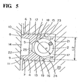
- the shape of the inner-peripheral protruding portions 15, 16 of the upper and lower rails 3, 4 may have a cross section of an approximately trapezoidal shape.
- the inner peripheral groove 17 is formed of the inner-peripheral protruding portions 15, 16 and the web 5.
- the coil expander 2 is housed in the inner peripheral groove 17. By bringing the coil expander 2 and tapered surfaces 18, 19 of the inner peripheral groove 17 formed in the oil ring body 1 into contact with each other, the oil ring body 1 is pushed toward to the cylinder wall 22.
- a maximum distance L2 in the axial direction between the inner-peripheral-groove arcuate surfaces 18, 19 or the inner-peripheral-groove tapered surfaces 18, 19 (see Fig. 5) of the oil ring body 1 is determined by a axial distance between inner peripheries 27' , 28' of the inner peripheral groove 17.
- the present invention has been made in view of the above-mentioned circumstances and it is an object of the present invention to provide a combined oil control ring which can prevent a coil expander from falling off an oil ring body at the time of mounting the combined oil control ring on the piston without losing functions of the oil ring such as oil scraping.
- the present invention provides a combined oil control ring which consists of an oil ring body which is formed of upper and lower rails which bring outer peripheral surfaces thereof into slide contact with an inner surface of a cylinder and a web 5 which connects the upper and lower rails and includes a plurality of windows, and a coil expander which pushes the oil ring body in the direction toward the inner surface of the cylinder, the coil expander being housed in an inner-peripheral groove of the oil ring body, wherein projecting portions which extend toward a center line in the thickness direction are formed at inner peripheral sides in the radial direction than a position where an axial distance between inner peripheries of an inner-peripheral groove portion of the oil ring body becomes maximum. Due to such a construction, when the oil control ring is mounted on the piston by widening an opening between but ends of the oil ring body, it is possible to prevent the coil expander housed in from falling off the oil ring body.
- L1 and L2 satisfy a relationship of 0.03 ⁇ (L2-L1)/L1 ⁇ 0.15.
- L1 means the minimum distance and L2 means the maximum distance.
- L1 and L2 satisfy a relationship of 0.05 ⁇ (L2-L1)/L1 ⁇ 0.10.
- (L2-L1)/L1 is smaller than 0.03, the remarkable falling-off prevention effect of coil expander cannot be recognized, while when (L2-L1)/L1 exceeds 0.15, it becomes difficult to insert the coil expander into the oil ring body.
- a coil diameter d of the coil expander and L1 of the oil ring body satisfy a relationship of 0. 2mm ⁇ L1-d ⁇ -0.10mm. So long as this relationship is satisfied, there is no possibility that the oil ring body leaves the deformation strain due to a force which is applied at the time of opening the inner peripheral ends of the oil ring in the axial direction in housing the coil expander in the oil ring body. Further, when an opening between the but ends of the oil ring body is widened in the peripheral direction at the time of mounting the oil ring on the piston, the coil expander hardly falls off the oil ring body.
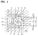
- a thickness of the oil ring body 1 is set as L3 and the inner peripheral portions 18, 19 of the inner-peripheral protruding portions 15, 16 of the upper and lower rails 3, 4 have an arcuate shape thus forming an inner-peripheral groove portion 26 which houses the coil expander 2.
- a width (distance) thereof in the axial direction expands while drawing arcs toward the radially inward direction in a vertical symmetry (an upper and lower symmetry) from a crossing point A1 of the inner-peripheral groove portion 26 and a thickness-direction center line (a line which passes the center of the width of the oil ring body 1) AA' and assumes a maximum value L2 at a line BB'.
- Projecting portions 27, 28 which extend toward the thickness-direction center line AA' are formed at positions disposed more inside in the radial direction than the line BB'. Due to the provision of these projecting portions 27, 28, it is possible to prevent the coil expander 2 from falling off at the time of mounting the combined oil control ring on the piston 20.
- the projecting portions 27, 28 are formed on open peripheries of the inner-peripheral groove portion 26 and a distance between the open peripheries in the axial direction assumes a minimum value L1 in inner position in the radial direction than the line BB'.
- the projecting portion is formed in inner position than the line BB', the position where the projecting portions are formed and define the minimum value L1 is not limited to the open peripheries.
- the projecting portions 27, 28 are formed in a vertical symmetry in the inner-peripheral groove portion 26 of the oil ring body 1 and ⁇ L1 and ⁇ L2 are set equal.
- the projecting portions 27, 28 have an approximately triangular cross section
- the shape of the projecting portions 27, 28 is not specifically limited.
- the peripheral ends of the projecting portions 27, 28 form an acute angle or are pointed, flattened portions may be formed on the ends of the projecting portions 27, 28 or the ends of the projecting portions 27, 28 may be rounded in view of manufacturing reasons and the prevention of fracture.
- the projecting portions 27, 28 may be formed on the whole periphery of the oil ring body 1, it is possible to prevent the coil expander from falling off even when the projecting portions 27, 28 are formed partially on the oil ring body in a circumferential direction. However, when the projecting portions 27, 28 are formed partially, it is necessary to take proper measures to suppress the occurrence of non-uniform face pressure of the oil ring.
- the inner-peripheral groove portion 26 is formed of upper and lower inclined surfaces 18, 19 and a vertical surface 30 which connects these inclined surfaces 18, 19. Further, both of the upper and lower groove portions form arcuate surfaces from a position slightly outside the line BB' along which the width of the inner-peripheral groove portion 26 assumes the maximum in the axial direction. Further, both of the upper and lower groove portions also form arcuate surfaces inside the line BB' independently from the arcuate surfaces outside the line BB'.
- the projecting portions 27, 28 having a cross section of an approximately triangular shape are formed on open peripheries.
- the oil ring body 1 having such a construction is also provided with the projecting portions 27, 28 and the position which sets the minimum size L1 in the axial direction of the inner-peripheral groove portion 26 is not always set at the open peripheries.
- the arcuate surfaces formed in Fig. 2 and the inner-peripheral groove portion 26 may adopt the configuration in which the projecting portions 27, 28 may be directly formed next to inclined surfaces 18, 19.
- the projecting portions 27, 28 are formed more gently and hence, it is desirable to form the arcuate surfaces as shown in Fig. 2.
- the construction shown in Fig. 3 is substantially equal to that of the embodiment shown in Fig. 1 except for a point that the projecting portion 28 is formed only on the lower portion and is not formed on the upper portion of the inner-peripheral groove portion 26.
- the coil expander 2 usually falls off downwardly and hence, the construction which forms the projecting portion 28 only on the lower portion of the inner-peripheral groove portion 26 also can prevent the coil expander from falling off.
- the projecting portion is formed only on the lower portion of the peripheral groove portion 26 in the drawing, with respect to the oil ring body 1 served in an actual operation, usually, there is no distinction between the upper portion and the lower portion and hence, the oil ring body 1 is mounted in a posture that a side of the oil ring body 1 where the projecting portion is formed is set as a lower side.
- ⁇ L1 and ⁇ L2 are not always required to have the same distance and the relationship between them may be set to ⁇ L1 > ⁇ L2 or ⁇ L1 ⁇ ⁇ L2.
- the coil expander 2 falls off toward the lower side and hence, when the maximum value L2 is fixed, the lower projecting portion 28 is formed larger than the upper projecting portion 27. That is, by setting the relationship between them to ⁇ L1 ⁇ ⁇ L2, it can be effectively achieved to prevent the coil expander 2 from falling off.
- “upper” and “lower” correspond to “upper” and “lower” at the time of mounting the combined oil control ring.
- a martensitic stainless steel wire having a cross section of oil ring body shown in Fig. 1 is wound around to define a bore diameter thus producing the oil ring body shown in Fig. 1.
- a tension Ft of the oil ring is set to 10N
- a nominal diameter is set to 75.0mm
- a radial thickness of the ring body is set to 1.5mm
- an axial width of the ring body is set to 1.5mm.
- the oil ring bodies which form the projecting portions 27, 28 in a vertical symmetry are manufactured such that inner peripheral groove space has the minimum distances L1 shown in Table 1 at the open peripheries.
- the oil rings shown in Fig. 4 are manufactured in the same manner as the example 1.
- a tension of the oil ring, a nominal diameter, a radial directional thickness and an axial width of the ring body are set to the same values as the example 1.
- This conventional ring is used as a comparison example.
- Coil expanders having a coil diameter d of 1.060mm are inserted into the oil ring body of the comparison example and the respective oil ring bodies of the examples 1 to 6.
- the mounting confirmation test is performed on whether or not the coil expander falls off the oil ring body in mounting the combined two-piece oil control ring on the piston.
- an opening between but ends of the oil ring body is widened to 16.5mm which is 11 times as large as 1.5mm which is the radial thickness of the oil ring body and, then, the oil ring is mounted in the oil ring groove of piston.
- the number of the oil rings which the coil expander falls off is decreased.
- the projecting portions such that a ratio of (L2-L1)/L1 assumes 0.03 or more, the remarkable falling-off prevention effect of the coil expander is observed.
- the ratio of (L2-L1)/L1 exceeds 0.15, it is difficult to insert the coil expander into the oil ring body.
- the oil ring bodies in which a tension Ft of the oil ring is set to 10N, a nominal diameter is set to 75.0mm, a radial thickness of the ring body is set to 1.5mm, and an axial width of the ring body is set to 1.5mm are produced.
- the widths of the upper and lower projecting portions are made different from each other such that ⁇ L1 assumes 0.028mm and ⁇ L2 assumes 0.052mm.
- the mounting confirmation test is performed in the same manner as the example 1 such that ⁇ L2 is disposed at the lower side. As a result, in 100 combined oil control rings tested, no falling off of the coil expander is recognized.
- the oil ring bodies shown in Fig. 3 are produced.
- no projecting portion is formed on the upper portion of the oil ring body so that ⁇ L1 assumes 0mm and the projecting portion is formed only on the lower portion of the oil ring body, wherein ⁇ L2 assumes 0.028mm.
- the projecting portions 27, 28 are formed in a vertical symmetry.
- the oil ring bodies shown in Fig. 1 are produced in the same manner as the example 1.
- the ends of the open peripheries are extended only in the radially inward direction and the thickness in the radial direction is set to 1.575mm which is 5% thicker than L3 (1.5mm) and, further, projecting portions are formed on the open peripheries in a vertical symmetry thus producing the oil ring body having L1 of 1.062mm.
- the oil ring body which has the radially extended thickness of 1.575mm and has no projecting portions is produced (comparison example 2).
- the coil expander having a coil diameter d of 1.060mm is combined with the respective obtained oil ring bodies.
- the mounting confirmation test is performed in the same manner as the example 1.
- the number of coil expander fallen off is 7 in 100 combined oil control rings tested, while with respect to the example 16, falling-off of the coil expander is not recognized.
- the present invention in mounting the oil ring on the piston by widening the opening between the but ends of the oil ring body of the combined oil control ring, it is possible to prevent the coil expander from falling off the oil ring body and hence, the combined oil control ring which enables the extremely easy assembly can be realized.
Landscapes
- Engineering & Computer Science (AREA)
- General Engineering & Computer Science (AREA)
- Mechanical Engineering (AREA)
- Chemical & Material Sciences (AREA)
- Combustion & Propulsion (AREA)
- Pistons, Piston Rings, And Cylinders (AREA)
Applications Claiming Priority (3)
| Application Number | Priority Date | Filing Date | Title |
|---|---|---|---|
| JP2003042515 | 2003-02-20 | ||
| JP2003042515 | 2003-02-20 | ||
| PCT/JP2004/001853 WO2004074717A1 (ja) | 2003-02-20 | 2004-02-19 | 組合せオイルリング |
Publications (3)
| Publication Number | Publication Date |
|---|---|
| EP1596106A1 true EP1596106A1 (de) | 2005-11-16 |
| EP1596106A4 EP1596106A4 (de) | 2006-02-08 |
| EP1596106B1 EP1596106B1 (de) | 2009-04-15 |
Family
ID=32905352
Family Applications (1)
| Application Number | Title | Priority Date | Filing Date |
|---|---|---|---|
| EP04712672A Expired - Lifetime EP1596106B1 (de) | 2003-02-20 | 2004-02-19 | Kombinierter ölabstreifring |
Country Status (8)
| Country | Link |
|---|---|
| US (1) | US7306233B2 (de) |
| EP (1) | EP1596106B1 (de) |
| JP (1) | JPWO2004074717A1 (de) |
| KR (1) | KR100669357B1 (de) |
| CN (1) | CN100561021C (de) |
| DE (1) | DE602004020592D1 (de) |
| TW (1) | TWI238233B (de) |
| WO (1) | WO2004074717A1 (de) |
Cited By (2)
| Publication number | Priority date | Publication date | Assignee | Title |
|---|---|---|---|---|
| DE102018114113A1 (de) * | 2018-06-13 | 2019-12-19 | Scherdel Innotec Forschungs- Und Entwicklungs-Gmbh | Ölabstreifring und Zylinderkolben mit einer Ölringnut und einem Ölabstreifring |
| WO2020216477A1 (de) * | 2019-04-24 | 2020-10-29 | Federal-Mogul Dresden, Zn Der Fmvv Gmbh | Zweiteiliger ölabstreifring mit vorteilhafter geometrie |
Families Citing this family (12)
| Publication number | Priority date | Publication date | Assignee | Title |
|---|---|---|---|---|
| US20070262533A1 (en) * | 2006-05-15 | 2007-11-15 | Wan-Chieh Lu | Scraper ring |
| JP4775269B2 (ja) * | 2007-01-10 | 2011-09-21 | トヨタ自動車株式会社 | 2ピース型のピストンリング |
| JP5557562B2 (ja) * | 2010-03-10 | 2014-07-23 | Tpr株式会社 | 組合せオイルリング |
| WO2011132679A1 (ja) * | 2010-04-19 | 2011-10-27 | 日本ピストンリング株式会社 | 内燃機関用オイルリング |
| JP5587285B2 (ja) | 2011-12-21 | 2014-09-10 | Tpr株式会社 | 組合せオイルリング |
| US20150240943A1 (en) * | 2012-09-28 | 2015-08-27 | G.B. Kirby Meacham | Reduced friction oil control piston rings |
| JP5980966B2 (ja) * | 2015-01-09 | 2016-08-31 | 株式会社リケン | 組合せオイルコントロールリング |
| JP6530200B2 (ja) * | 2015-02-23 | 2019-06-12 | 株式会社リケン | サイドレール |
| US10520085B2 (en) * | 2015-03-31 | 2019-12-31 | Nippon Piston Ring Co., Ltd. | Combined oil ring |
| DE102016110105B4 (de) * | 2016-06-01 | 2018-08-02 | Federal-Mogul Burscheid Gmbh | Kompressions-Ölabstreif-Kolbenring |
| EP3492781B1 (de) * | 2017-09-29 | 2022-11-23 | Tpr Co., Ltd. | Segment, kombinierter ölring und segmentherstellungsverfahren |
| JP6389970B1 (ja) * | 2018-01-16 | 2018-09-12 | Tpr株式会社 | 組合せオイルリング |
Family Cites Families (17)
| Publication number | Priority date | Publication date | Assignee | Title |
|---|---|---|---|---|
| US2087208A (en) * | 1934-01-17 | 1937-07-13 | William K Frielingsdorf | Piston ring |
| US2445090A (en) * | 1947-01-09 | 1948-07-13 | Perfect Circle Corp | Piston ring |
| GB1084389A (en) * | 1964-12-29 | 1967-09-20 | Rene Edmond Richard | Piston rings |
| BE691635A (de) * | 1966-01-27 | 1967-05-29 | ||
| FR1474049A (fr) * | 1966-01-27 | 1967-03-24 | Dispositif exerçant une poussée radiale pour segments de pistons | |
| JPS4510482Y1 (de) * | 1969-08-27 | 1970-05-14 | ||
| DE2205421A1 (de) | 1972-02-05 | 1973-08-09 | Braun Ag | Vorrichtung zum schutze des scherkopfes bei motorisch betriebenen trockenrasierapparaten |
| FR2183443A5 (de) * | 1971-11-30 | 1973-12-14 | Wellworthy Ltd | |
| JPS5966063U (ja) | 1982-10-26 | 1984-05-02 | 帝国ピストリング株式会社 | コイルエキスパンダ付オイルリング |
| JPS6069350U (ja) | 1983-10-20 | 1985-05-16 | いすゞ自動車株式会社 | オイルリング |
| JPH0721966Y2 (ja) | 1989-08-24 | 1995-05-17 | 帝国ピストンリング株式会社 | 組合せオイルリングのスペーサエキスパンダの合口重なり防止構造 |
| US5265890A (en) * | 1990-12-03 | 1993-11-30 | Peter J. Balsells | Seal with spring energizer |
| JPH08200500A (ja) | 1995-01-27 | 1996-08-06 | Nissan Motor Co Ltd | 組合せオイルリング |
| JP3266468B2 (ja) | 1995-07-27 | 2002-03-18 | 帝国ピストンリング株式会社 | 組合せオイルリングおよびそれとピストンとの組合せ |
| JPH0942451A (ja) | 1995-08-02 | 1997-02-14 | Teikoku Piston Ring Co Ltd | 組合せオイルリングおよびオイルリングの製造方法 |
| JPH09144881A (ja) | 1995-11-21 | 1997-06-03 | Teikoku Piston Ring Co Ltd | 組合せオイルリング |
| JP2003287128A (ja) | 2002-03-29 | 2003-10-10 | Nippon Piston Ring Co Ltd | 2ピース型組合せオイルリング |
-
2004
- 2004-02-18 TW TW093103926A patent/TWI238233B/zh not_active IP Right Cessation
- 2004-02-19 US US10/536,559 patent/US7306233B2/en not_active Expired - Fee Related
- 2004-02-19 CN CNB2004800016146A patent/CN100561021C/zh not_active Expired - Fee Related
- 2004-02-19 EP EP04712672A patent/EP1596106B1/de not_active Expired - Lifetime
- 2004-02-19 JP JP2005502752A patent/JPWO2004074717A1/ja active Pending
- 2004-02-19 WO PCT/JP2004/001853 patent/WO2004074717A1/ja not_active Ceased
- 2004-02-19 DE DE602004020592T patent/DE602004020592D1/de not_active Expired - Lifetime
- 2004-02-19 KR KR1020057010370A patent/KR100669357B1/ko not_active Expired - Fee Related
Cited By (4)
| Publication number | Priority date | Publication date | Assignee | Title |
|---|---|---|---|---|
| DE102018114113A1 (de) * | 2018-06-13 | 2019-12-19 | Scherdel Innotec Forschungs- Und Entwicklungs-Gmbh | Ölabstreifring und Zylinderkolben mit einer Ölringnut und einem Ölabstreifring |
| WO2020216477A1 (de) * | 2019-04-24 | 2020-10-29 | Federal-Mogul Dresden, Zn Der Fmvv Gmbh | Zweiteiliger ölabstreifring mit vorteilhafter geometrie |
| DE102019110583A1 (de) * | 2019-04-24 | 2020-10-29 | Federal-Mogul Dresden, ZN der FMVV GmbH mit Sitz in Burscheid | Zweiteiliger Ölabstreifring mit vorteilhafter Geometrie |
| DE102019110583B4 (de) | 2019-04-24 | 2021-12-23 | Federal-Mogul Dresden, ZN der FMVV GmbH mit Sitz in Burscheid | Zweiteiliger Ölabstreifring mit vorteilhafter Geometrie |
Also Published As
| Publication number | Publication date |
|---|---|
| WO2004074717A1 (ja) | 2004-09-02 |
| US20060027976A1 (en) | 2006-02-09 |
| JPWO2004074717A1 (ja) | 2006-06-01 |
| US7306233B2 (en) | 2007-12-11 |
| KR100669357B1 (ko) | 2007-01-16 |
| EP1596106B1 (de) | 2009-04-15 |
| EP1596106A4 (de) | 2006-02-08 |
| CN100561021C (zh) | 2009-11-18 |
| CN1717557A (zh) | 2006-01-04 |
| TW200424459A (en) | 2004-11-16 |
| TWI238233B (en) | 2005-08-21 |
| KR20050117516A (ko) | 2005-12-14 |
| DE602004020592D1 (de) | 2009-05-28 |
Similar Documents
| Publication | Publication Date | Title |
|---|---|---|
| EP1596106A1 (de) | Kombinationsölring | |
| KR100566234B1 (ko) | 사이드 레일 및 조합 오일제어링 | |
| JP6530200B2 (ja) | サイドレール | |
| EP0543515B1 (de) | Dreiteilige Ölabstreifringanordnung | |
| US4986168A (en) | Piston and multilayer piston ring set | |
| JP7254836B2 (ja) | 組合せオイルリング | |
| JP4382229B2 (ja) | 組合せオイルリング | |
| US4099730A (en) | Piston ring construction | |
| US4759266A (en) | Multiple part oil-control ring for piston | |
| EP4206498B1 (de) | Kombination aus kolbenringen und kombinierte struktur aus kolben und kolbenringen | |
| JP2019065830A (ja) | サイドレール | |
| US5651553A (en) | Antirotation structure for combined oil ring | |
| JP4856574B2 (ja) | 2ピースオイルリング用線材及び2ピースオイルリング | |
| US20020043769A1 (en) | Oil scraper piston ring having circumferentially distributed recesses | |
| US20080169612A1 (en) | Oil Ring for Internal Combustion Engine | |
| US12117084B2 (en) | Combination of piston rings, and combination structure of piston and piston rings | |
| KR102893535B1 (ko) | 오일 컨트롤 링 | |
| JP6978584B2 (ja) | 内燃機関のピストン及びその製造方法 | |
| JP2007170455A (ja) | 組合せオイルリング | |
| JP6438679B2 (ja) | オイルリング | |
| GB2192690A (en) | Piston oil control ring | |
| JP2007032777A (ja) | ピストンリング | |
| JP2008232378A (ja) | 2ピースオイルリング用線材 | |
| JPH07332156A (ja) | 内燃機関用ピストンの製造方法 | |
| JPH1113422A (ja) | 組立式カムシャフト |
Legal Events
| Date | Code | Title | Description |
|---|---|---|---|
| PUAI | Public reference made under article 153(3) epc to a published international application that has entered the european phase |
Free format text: ORIGINAL CODE: 0009012 |
|
| 17P | Request for examination filed |
Effective date: 20050524 |
|
| AK | Designated contracting states |
Kind code of ref document: A1 Designated state(s): AT BE BG CH CY CZ DE DK EE ES FI FR GB GR HU IE IT LI LU MC NL PT RO SE SI SK TR |
|
| AX | Request for extension of the european patent |
Extension state: AL LT LV MK |
|
| A4 | Supplementary search report drawn up and despatched |
Effective date: 20051228 |
|
| RBV | Designated contracting states (corrected) |
Designated state(s): DE FR GB |
|
| DAX | Request for extension of the european patent (deleted) | ||
| 17Q | First examination report despatched |
Effective date: 20060315 |
|
| GRAP | Despatch of communication of intention to grant a patent |
Free format text: ORIGINAL CODE: EPIDOSNIGR1 |
|
| GRAS | Grant fee paid |
Free format text: ORIGINAL CODE: EPIDOSNIGR3 |
|
| RTI1 | Title (correction) |
Free format text: COMBINATION OIL CONTROL RING |
|
| GRAA | (expected) grant |
Free format text: ORIGINAL CODE: 0009210 |
|
| AK | Designated contracting states |
Kind code of ref document: B1 Designated state(s): DE FR GB |
|
| REG | Reference to a national code |
Ref country code: GB Ref legal event code: FG4D |
|
| REF | Corresponds to: |
Ref document number: 602004020592 Country of ref document: DE Date of ref document: 20090528 Kind code of ref document: P |
|
| PLBE | No opposition filed within time limit |
Free format text: ORIGINAL CODE: 0009261 |
|
| STAA | Information on the status of an ep patent application or granted ep patent |
Free format text: STATUS: NO OPPOSITION FILED WITHIN TIME LIMIT |
|
| 26N | No opposition filed |
Effective date: 20100118 |
|
| GBPC | Gb: european patent ceased through non-payment of renewal fee |
Effective date: 20100219 |
|
| REG | Reference to a national code |
Ref country code: FR Ref legal event code: ST Effective date: 20101029 |
|
| PG25 | Lapsed in a contracting state [announced via postgrant information from national office to epo] |
Ref country code: FR Free format text: LAPSE BECAUSE OF NON-PAYMENT OF DUE FEES Effective date: 20100301 |
|
| PG25 | Lapsed in a contracting state [announced via postgrant information from national office to epo] |
Ref country code: GB Free format text: LAPSE BECAUSE OF NON-PAYMENT OF DUE FEES Effective date: 20100219 |
|
| PGFP | Annual fee paid to national office [announced via postgrant information from national office to epo] |
Ref country code: DE Payment date: 20160216 Year of fee payment: 13 |
|
| REG | Reference to a national code |
Ref country code: DE Ref legal event code: R119 Ref document number: 602004020592 Country of ref document: DE |
|
| PG25 | Lapsed in a contracting state [announced via postgrant information from national office to epo] |
Ref country code: DE Free format text: LAPSE BECAUSE OF NON-PAYMENT OF DUE FEES Effective date: 20170901 |