EP1596117A1 - Raccord entre un tuyau ondulé et une pièce de connection - Google Patents
Raccord entre un tuyau ondulé et une pièce de connection Download PDFInfo
- Publication number
- EP1596117A1 EP1596117A1 EP05009645A EP05009645A EP1596117A1 EP 1596117 A1 EP1596117 A1 EP 1596117A1 EP 05009645 A EP05009645 A EP 05009645A EP 05009645 A EP05009645 A EP 05009645A EP 1596117 A1 EP1596117 A1 EP 1596117A1
- Authority
- EP
- European Patent Office
- Prior art keywords
- sealing ring
- ring
- corrugated
- corrugated tube
- tube
- Prior art date
- Legal status (The legal status is an assumption and is not a legal conclusion. Google has not performed a legal analysis and makes no representation as to the accuracy of the status listed.)
- Withdrawn
Links
- 238000007789 sealing Methods 0.000 claims abstract description 40
- 238000006073 displacement reaction Methods 0.000 claims abstract description 6
- 239000002184 metal Substances 0.000 claims description 8
- 150000001875 compounds Chemical class 0.000 claims description 5
- OKTJSMMVPCPJKN-UHFFFAOYSA-N Carbon Chemical compound [C] OKTJSMMVPCPJKN-UHFFFAOYSA-N 0.000 claims description 3
- 229910002804 graphite Inorganic materials 0.000 claims description 3
- 239000010439 graphite Substances 0.000 claims description 3
- 230000004323 axial length Effects 0.000 claims description 2
- 239000000463 material Substances 0.000 claims description 2
- 239000013013 elastic material Substances 0.000 claims 1
- 230000006835 compression Effects 0.000 description 3
- 238000007906 compression Methods 0.000 description 3
- 239000000565 sealant Substances 0.000 description 2
- 230000004048 modification Effects 0.000 description 1
- 238000012986 modification Methods 0.000 description 1
- 238000012856 packing Methods 0.000 description 1
- 239000003566 sealing material Substances 0.000 description 1
- 238000003466 welding Methods 0.000 description 1
Images



Classifications
-
- F—MECHANICAL ENGINEERING; LIGHTING; HEATING; WEAPONS; BLASTING
- F16—ENGINEERING ELEMENTS AND UNITS; GENERAL MEASURES FOR PRODUCING AND MAINTAINING EFFECTIVE FUNCTIONING OF MACHINES OR INSTALLATIONS; THERMAL INSULATION IN GENERAL
- F16L—PIPES; JOINTS OR FITTINGS FOR PIPES; SUPPORTS FOR PIPES, CABLES OR PROTECTIVE TUBING; MEANS FOR THERMAL INSULATION IN GENERAL
- F16L25/00—Construction or details of pipe joints not provided for in, or of interest apart from, groups F16L13/00 - F16L23/00
- F16L25/0036—Joints for corrugated pipes
-
- F—MECHANICAL ENGINEERING; LIGHTING; HEATING; WEAPONS; BLASTING
- F16—ENGINEERING ELEMENTS AND UNITS; GENERAL MEASURES FOR PRODUCING AND MAINTAINING EFFECTIVE FUNCTIONING OF MACHINES OR INSTALLATIONS; THERMAL INSULATION IN GENERAL
- F16L—PIPES; JOINTS OR FITTINGS FOR PIPES; SUPPORTS FOR PIPES, CABLES OR PROTECTIVE TUBING; MEANS FOR THERMAL INSULATION IN GENERAL
- F16L33/00—Arrangements for connecting hoses to rigid members; Rigid hose-connectors, i.e. single members engaging both hoses
- F16L33/26—Arrangements for connecting hoses to rigid members; Rigid hose-connectors, i.e. single members engaging both hoses specially adapted for hoses made of metal
Definitions
- the invention relates to a connection between the end of a corrugated pipe and a fitting according to the preamble of claim 1.
- Corrugated tubes metal tubes that go through in continuous operation in great lengths Forming a deducted from a strip of metal strip to a pipe with Longitudinal slot, welding the longitudinal slot and subsequent waves made have a number of outstanding features, such as a good bendability, high transverse stiffness, etc.
- a disadvantage with corrugated metal pipes is that the connection to fittings because of the thin wall thickness of Tubing proves to be extremely difficult.
- For helically corrugated pipes Add to that the end face of the pipe is always eccentric to the tube longitudinal axis is located.
- a sealing packing for sealing corrugated pipes consisting of two arranged on the corrugated tube against each other and movable in one another sockets, between which a corrugated pipe comprehensive annulus is formed for receiving a sealant. It is a yourself provided on the inside of the sealing area corrugated tube sleeve.
- a sealant Graphite is proposed.
- the present invention is based on the object, the known compounds be improved so that they also for corrugated pipes with a nominal diameter of more than DN 80 are suitable.
- the particular advantage of the invention is the fact that by adjusting the Contour of the sealing ring to the contour of the corrugated pipe significantly shortens the overall lengths be and be considerably reduced by the small pressing surface, the pressing forces and a complete filling of the sealing chamber is ensured. This is the result desired seal ensured.
- FIG 1 is a section through a compound according to the teachings of the invention shown.
- FIG. 1 the end of a helically corrugated, thin-walled, longitudinally welded metal tube 1 shown, in which a support sleeve 2 with one of the corrugated shape matched coarse thread is screwed.
- a pressure ring 3 is adapted by means of a corrugated shape Grobgewindes unscrewed.
- the area 4c has at its free end to the At the end tapering tongue 4d on.
- a Sealing ring 6 is arranged in a through an end face and the inner wall of the pressure ring 3, an end face of the fitting 4, and a part of the corrugated tube 1 formed chamber 5 in a through an end face and the inner wall of the pressure ring 3, an end face of the fitting 4, and a part of the corrugated tube 1 formed chamber 5 in a through an end face and the inner wall of the pressure ring 3, an end face of the fitting 4, and a part of the corrugated tube 1 formed chamber 5 is arranged.
- the longitudinal axial displacement of the connector 4 can be done in many ways. So it is possible, for example, by an outside of the pressure ring 3 and the Connector attacking tool to press the sealing ring 6.
- FIG. 1 shows a further possibility.
- oblique bores 3b provided by which only one is shown.
- bolt 7 arranged on the end of a cone ring 8 is screwed.
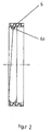
- FIG. 2 shows a section through a sealing ring 6.
- the sealing ring 6 indicates its inner surface has a helical corrugation 6a, which is adapted to the corrugation of the corrugated tube 1.
- the outer surface of the Seal 6 is smooth.
- the sealing ring 6 shown in Figure 2 can on the end of corrugated tube 1 are easily screwed on, as its inner surface a Air gap of a few tenths of a millimeter to the corrugated tube 1 has.
- Its outer diameter is also a few tenths of a millimeter lower than that Inner diameter of the part of the pressure ring 3, which the outer boundary of Chamber 5 forms.
- the conical tongue 4d penetrates of the area 4c in the sealing ring 6 and presses the sealing material in all existing Column.
- the sealing ring 6 As a material for the sealing ring 6, a special graphite is used, which has a density from 1.25 to 1.6 g / cm_. In the compressed state, the density is about 10 to 30% higher.
- the sealing ring 6 may be in a mold having a core whose outer surface having the corrugated profile can be produced. After completion of the core z. B. unscrewed and the sealing ring are removed from the mold.
- FIG. 3 shows a further embodiment in which, in a modification to FIG Area 4c of the connecting piece 4c and the adjacent parts of the support ring 2 and the Pressure ring 3 are adjusted accordingly.
- This embodiment allows a Sealing inside the corrugated pipe 1. This allows the outer dimensions of the Connection be reduced.
- FIG. 4 shows a further advantageous embodiment of a device according to the invention Connection.
- the connector 4 has at its end facing the corrugated tube 1 a lance-shaped extension 4e, which closely to the inner contour of the pressure ring. 3 rests and extends over the entire axial length of the sealing ring 6.
- the Wall thickness of extension 4e is between 1.2 and 5 mm.
Landscapes
- Engineering & Computer Science (AREA)
- General Engineering & Computer Science (AREA)
- Mechanical Engineering (AREA)
- Gasket Seals (AREA)
Applications Claiming Priority (2)
| Application Number | Priority Date | Filing Date | Title |
|---|---|---|---|
| DE202004007321U | 2004-05-07 | ||
| DE200420007321 DE202004007321U1 (de) | 2004-05-07 | 2004-05-07 | Verbindung zwischen dem Ende eines gewellten Rohres und einem Anschlußstück |
Publications (1)
| Publication Number | Publication Date |
|---|---|
| EP1596117A1 true EP1596117A1 (fr) | 2005-11-16 |
Family
ID=32842536
Family Applications (1)
| Application Number | Title | Priority Date | Filing Date |
|---|---|---|---|
| EP05009645A Withdrawn EP1596117A1 (fr) | 2004-05-07 | 2005-05-03 | Raccord entre un tuyau ondulé et une pièce de connection |
Country Status (2)
| Country | Link |
|---|---|
| EP (1) | EP1596117A1 (fr) |
| DE (1) | DE202004007321U1 (fr) |
Cited By (2)
| Publication number | Priority date | Publication date | Assignee | Title |
|---|---|---|---|---|
| US10781948B1 (en) | 2019-11-04 | 2020-09-22 | Trinity Bay Equipment Holdings, LLC | Pipe connector with annular communication |
| US11378207B2 (en) | 2019-11-22 | 2022-07-05 | Trinity Bay Equipment Holdings, LLC | Swaged pipe fitting systems and methods |
Families Citing this family (5)
| Publication number | Priority date | Publication date | Assignee | Title |
|---|---|---|---|---|
| EP1783413B1 (fr) | 2005-11-03 | 2011-10-12 | BRUGG Rohr AG, Holding | Dispositif pour raccorder les bouts d'un tuyau métallique ondulé hélicoïdalement avec un embout |
| DE102013111462A1 (de) * | 2013-10-17 | 2015-04-23 | Witzenmann Gmbh | Verbindung mit einem gewellten Schlauchleitungselement |
| DE102013112999A1 (de) * | 2013-11-25 | 2015-05-28 | Witzenmann Gmbh | Verbindung mit einem zumindest abschnittweise profilierten Schlauchleitungselement |
| DE102014105555A1 (de) | 2014-04-17 | 2015-10-22 | Brugg Rohr Ag, Holding | Anschlussverbindung für Wellrohre |
| US11204114B2 (en) | 2019-11-22 | 2021-12-21 | Trinity Bay Equipment Holdings, LLC | Reusable pipe fitting systems and methods |
Citations (10)
| Publication number | Priority date | Publication date | Assignee | Title |
|---|---|---|---|---|
| GB190903052A (en) * | 1909-02-08 | 1909-04-29 | Charles Rudolph | Improvements in Unions or Couplings for Flexible Metallic Pipes. |
| GB190922653A (en) * | 1909-10-05 | 1910-07-07 | Emil Witzenmann | An End Connection for Metallic Hose Pipes. |
| CH302253A (fr) * | 1949-07-01 | 1954-10-15 | Manuf Metallurg De La Jonchere | Tuyau flexible muni d'au moins un raccord. |
| FR1286787A (fr) * | 1961-01-24 | 1962-03-09 | Manuf De Caoutchouc Et D Eboni | Raccord pour tuyaux métalliques souples spiralés |
| DE3341297A1 (de) | 1983-11-15 | 1985-06-05 | Achim Dipl.-Ing. 3006 Burgwedel Daume | Verschraubungspackung |
| EP0545410A1 (fr) * | 1991-12-06 | 1993-06-09 | ASTROFLEX S.p.A. | Dispositif d'étanchéité pour un raccord rapide avec tuyaux non-tressés et flexibles en métal |
| EP0775865A1 (fr) | 1995-11-25 | 1997-05-28 | BRUGG Rohrsysteme GmbH | Dispositif de connexion de l'extrémité d'un tuyau ondulé en hélice à un raccord |
| US5857716A (en) * | 1997-02-07 | 1999-01-12 | Tru-Flex Metal Hose Corporation | Corrugated flexible hose coupling system |
| DE20113861U1 (de) | 2001-08-22 | 2002-01-24 | BRUGG Rohrsysteme GmbH, 31515 Wunstorf | Verbindung zwischen dem Ende eines schraubenlinienförmig gewellten Metallrohres mit einem Anschlußstück |
| DE10310938A1 (de) | 2003-03-13 | 2004-09-23 | Brugg Rohr Ag, Holding | Verfahren zur Herstellung einer Verbindung zwischen einem Wellrohr und einem Anschlußstück |
-
2004
- 2004-05-07 DE DE200420007321 patent/DE202004007321U1/de not_active Expired - Lifetime
-
2005
- 2005-05-03 EP EP05009645A patent/EP1596117A1/fr not_active Withdrawn
Patent Citations (10)
| Publication number | Priority date | Publication date | Assignee | Title |
|---|---|---|---|---|
| GB190903052A (en) * | 1909-02-08 | 1909-04-29 | Charles Rudolph | Improvements in Unions or Couplings for Flexible Metallic Pipes. |
| GB190922653A (en) * | 1909-10-05 | 1910-07-07 | Emil Witzenmann | An End Connection for Metallic Hose Pipes. |
| CH302253A (fr) * | 1949-07-01 | 1954-10-15 | Manuf Metallurg De La Jonchere | Tuyau flexible muni d'au moins un raccord. |
| FR1286787A (fr) * | 1961-01-24 | 1962-03-09 | Manuf De Caoutchouc Et D Eboni | Raccord pour tuyaux métalliques souples spiralés |
| DE3341297A1 (de) | 1983-11-15 | 1985-06-05 | Achim Dipl.-Ing. 3006 Burgwedel Daume | Verschraubungspackung |
| EP0545410A1 (fr) * | 1991-12-06 | 1993-06-09 | ASTROFLEX S.p.A. | Dispositif d'étanchéité pour un raccord rapide avec tuyaux non-tressés et flexibles en métal |
| EP0775865A1 (fr) | 1995-11-25 | 1997-05-28 | BRUGG Rohrsysteme GmbH | Dispositif de connexion de l'extrémité d'un tuyau ondulé en hélice à un raccord |
| US5857716A (en) * | 1997-02-07 | 1999-01-12 | Tru-Flex Metal Hose Corporation | Corrugated flexible hose coupling system |
| DE20113861U1 (de) | 2001-08-22 | 2002-01-24 | BRUGG Rohrsysteme GmbH, 31515 Wunstorf | Verbindung zwischen dem Ende eines schraubenlinienförmig gewellten Metallrohres mit einem Anschlußstück |
| DE10310938A1 (de) | 2003-03-13 | 2004-09-23 | Brugg Rohr Ag, Holding | Verfahren zur Herstellung einer Verbindung zwischen einem Wellrohr und einem Anschlußstück |
Cited By (2)
| Publication number | Priority date | Publication date | Assignee | Title |
|---|---|---|---|---|
| US10781948B1 (en) | 2019-11-04 | 2020-09-22 | Trinity Bay Equipment Holdings, LLC | Pipe connector with annular communication |
| US11378207B2 (en) | 2019-11-22 | 2022-07-05 | Trinity Bay Equipment Holdings, LLC | Swaged pipe fitting systems and methods |
Also Published As
| Publication number | Publication date |
|---|---|
| DE202004007321U1 (de) | 2004-08-05 |
Similar Documents
| Publication | Publication Date | Title |
|---|---|---|
| EP1457726B1 (fr) | Procédé d'établissement de liaison entre un tuyau ondulé et un raccord | |
| DE19740144C2 (de) | Verbindung eines Metallrohres mit einer Metallhülse, sowie Verfahren zur Herstellung der Verbindung | |
| DE102007025931B3 (de) | Klemmfitting für ein Rohr | |
| EP0925467B1 (fr) | Douille de fixation pour flexible | |
| DE4108741C2 (fr) | ||
| EP2153917A2 (fr) | Dispositif d'agrandissement pour tuyaux et raccord de serrage pour tuyaux | |
| DE102004052390A1 (de) | Pressverbindung mit multiplen Funktionen | |
| DE202004007321U1 (de) | Verbindung zwischen dem Ende eines gewellten Rohres und einem Anschlußstück | |
| EP1907742B1 (fr) | Tuyau souple et procede pour monter un ecrou d'accouplement sur un tuyau souple | |
| DE202007007827U1 (de) | Klemmfitting für ein Rohr | |
| EP1700059B1 (fr) | Raccord a compression pour tube ou tuyau | |
| DE19941577C2 (de) | Rohrverbindung und Verfahren zu ihrer Herstellung | |
| EP2682253B1 (fr) | Dispositif d'agrandissement et outil pour tuyaux d'installation | |
| EP2295842B1 (fr) | Raccord de tuyau destiné à raccorder de manière étanche une extrémité d'un tuyau en matière flexible | |
| DE19757946C2 (de) | Rohrverbindung | |
| EP2446980A2 (fr) | Tuyau et procédé destinés au traitement d'extrémités de tuyaux | |
| EP2457011B1 (fr) | Procédé pour relier une pièce de raccordement avec un conduit thermo-isolé | |
| DE102005060576B4 (de) | Wellrohrverschraubung/Anschlussverbindung | |
| CH692712A5 (de) | Verfahren zum Herstellen eines zugfesten Befestigungsanschlusses an einem Drahseil. | |
| DE102023107561A1 (de) | Rohrverbinder mit Halteeinrichtung | |
| DE9412445U1 (de) | Unlösbare Rohrverbindung | |
| DE3029621A1 (de) | Form- und nutvorrichtung fuer rohrenden | |
| DE29818534U1 (de) | Verbindung für Rohr- und/oder Schlauchleitungen | |
| DE8323074U1 (de) | Einrichtung zur Befestigung eines Rohres in einer Bohrung | |
| DE3047382A1 (de) | "rohrverbindung" |
Legal Events
| Date | Code | Title | Description |
|---|---|---|---|
| PUAI | Public reference made under article 153(3) epc to a published international application that has entered the european phase |
Free format text: ORIGINAL CODE: 0009012 |
|
| AK | Designated contracting states |
Kind code of ref document: A1 Designated state(s): AT BE BG CH CY CZ DE DK EE ES FI FR GB GR HU IE IS IT LI LT LU MC NL PL PT RO SE SI SK TR |
|
| AX | Request for extension of the european patent |
Extension state: AL BA HR LV MK YU |
|
| AKX | Designation fees paid |
Designated state(s): AT BE BG CH CY CZ DE DK EE ES FI FR GB GR HU IE IS IT LI LT LU MC NL PL PT RO SE SI SK TR |
|
| STAA | Information on the status of an ep patent application or granted ep patent |
Free format text: STATUS: THE APPLICATION IS DEEMED TO BE WITHDRAWN |
|
| 18D | Application deemed to be withdrawn |
Effective date: 20060517 |