EP1596151A1 - Arme à feu à répétition - Google Patents
Arme à feu à répétition Download PDFInfo
- Publication number
- EP1596151A1 EP1596151A1 EP05009545A EP05009545A EP1596151A1 EP 1596151 A1 EP1596151 A1 EP 1596151A1 EP 05009545 A EP05009545 A EP 05009545A EP 05009545 A EP05009545 A EP 05009545A EP 1596151 A1 EP1596151 A1 EP 1596151A1
- Authority
- EP
- European Patent Office
- Prior art keywords
- cartridge
- chamber
- weapon according
- closure head
- repeating
- Prior art date
- Legal status (The legal status is an assumption and is not a legal conclusion. Google has not performed a legal analysis and makes no representation as to the accuracy of the status listed.)
- Withdrawn
Links
- 230000006835 compression Effects 0.000 claims description 5
- 238000007906 compression Methods 0.000 claims description 5
- 230000035939 shock Effects 0.000 description 7
- 210000002105 tongue Anatomy 0.000 description 6
- 238000006073 displacement reaction Methods 0.000 description 4
- 230000008719 thickening Effects 0.000 description 4
- 230000006378 damage Effects 0.000 description 2
- 238000012360 testing method Methods 0.000 description 2
- 208000027418 Wounds and injury Diseases 0.000 description 1
- 230000005540 biological transmission Effects 0.000 description 1
- 230000000903 blocking effect Effects 0.000 description 1
- 230000001419 dependent effect Effects 0.000 description 1
- 238000011161 development Methods 0.000 description 1
- 230000018109 developmental process Effects 0.000 description 1
- 238000010304 firing Methods 0.000 description 1
- 208000014674 injury Diseases 0.000 description 1
- 238000003780 insertion Methods 0.000 description 1
- 230000037431 insertion Effects 0.000 description 1
- 230000001681 protective effect Effects 0.000 description 1
- 230000000284 resting effect Effects 0.000 description 1
Images


Classifications
-
- F—MECHANICAL ENGINEERING; LIGHTING; HEATING; WEAPONS; BLASTING
- F41—WEAPONS
- F41A—FUNCTIONAL FEATURES OR DETAILS COMMON TO BOTH SMALLARMS AND ORDNANCE, e.g. CANNONS; MOUNTINGS FOR SMALLARMS OR ORDNANCE
- F41A21/00—Barrels; Gun tubes; Muzzle attachments; Barrel mounting means
- F41A21/12—Cartridge chambers; Chamber liners
-
- F—MECHANICAL ENGINEERING; LIGHTING; HEATING; WEAPONS; BLASTING
- F41—WEAPONS
- F41A—FUNCTIONAL FEATURES OR DETAILS COMMON TO BOTH SMALLARMS AND ORDNANCE, e.g. CANNONS; MOUNTINGS FOR SMALLARMS OR ORDNANCE
- F41A15/00—Cartridge extractors, i.e. devices for pulling cartridges or cartridge cases at least partially out of the cartridge chamber; Cartridge ejectors, i.e. devices for throwing the extracted cartridges or cartridge cases free of the gun
- F41A15/12—Cartridge extractors, i.e. devices for pulling cartridges or cartridge cases at least partially out of the cartridge chamber; Cartridge ejectors, i.e. devices for throwing the extracted cartridges or cartridge cases free of the gun for bolt-action guns
- F41A15/14—Cartridge extractors, i.e. devices for pulling cartridges or cartridge cases at least partially out of the cartridge chamber; Cartridge ejectors, i.e. devices for throwing the extracted cartridges or cartridge cases free of the gun for bolt-action guns the ejector being mounted on or within the bolt; Extractors per se
Definitions
- the invention relates to a repeating weapon, in particular a repeating rifle, after Preamble of claim 1.
- Such a repeating weapon is known from DE 43 05 700 C1.
- By running as expansion sleeve Verrieglungshülse is with a Sp Schwarzkonus provided locking chamber locked in a closed position.
- cartridge chamber is usually designed so that the Sleeve bottom and the Auszieherrille the cartridge in the inserted state of the cartridge after protrude from the rear of the chamber.
- the lock chamber contains at its front End of a closure head with a front collar, which in the locked position of Locking chamber the end of the cartridge protruding from the chamber to the rear encloses. This provides protection against excessive gas pressure.
- the ring collar of the Locking head is dimensioned so that the security even at significantly excessive Gas pressure is guaranteed.
- the object of the invention is to provide a repeating weapon, which improved even more Safety against increased gas pressure has.
- the cartridge chamber is designed such that a Cartridge can be fully inserted into the cartridge chamber and that the Cartridge bearing a flush with the sleeve bottom of the cartridge flush rear End surface for planting a shock bottom of the chamber has.
- the cartridge is thus surrounded on its entire length on the outside of the stable chamber. Even the cartridge end, which is particularly susceptible to sleeve tears, is inside the cartridge bearing arranged, ensuring safety against sleeve tears and unexpectedly high gas pressure is improved.
- the cartridge chamber from a straight front surface of the Chamber be completed. At the closure head of the chamber no need separate protective sleeves or the like. Be provided.
- the cartridge extractor is in an advantageous embodiment in one lateral groove of the closure head projecting forward.
- the cartridge ejector is expediently in the form of a to the outer contour of the Locking head adapted plate with a front end face running in the Closing position flush with the shock bottom of the closure head.
- the Cartridge ejector is in an advantageous embodiment as a substantially U-shaped plate executed.
- the cartridge ejector can also be used as a circular, or annular be formed segment-like plate.
- the shock pad and the front face form one continuous flat end surface, through which the cartridge chamber to the rear is completed. Due to the special shape of the cartridge ejector is a clean Guiding the cartridge during insertion ensured and tilting of the sleeve during Ejecting prevented.
- the Verrieglungs is a through the Locking head of the chamber actuated locking sleeve with resilient Locking elements executed. But it could also be other locking devices Find use.
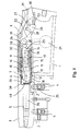
- the repeating rifle shown in part in FIGS. 1 and 2 contains a system box 1, on which a provided with fastening bolts 2 run 3 on fastening nuts 4 solvable is mounted. At the rear end of the system box 1 is not shown here Buttstock attachable.
- the barrel 3 contains at its rear end a cartridge chamber 5 and a locking head 6, on its inner wall a circumferential annular groove 7 for engagement a locking sleeve 8 contains.
- On the system box 1 is a designed as a slider Chamber holder 9 with a substantially cylindrical chamber 10 and the chamber 10th concentrically surrounding locking sleeve 8 in the longitudinal direction of the barrel 3 relative to Cartridge bearing 5 slidably guided.
- the locking sleeve 8 is designed as an expansion sleeve and contains at its front part a plurality of longitudinal slots divided by spring tongues 11, at its front end a thickening 12 for engagement in the annular groove 7 of the Have locking head 6.
- the locking sleeve 8 is at its rear end by means a crosspiece 13 is fixed within the chamber holder 9.
- the chamber 10 is axially within the locking sleeve 8 by a predetermined amount displaceable.
- the displacement is by the crosspiece 13 and one on the outside the chamber 10 provided groove 14 limited.
- the groove 14 is slightly wider than the crosspiece 13 whereby the relative displacement of chamber 10 and locking sleeve 8 allows becomes.
- a Striker 16 arranged with a firing pin spring 17.
- the chamber 10 has an enlarged diameter closure head 18 with a rear conical spreading surface 19, at which the spring tongues 11 of the Verrieglungshülse 8 with support their front end.
- a transverse bore of the chamber holder 9 is a transverse to the barrel axis shaft 20th a pivotable handle 21 mounted rotatably.
- the shaft 20 of the Chamber handle 21 is connected to a locking lever 22 which has a front hook 23rd for engaging in a lateral recess 24 at the rear end of the chamber 10 and a rear lug 25 for cooperation with a behind the locking lever 22nd arranged two-armed intermediate lever 26 has.
- the intermediate lever 26 is in the Chamber holder 9 mounted pivotably about a transverse axis 27. He contains one with the Lock lever 22 cooperating front lever arm 28 and a rear lever arm 29, which cooperates with a control plate 30.
- the shaft 20 also has a cam 31 is connected, which is used to move a in the Chamber holder 9 slidably guided in the direction and by a spring 32 to the rear acted release pin 33 is used.
- a cam 31 is connected, which is used to move a in the Chamber holder 9 slidably guided in the direction and by a spring 32 to the rear acted release pin 33 is used.
- the spring 32 so the chamber handle 21 in his in Figure 1 shown locking position pressed.
- the front end of the release pin 33 is located on the rear end face of the locking head 6.
- the cartridge chamber 5 is designed such that a Cartridge 34 can be fully inserted and a rear end surface 35 of the Cartridge is flush with the sleeve bottom 36 of the cartridge 34.
- the cartridge 34 is no longer with its sleeve bottom 36 from the cartridge chamber 5 backwards and is also enclosed in its Auszieherrille 37 of the chamber 5.
- In the back End surface 35 of the cartridge chamber 5 is only a small lateral recess 38 for Intervention of a cartridge extractor 39 shown in Figure 4 is provided.
- the chamber 10 shown separately in Figures 4 and 5 contains at her Closure head 18 has a lateral groove 40, in which the hook-shaped cartridge extractor 39th is arranged projecting forward.
- the groove 40 is opposite to the Closure head 18 also has a recess in the front view substantially U-shaped 41 for receiving a recess 41 in the matching cartridge ejector 42 is provided.
- the cartridge ejector 42 is in the form of a to the outer contour of the closure head 18th adapted, executed substantially U-shaped plate.
- the cartridge ejector 42 is arranged such that the cartridge extractor 39 is located between his legs.
- a bore 43 for receiving a guide pin 44 is introduced.
- the cartridge ejector 42 between a shown in Figure 4 Auswerfer ein and a shown in Figure 1 pushed back closed position movable.
- the bore 43 there are two more receiving holes 45 for each a compression spring 46, through which the cartridge ejector 42 in the ejector position is pressed.
- the cartridge ejector 42 is designed such that its Front end face 47 in the closed position flush with a front shock bottom 48 of the Chamber 10 completes. In the closed position so only through the groove 40th interrupted flat top surface reached.
- the cartridge extractor 39 is movable to the side via an inner projection 49 in the groove 40th guided the closure head 18. About a acted upon by a compression spring 50 Slider 51, the cartridge extractor 39 is held in the groove 40 and acted upon, a front hook piece 52 for engaging in the Auszieherrille 37 of a cartridge after inside is pressed.
- the chamber handle 21 is pivoted backwards, as shown in FIG.
- the cam 31 presses on the rear end of the Release pin 32, with its front end at the rear end 55 of the Locking head 6 is supported.
- the chamber holder 9 is thereby pushed backwards and Also takes the firmly associated with him locking sleeve 8, while the chamber 10th initially still in its forward position.
- the control plate 30 rotates the Between lever 26 in a clockwise direction until the rear lever arm 29 for resting on the Control plate 30 passes. Once the intermediate lever 26 through the control plate 30 completely has been turned up, the front lever arm 28 engages a recess of the rear Approach 25 of the locking lever 22, whereby the chamber handle 21 in the open Position is blocked.
- the invention described above is not limited to a repeating rifle. she can be used in a similar way for other repeating weapons.
Landscapes
- Engineering & Computer Science (AREA)
- General Engineering & Computer Science (AREA)
- Portable Nailing Machines And Staplers (AREA)
- Aiming, Guidance, Guns With A Light Source, Armor, Camouflage, And Targets (AREA)
- Toys (AREA)
- Telescopes (AREA)
Applications Claiming Priority (2)
| Application Number | Priority Date | Filing Date | Title |
|---|---|---|---|
| DE102004023555A DE102004023555B4 (de) | 2004-05-13 | 2004-05-13 | Repetierwaffe |
| DE102004023555 | 2004-05-13 |
Publications (1)
| Publication Number | Publication Date |
|---|---|
| EP1596151A1 true EP1596151A1 (fr) | 2005-11-16 |
Family
ID=34936015
Family Applications (1)
| Application Number | Title | Priority Date | Filing Date |
|---|---|---|---|
| EP05009545A Withdrawn EP1596151A1 (fr) | 2004-05-13 | 2005-04-30 | Arme à feu à répétition |
Country Status (6)
| Country | Link |
|---|---|
| US (1) | US7478494B2 (fr) |
| EP (1) | EP1596151A1 (fr) |
| DE (1) | DE102004023555B4 (fr) |
| NO (1) | NO330606B1 (fr) |
| RU (1) | RU2293276C1 (fr) |
| UA (1) | UA86004C2 (fr) |
Cited By (6)
| Publication number | Priority date | Publication date | Assignee | Title |
|---|---|---|---|---|
| WO2012097334A3 (fr) * | 2011-01-14 | 2013-08-15 | ArmWest, LLC | Arme à feu permettant un changement rapide du canon |
| US8813406B1 (en) | 2010-03-25 | 2014-08-26 | ArmWest, LLC | High capacity magazine with multiple springs |
| US8973483B2 (en) | 2010-03-25 | 2015-03-10 | Arm West, Llc | Gas regulator system |
| US9038525B2 (en) | 2011-01-14 | 2015-05-26 | ArmWest, LLC | Firearm |
| US9488423B2 (en) | 2011-01-14 | 2016-11-08 | Arm West, Llc | Firearm systems and methods |
| US10488136B2 (en) | 2016-09-23 | 2019-11-26 | ArmWest, LLC | Selective fire firearm systems and methods |
Families Citing this family (14)
| Publication number | Priority date | Publication date | Assignee | Title |
|---|---|---|---|---|
| DE102008027709A1 (de) * | 2008-06-11 | 2009-12-17 | Blaser Finanzholding Gmbh | Verschluss für ein Repetiergewehr und Systemkasten für einen derartigen Verschluss |
| DE202008007768U1 (de) * | 2008-06-11 | 2009-10-22 | Blaser Finanzholding Gmbh | Verschluss für ein Repetiergewehr und Lauf für einen derartigen Verschluss |
| US8826576B2 (en) | 2011-08-11 | 2014-09-09 | Karl R. Lewis | Firearm bolt |
| US9062926B2 (en) * | 2012-11-19 | 2015-06-23 | Apex Tactical Specialties, Inc. | Extractor for a firearm |
| DE102013003435B4 (de) | 2013-02-27 | 2014-10-16 | Heckler & Koch Gmbh | Ausstoßvorrichtung für eine Feuerwaffe sowie Waffengehäuse und Feuerwaffe mit einer Ausstoßvorrichtung |
| US9057572B2 (en) | 2013-03-15 | 2015-06-16 | Ra Brands, L.L.C. | Firearm extraction system |
| US8887426B2 (en) | 2013-03-15 | 2014-11-18 | Madison | Elastomeric extractor member |
| RU2538499C1 (ru) * | 2013-07-17 | 2015-01-10 | Борис Игоревич Хейфиц | Автоматическое огнестрельное оружие |
| US9562730B2 (en) | 2014-01-13 | 2017-02-07 | Ra Brands, L.L.C. | Replaceable feed ramp |
| DE102015108125A1 (de) * | 2015-05-22 | 2016-11-24 | L&O Hunting Group GmbH | Verschluss für ein Gewehr |
| US10254065B2 (en) * | 2016-10-31 | 2019-04-09 | General Dynamics Ordnance and Tactical Systems—Canada, Inc. | Systems and methods for a firearm conversion kit with slaved ejector |
| US11131530B2 (en) | 2018-01-29 | 2021-09-28 | Lawrence Livermore National Security, Llc | Opto-thermal laser detonator |
| US12215947B2 (en) | 2018-11-30 | 2025-02-04 | Theodore Karagias | Firearm bolt assembly with a pivoting handle |
| US11067347B2 (en) | 2018-11-30 | 2021-07-20 | Theodore Karagias | Firearm bolt assembly with a pivoting handle |
Citations (3)
| Publication number | Priority date | Publication date | Assignee | Title |
|---|---|---|---|---|
| US2226207A (en) * | 1938-07-22 | 1940-12-24 | Nomar Louis Nolan | Magazine rifle |
| FR865589A (fr) * | 1939-06-28 | 1941-05-27 | Smith And Wesson Inc | Arme à feu |
| US2845740A (en) * | 1954-12-02 | 1958-08-05 | Olin Mathieson | Integral barrel lock and extractor |
Family Cites Families (8)
| Publication number | Priority date | Publication date | Assignee | Title |
|---|---|---|---|---|
| DE358357C (de) * | 1919-10-15 | 1922-09-08 | Rheinische Metallw & Maschf | Selbsttaetige Feuerwaffe mit festem Lauf und fester Verriegelung |
| US1834410A (en) * | 1929-01-31 | 1931-12-01 | Remington Arms Co Inc | Firearm |
| US2811902A (en) * | 1952-01-18 | 1957-11-05 | Paul H Dixon | Mechanical bolt unlocking mechanism for recoiling barrel guns |
| DE7124565U (de) * | 1971-06-25 | 1971-11-18 | Anschuetz Jg Gmbh | Verschluss mit auszieher fuer feuerwaffen |
| FR2215600B1 (fr) * | 1973-01-29 | 1976-10-22 | Tellie Paul | |
| US4163334A (en) * | 1974-11-19 | 1979-08-07 | Ithaca Gun Company Incorporated | Firearm shell extractor |
| DE4305700C1 (de) * | 1993-02-25 | 1994-10-27 | Blaser Horst Jagdwaffen | Verschluß für eine Schußwaffe, insbesondere ein Repetiergewehr |
| ITMI20021016A1 (it) * | 2002-05-13 | 2003-11-13 | Beretta Armi Spa | Dispositivo di estrazione ed espulsione di un bossolo in un'arma da fuoco |
-
2004
- 2004-05-13 DE DE102004023555A patent/DE102004023555B4/de not_active Expired - Fee Related
-
2005
- 2005-04-30 EP EP05009545A patent/EP1596151A1/fr not_active Withdrawn
- 2005-05-04 NO NO20052187A patent/NO330606B1/no not_active IP Right Cessation
- 2005-05-05 RU RU2005113759/02A patent/RU2293276C1/ru not_active IP Right Cessation
- 2005-05-12 UA UAA200504439A patent/UA86004C2/ru unknown
- 2005-05-12 US US11/127,774 patent/US7478494B2/en not_active Expired - Fee Related
Patent Citations (3)
| Publication number | Priority date | Publication date | Assignee | Title |
|---|---|---|---|---|
| US2226207A (en) * | 1938-07-22 | 1940-12-24 | Nomar Louis Nolan | Magazine rifle |
| FR865589A (fr) * | 1939-06-28 | 1941-05-27 | Smith And Wesson Inc | Arme à feu |
| US2845740A (en) * | 1954-12-02 | 1958-08-05 | Olin Mathieson | Integral barrel lock and extractor |
Cited By (9)
| Publication number | Priority date | Publication date | Assignee | Title |
|---|---|---|---|---|
| US8813406B1 (en) | 2010-03-25 | 2014-08-26 | ArmWest, LLC | High capacity magazine with multiple springs |
| US8973483B2 (en) | 2010-03-25 | 2015-03-10 | Arm West, Llc | Gas regulator system |
| WO2012097334A3 (fr) * | 2011-01-14 | 2013-08-15 | ArmWest, LLC | Arme à feu permettant un changement rapide du canon |
| US9038525B2 (en) | 2011-01-14 | 2015-05-26 | ArmWest, LLC | Firearm |
| US9228786B2 (en) | 2011-01-14 | 2016-01-05 | ArmWest, LLC | Quick barrel change firearm |
| US9488423B2 (en) | 2011-01-14 | 2016-11-08 | Arm West, Llc | Firearm systems and methods |
| US11137222B2 (en) | 2011-01-14 | 2021-10-05 | ArmWest, LLC | Firearm systems and methods |
| US10488136B2 (en) | 2016-09-23 | 2019-11-26 | ArmWest, LLC | Selective fire firearm systems and methods |
| US11650023B2 (en) | 2016-09-23 | 2023-05-16 | Arm West, Llc | Selective fire firearm systems and methods |
Also Published As
| Publication number | Publication date |
|---|---|
| RU2293276C1 (ru) | 2007-02-10 |
| US20060090387A1 (en) | 2006-05-04 |
| NO20052187D0 (no) | 2005-05-04 |
| NO20052187L (no) | 2005-11-14 |
| UA86004C2 (en) | 2009-03-25 |
| US7478494B2 (en) | 2009-01-20 |
| RU2005113759A (ru) | 2006-11-20 |
| DE102004023555A1 (de) | 2005-12-08 |
| NO330606B1 (no) | 2011-05-23 |
| DE102004023555B4 (de) | 2008-07-24 |
Similar Documents
| Publication | Publication Date | Title |
|---|---|---|
| EP3011253B1 (fr) | Kit de conversion d'arme à feu ainsi que procédé de conversion d'une arme à feu | |
| EP1147359B1 (fr) | Culasse pour arme a feu de poing | |
| DE2019232C3 (de) | Verschlußeinrichtung für eine als Gasdrucklader ausgebildete Selbstladewaffe | |
| EP0890815B1 (fr) | Arme à feu portative comportant un dispositif à cartouche à blanc | |
| DE102004023555B4 (de) | Repetierwaffe | |
| DE102017002165B4 (de) | Gasabnahme und damit ausgestattetes Waffenrohr sowie Selbstladefeuerwaffe mit einer solchen Gasabnahme | |
| EP4038335B1 (fr) | Arme à feu dotée d'un éjecteur | |
| DE2402445A1 (de) | Vorrichtung zum verschwenkbaren seitlichen auswerfen fuer waffen | |
| EP3581872B1 (fr) | Culasse d'arme à répétition et arme à répétition dotée d'une telle culasse | |
| EP2133646B1 (fr) | Culasse pour fusils à répétition et canon pour une telle culasse | |
| CH627547A5 (de) | Patronenhuelsenauszieher fuer revolver. | |
| EP1147362B1 (fr) | Fixation de percuteur pour une arme de poing | |
| EP1379827B1 (fr) | Dispositif pour extraire des cartouches et/ou des douilles d'une arme a canon basculant | |
| EP3096107B1 (fr) | Mecanisme de culasse pour arme | |
| EP0437739B1 (fr) | Extracteur de cartouches | |
| DE102021005162B4 (de) | Gasabnahme | |
| EP4230950A1 (fr) | Culasse pour fusil à répétition | |
| DE202004007661U1 (de) | Repetierwaffe | |
| DE10051708B4 (de) | Selbstladepistole | |
| WO2012079657A1 (fr) | Support-percuteur pour une arme à feu portative | |
| EP3690381B1 (fr) | Arme à feu à fonction de répétition | |
| EP3581873B1 (fr) | Canon de fusil pourvu de guidage de cartouche intégré et arme à répétition dotée d'un tel canon de fusil | |
| DE69806317T2 (de) | Faustfeuerwaffe für Unschädlichmachungsgeschosse | |
| DE202016102404U1 (de) | Adapter, Kombination, Waffenlauf, Waffenlaufadapter und Waffensystem | |
| DE10021296B4 (de) | Vorrichtung zur Laufreduzierung für eine Schußwaffe sowie Adapterhülse für die Munition |
Legal Events
| Date | Code | Title | Description |
|---|---|---|---|
| PUAI | Public reference made under article 153(3) epc to a published international application that has entered the european phase |
Free format text: ORIGINAL CODE: 0009012 |
|
| AK | Designated contracting states |
Kind code of ref document: A1 Designated state(s): AT BE BG CH CY CZ DE DK EE ES FI FR GB GR HU IE IS IT LI LT LU MC NL PL PT RO SE SI SK TR |
|
| AX | Request for extension of the european patent |
Extension state: AL BA HR LV MK YU |
|
| 17P | Request for examination filed |
Effective date: 20060516 |
|
| AKX | Designation fees paid |
Designated state(s): AT BE BG CH CY CZ DE DK EE ES FI FR GB GR HU IE IS IT LI LT LU MC NL PL PT RO SE SI SK TR |
|
| 17Q | First examination report despatched |
Effective date: 20100113 |
|
| GRAP | Despatch of communication of intention to grant a patent |
Free format text: ORIGINAL CODE: EPIDOSNIGR1 |
|
| STAA | Information on the status of an ep patent application or granted ep patent |
Free format text: STATUS: THE APPLICATION IS DEEMED TO BE WITHDRAWN |
|
| 18D | Application deemed to be withdrawn |
Effective date: 20110322 |