EP1596164A1 - Automatische Zählerablesevorrichtung - Google Patents
Automatische Zählerablesevorrichtung Download PDFInfo
- Publication number
- EP1596164A1 EP1596164A1 EP04405297A EP04405297A EP1596164A1 EP 1596164 A1 EP1596164 A1 EP 1596164A1 EP 04405297 A EP04405297 A EP 04405297A EP 04405297 A EP04405297 A EP 04405297A EP 1596164 A1 EP1596164 A1 EP 1596164A1
- Authority
- EP
- European Patent Office
- Prior art keywords
- light
- image detector
- metering device
- light path
- window
- Prior art date
- Legal status (The legal status is an assumption and is not a legal conclusion. Google has not performed a legal analysis and makes no representation as to the accuracy of the status listed.)
- Granted
Links
Images

Classifications
-
- G—PHYSICS
- G01—MEASURING; TESTING
- G01D—MEASURING NOT SPECIALLY ADAPTED FOR A SPECIFIC VARIABLE; ARRANGEMENTS FOR MEASURING TWO OR MORE VARIABLES NOT COVERED IN A SINGLE OTHER SUBCLASS; TARIFF METERING APPARATUS; MEASURING OR TESTING NOT OTHERWISE PROVIDED FOR
- G01D4/00—Tariff metering apparatus
- G01D4/008—Modifications to installed utility meters to enable remote reading
-
- G—PHYSICS
- G06—COMPUTING OR CALCULATING; COUNTING
- G06M—COUNTING MECHANISMS; COUNTING OF OBJECTS NOT OTHERWISE PROVIDED FOR
- G06M1/00—Design features of general application
- G06M1/27—Design features of general application for representing the result of count in the form of electric signals, e.g. by sensing markings on the counter drum
- G06M1/272—Design features of general application for representing the result of count in the form of electric signals, e.g. by sensing markings on the counter drum using photoelectric means
-
- Y—GENERAL TAGGING OF NEW TECHNOLOGICAL DEVELOPMENTS; GENERAL TAGGING OF CROSS-SECTIONAL TECHNOLOGIES SPANNING OVER SEVERAL SECTIONS OF THE IPC; TECHNICAL SUBJECTS COVERED BY FORMER USPC CROSS-REFERENCE ART COLLECTIONS [XRACs] AND DIGESTS
- Y02—TECHNOLOGIES OR APPLICATIONS FOR MITIGATION OR ADAPTATION AGAINST CLIMATE CHANGE
- Y02B—CLIMATE CHANGE MITIGATION TECHNOLOGIES RELATED TO BUILDINGS, e.g. HOUSING, HOUSE APPLIANCES OR RELATED END-USER APPLICATIONS
- Y02B90/00—Enabling technologies or technologies with a potential or indirect contribution to GHG emissions mitigation
- Y02B90/20—Smart grids as enabling technology in buildings sector
-
- Y—GENERAL TAGGING OF NEW TECHNOLOGICAL DEVELOPMENTS; GENERAL TAGGING OF CROSS-SECTIONAL TECHNOLOGIES SPANNING OVER SEVERAL SECTIONS OF THE IPC; TECHNICAL SUBJECTS COVERED BY FORMER USPC CROSS-REFERENCE ART COLLECTIONS [XRACs] AND DIGESTS
- Y04—INFORMATION OR COMMUNICATION TECHNOLOGIES HAVING AN IMPACT ON OTHER TECHNOLOGY AREAS
- Y04S—SYSTEMS INTEGRATING TECHNOLOGIES RELATED TO POWER NETWORK OPERATION, COMMUNICATION OR INFORMATION TECHNOLOGIES FOR IMPROVING THE ELECTRICAL POWER GENERATION, TRANSMISSION, DISTRIBUTION, MANAGEMENT OR USAGE, i.e. SMART GRIDS
- Y04S20/00—Management or operation of end-user stationary applications or the last stages of power distribution; Controlling, monitoring or operating thereof
- Y04S20/30—Smart metering, e.g. specially adapted for remote reading
Definitions
- This invention relates to automatic meter reading, and especially to devices and methods for representing the result of count of a counting mechanism in the form of electric signals, using optoelectronic means.
- it relates to a device and a method for automatically monitoring a metering device.
- This invention is suited in a "retrofit” or “add-on” manner for all counting mechanisms such as electric-power meters, water meters or gas meters in industry or residential buildings.
- Reading the values from metering devices is of importance in various fields such as consumption of electric power, water, or gas in a facility, house, or apartment.
- the most frequent method to read the meters is to install a counting mechanism at the point of consumption and have a person taking the numbers from the meter roller from time to time.
- AMR automatic meter reading
- an automatic meter reader can work passively without any active illumination, relying just on the background light of the environment.
- counting mechanisms can be in various places as, e.g., in a dark basement illuminated merely by a light bulb, or also on the outside of a building. Therefore, an active and well-controlled illumination is necessary in practice. Possible solutions for such illuminations are known. Their light source are most practically light-emitting diodes (LEDs), but also laser diodes or thermal emitters could be employed.
- One of the major problems when using a semi-transparent mirror for concurrent visibility of the meter roller for a human observer is the light from outside that reaches the detector and sometimes disables a proper automatic reading.
- the environmental light can change considerably if, e.g., a light bulb is switched on in a dark basement or the sun light moves during the day.
- a lid covering the observer window is a possible solution, with the disadvantage that an automatic reading is not possible when a person is looking at the meter or if, accidentally or intentionally, the lid does not close completely.
- Another problem with automatic meter-reading devices is the specular back-reflection of light from the meter-housing window. This specular back-reflections from the plastic or glass surface is stronger than the diffuse back-scattering from the meter roller. Therefore, the bright reflexes can disable a proper reading of the numbers on the meter roller. Solving this problem by moving the light sources to larger angles, as proposed in WO-00/68643, is frequently not possible, because of the limited size of the meter reader. Furthermore, such a large angle illumination needs to be separately optimized for each type of meters as the distance from the front window to the roller can vary significantly. An illumination design not depending on the exact meter type is highly desirable.
- the disturbances of the automatic reading by background light of environment and/or the specular reflection of illumination on the meter-reader cover shall be suppressed or avoided.
- the illumination design shall not depend on the exact meter type.
- the inventive device for automatically monitoring a metering device comprises an image detector for detecting an image of said metering device, shielding means for shielding said image detector from at least part of light of environment, and/or anti-reflection means for preventing a direct reflection of illuminating light reaching said image detector.
- said metering device is imaged onto an image detector and detected by said image detector, said image detector is shielded from at least part of light of environment, and/or a direct reflection of illuminating light is prevented from reaching said image detector.
- a first improvement according to the present invention relates to the disturbance from background light. It protects the meter-reading device against external, undesired light sources, increases the illumination efficiency reflected by the semi-transparent mirror, and gives a brighter image to the human observer looking through the semitransparent mirror at the meter roller. This is achieved by using a different wavelength band of light for the detection system than for the human observer and using, consequently, wavelength-selective optical elements in the imaging path. Most practically, the automatic detection and illumination system operates in the near-infrared part of the spectrum, leaving the whole visible spectrum to the human observer.
- a first embodiment of the device further comprises a housing, a first window and a second window in said housing, a first light path within said housing for automatically monitoring said metering device, said first light path connecting said first window with said image detector, a second light path within said housing for visually monitoring said metering device, said second light path connecting said first window with said second window, and a light source for illuminating said metering device via said first window, said light source emitting light with a certain spectral characteristic.
- Said shielding means comprise optical wavelength-selective means, arranged in said first and/or second light path, which wavelength-selective means allow a first part of the electromagnetic spectrum which comprises at least one wavelength emitted by said light source to reach said image detector, and prevent a second, different part of the electromagnetic spectrum from reaching said image detector.
- said metering device is actively illuminated by light with a certain spectral characteristic, a first light path is provided for automatically monitoring said metering device with said image detector,and a second light path is provided for visually monitoring said metering device.
- a first part of the electromagnetic spectrum which comprises at least one wavelength comprised in said illuminating light is allowed to reach said image detector, and a second, different part of the electromagnetic spectrum is prevented from reaching said image detector.
- An alternative approach to obtain a similar improvement as with the two wavelength bands, is to use a fold-away mirror instead of the semi-transparent mirror.
- the fold-away mirror can be moved between two positions, with or without latching.
- the mirror can be turned either by the human observer or by an automatic actuation system.
- An example of a meter reader with manual actuation is an application where the default imaging path is directed to the image detector and a human observer has to turn and hold the mirror to see the meter roller.
- An example of a meter reader with an automatic actuation system is an application where the default imaging path is directed to the human observer and the meter reader flips the mirror temporarily to read the meter by the detection system.
- a second embodiment of the device further comprises a housing, a first window and a second window in said housing, a first light path within said housing for automatically monitoring said metering device, said first light path connecting said first window with said image detector, a second light path within said housing for visually monitoring said metering device, said second light path connecting said first window with said second window, and a light source for illuminating said metering device via said first window, said light source emitting light with a certain spectral characteristic.
- Said shielding means comprise a mirror movable between a first and a second position, which mirror in said first position releases said first light path and disables or blocks said second light path, and which mirror in said second position releases said second light path and disables or blocks said first light path.
- said metering device is actively illuminated by light with a certain spectral characteristic
- a first light path is provided for automatically monitoring said metering device with said image detector
- a second light path is provided for visually monitoring said metering device. Said first light path is released while said second light path is disabled or blocked, and said second light path is released while said first light path is disabled or blocked.
- a further improvement according to the invention concerns the undesired specular back-reflections on the meter window. It is based on a consecutive illumination and read-out of different areas of the meter.
- a third embodiment of the device according to the invention further comprises at least two light sources for illuminating said metering device, said light sources being locally separated from each other, wherein said anti-reflection means comprise means for separately switching on and off each of said light sources.
- said metering device is consecutively illuminated from at least two different directions, during each of said at least two illuminations, said metering device is imaged on an image detector and detected by said image detector, and at least two resulting image signals are used for obtaining an image of said metering device not disturbed by direct reflection of illuminating light.
- An alternative improvement according to the invention for reducing the undesired specular back-reflections uses two crossed polarizers.
- the illumination is polarized with a first polarizer, and a second polarizer (an analyzer) with perpendicular polarization direction is used to discriminate between the specular back-reflection on the window and the diffuse back-scattering on the meter roller.
- the reflected light on the meter window maintains its polarization state and is blocked by the "cross-polarized" analyzer in front of the detection system.
- the diffusively back-scattered light from the meter roller is partly depolarized and can pass the analyzer to a certain extent. The image on the detector is therefore undisturbed by any specular reflection.
- a fourth embodiment of the device according to the invention further comprises a light source for illuminating said metering device, wherein said anti-reflection means comprise polarizing means for linearly polarizing light emitted by said light source in a first polarization direction and analyzing means for linearly polarizing light impinging onto said image detector in a second polarization direction which is essentially perpendicular to said first polarization direction.
- said anti-reflection means comprise polarizing means for linearly polarizing light emitted by said light source in a first polarization direction and analyzing means for linearly polarizing light impinging onto said image detector in a second polarization direction which is essentially perpendicular to said first polarization direction.
- said metering device is illuminated by light linearly polarized in a first polarization direction, and only light linearly polarized in a second polarization direction which is essentially perpendicular to said first polarization direction is allowed to impinge onto said image detector.
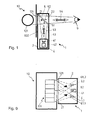
- a first embodiment of the reading device 1 according to the invention is shown in Figure 1.
- the reading device 1 serves for automatically monitoring one or more meter roller(s) 101 arranged in a meter housing 102 of a counting mechanism 10, and for simultaneously allowing a human observer 9 to see and read the meter roller(s) 101.
- the meter housing 102 has a transparent meter window 121 for observing the meter roller(s) 101.
- the reading device 1 comprises a reading housing 2 with a first reading window 21 and a second reading window 22.
- the reading housing 2 can be mounted on the meter housing 102 in such a way that the the meter window 121 and the first reading window 21 coincide or overlap.
- the embodiment shown in Fig. 1 uses two different wavelength bands 53, 54 for the automatic image-detection system and the human observer 9. It comprises a light source 3 for illumination of the meter roller(s) 101.
- the light source 3 is not shown in Fig. 1, but may be arranged inside the reading housing in front of or behind an image detector, in analogy to Figure 9.
- the light source 3 emits light in a first, limited spectral band 53, typically in the infrared part of the electromagnetic spectrum, towards a dichroic semi-transparent mirror 5.
- the light source 3 may be, e.g., an LED, a laser diode or a thermal source with a bandpass filter.
- An image detector 4 e.g., a solid-state image detector with a two-dimensional array of pixels, is arranged inside the reading housing 2.
- the image detector 4 serves for automatically reading the meter roller(s) 101.
- an imaging optical system 41 in the most simple case a lens, images the meter roller(s) 101 onto the detector plane.
- the image detector 4 converts the images into corresponding electric signals which may be read out via an output line (not shown).
- Suitable image detectors 4, output lines and devices for receiving, processing and interpreting output signals are known to persons skilled in the art.
- the reading device 1 further comprises a dichroic semi-transparent mirror 5 for separating the first spectral band 53 from a second, different spectral band 54, typically in the visible part of the electromagnetic spectrum.
- the dichroic mirror 5 reflects the first spectral band 53 stronger than transmitting it, and transmits the second spectral band 54 stronger than reflecting it.
- the separation can be either partial, which is achievable, e.g., with a metal-coated (e.g., Au-coated) transparent plate 5, or complete, which is achievable, e.g., with a dielectric-coated plate 5.
- the dichroic mirror 5 is arranged inside the reading housing 2 in such a way that it reflects light emitted by the light source 3 towards the meter roller(s) 101, and that it reflects light scattered by the meter roller(s) 101 towards the image detector 4.
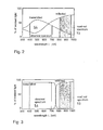
- Figure 2 shows the tansmission and reflection of a partly dichroic semitransparent mirror 5, and Figure 3 the transmission and reflection of a dichroic mirror with complete separation, versus the light wavelength ⁇ .
- the first spectral band 53 lies, e.g., between 800 and 950 nm and is used for the automatic reading by the image detector 4, whereas the second spectral band 54 lies, e.g., between 400 and 700 nm and is used for the visual reading by the observer 9.
- the dichroic mirror 5 transmits more light in the visible than the infrared leading to a brighter image for the observer 9.
- the dichroic mirror 5 reflects more light in the infrared than the visible, resulting in a better signal-to-noise ratio for the automatic reading system.
- the image detector 4, and possibly the lens 41, is placed in a shielding box 42 impenetrable for any light.
- Light within the first spectral band 53 can pass into and out of the shielding box 42 through a box window 43 which comprises, or is preferably designed as, a spectral (or color) filter.
- the filter 43 serves for shielding the image detector 4 from undesired reflected or scattered light from the second spectral band 54 that could disturb the automatic meter reading.
- the filter 43 can be placed in front of or behind the imaging lens 41.
- the filter 43 can also be included in the lens 41 itself by coloring the lens 41 accordingly.
- the image detector 4 can only receive light which passed through the filter 43.
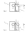
- a second embodiment of the reading device 1 according to the invention uses a fold-away mirror 5' which allows to switch between the light path 51 for automatic reading and the light path 52 for visual reading.
- An example of this second embodiment is shown in Figures 4 and 5. Elements corresponding to those of Fig. 1 are designated by the same reference signs, and some elements (such as the shielding box 42) are omitted for the sake of clarity.
- the fold-away mirror 5' can be pivoted between two different positions.
- Figure 4 shows the reading device 1 in a first state in which the folding mirror 5' is in a horizontal position and thus allowing the observer to see the meter roller(s) 101.
- Figure 5 shows the reading device 1 in a second state in which the folding mirror 5' is in a 45° position, thus allowing the meter roller(s) 101 to be imaged on the image detector 4 for automatic reading.
- the fold-away mirror 5' is pivotably hinged on an axis 55. It may be optionally latched in one and/or the other position. It can be pivoted manually by the human observer 9 or by an automatic actuation system (not shown).
- a third embodiment of the reading device 1 according to the invention allows to take two consecutive images to avoid the specular back-reflection from the window(s) 21, 121. It is described with reference to Figures 6-8. These figures show, for three different states of the reading device 1: (a) top views of the reading device 1 and (b) images taken by the image detector 4.
- the exemplified embodiment of Figs. 6-8 has two LEDs, i.e., a left LED 3.1 and a right LED 3.2, as light sources, but the reading device 1 could also have more LEDs or different types of light sources.
- the left LED 3.1 is switched on and illuminates the right area of the meter rollers 101.
- the specular reflection 31.1 shows up in the left part of the image leaving the right part undisturbed for detection (Fig. 7(b)).
- the right LED 3.2 is switched on and illuminates the left area of the meter rollers 101.
- the specular reflection 31.2 appears now in the right part of the image, leaving the left part undisturbed for detection (Fig. 8(b)).
- the two undisturbed half-images (Figs. 7(b) and 8(b)) have to be analyzed separately or can be combined to a single image for further processing.
- the sequence can, of course, also be first right and then left.
- Means for switching on and off the LEDs 3.1, 3.2 in a coordinated manner, for reading out parts of the images, for combining partial images etc. are known to a person skilled in the art and need not be described further here.
- Figure 9 shows a fourth embodiment of the device 1 according to the invention, which reduces the undesired specular back-reflections 31.1, 31.2 by means of two crossed polarizers 61.1, 61.2 and 62.
- the light 30 illuminating the meter rollers 101 is linearly polarized, e.g., by first polarizers 61.1, 61.2 placed behind the light sources 3.1, 3.2.
- a second polarizer (an analyzer) 62 with a polarization direction perpendicular to that of the first polarizers 61.1, 61.2 is used to discriminate between the specular back-reflection 31.1, 31.2 on the windows 21, 121 and the diffuse back-scattering on the meter rollers 101.
- the light reflected on the windows 21, 121 maintains its polarization state and is blocked by the "cross-polarized” analyzer 62 in front of the image detector 4.
- the light diffusively back-scattered from the meter rollers 101 is partly depolarized and can pass the analyzer 62 to a certain extent.
- the image on the detector 4 is therefore undisturbed by any specular reflection 31.1, 31.2.
Landscapes
- Physics & Mathematics (AREA)
- General Physics & Mathematics (AREA)
- Engineering & Computer Science (AREA)
- Theoretical Computer Science (AREA)
- Investigating Or Analysing Materials By Optical Means (AREA)
Priority Applications (3)
| Application Number | Priority Date | Filing Date | Title |
|---|---|---|---|
| EP04405297A EP1596164B1 (de) | 2004-05-10 | 2004-05-10 | Automatische Zählerablesevorrichtung |
| DE602004010371T DE602004010371T2 (de) | 2004-05-10 | 2004-05-10 | Automatische Zählerablesevorrichtung |
| PCT/CH2005/000262 WO2005108930A1 (en) | 2004-05-10 | 2005-05-10 | Automatic meter-reading device |
Applications Claiming Priority (1)
| Application Number | Priority Date | Filing Date | Title |
|---|---|---|---|
| EP04405297A EP1596164B1 (de) | 2004-05-10 | 2004-05-10 | Automatische Zählerablesevorrichtung |
Publications (2)
| Publication Number | Publication Date |
|---|---|
| EP1596164A1 true EP1596164A1 (de) | 2005-11-16 |
| EP1596164B1 EP1596164B1 (de) | 2007-11-28 |
Family
ID=34932105
Family Applications (1)
| Application Number | Title | Priority Date | Filing Date |
|---|---|---|---|
| EP04405297A Expired - Lifetime EP1596164B1 (de) | 2004-05-10 | 2004-05-10 | Automatische Zählerablesevorrichtung |
Country Status (3)
| Country | Link |
|---|---|
| EP (1) | EP1596164B1 (de) |
| DE (1) | DE602004010371T2 (de) |
| WO (1) | WO2005108930A1 (de) |
Cited By (8)
| Publication number | Priority date | Publication date | Assignee | Title |
|---|---|---|---|---|
| CN101013478B (zh) * | 2007-01-25 | 2010-09-08 | 孙小唐 | 机电一体化计数器的电子数值变换方法 |
| GB2496421A (en) * | 2011-11-11 | 2013-05-15 | Metermimic Ltd | An optical sensor or viewing system for automatic meter readers |
| DE202015101634U1 (de) | 2015-03-31 | 2015-06-15 | Techem Energy Services Gmbh | Verbrauchserfassungsgerät mit codierter Verbrauchsanzeige zur automatischen Ablesung |
| EP2950053A1 (de) * | 2014-05-26 | 2015-12-02 | Ecometering SES | Anordnung eines verbrauchszählers und einer sensorvorrichtung |
| FR3046458A1 (fr) * | 2015-12-30 | 2017-07-07 | Patrice Christian Philippe Charles Chevalier | Lecteur convertisseur transmetteur et procedes associes |
| GB2549446A (en) * | 2015-12-08 | 2017-10-25 | William Mort Hugh | Utility meter register optical reading device |
| WO2019081877A1 (en) * | 2017-10-24 | 2019-05-02 | Deer Technology Ltd | OPTICAL READER COUNTER REGISTER READER DEVICE |
| JPWO2021010464A1 (ja) * | 2019-07-17 | 2021-09-13 | アシオット株式会社 | メーター読取り装置、アタッチメント部材、及び遠隔検針システム |
Families Citing this family (4)
| Publication number | Priority date | Publication date | Assignee | Title |
|---|---|---|---|---|
| CN101900759B (zh) * | 2009-05-31 | 2012-05-02 | 上海金陵智能电表有限公司 | 电能表的数据记录及节电装置 |
| DE102010053017B8 (de) | 2010-12-02 | 2018-03-29 | Q-loud GmbH | Verfahren und Vorrichtung zur optischen Zeichenerkennung der Ziffern eines Zählerstands eines dezimalen Zählers |
| DE102010053019B8 (de) | 2010-12-02 | 2018-03-29 | Q-loud GmbH | Zählerstandlesegerät und Verfahren zum Positionieren eines Zählerstandlesegeräts |
| CN114979820B (zh) * | 2022-04-15 | 2024-06-25 | 深圳市安卫普科技有限公司 | 一种智能抄表装置、远程抄表方法及系统 |
Citations (4)
| Publication number | Priority date | Publication date | Assignee | Title |
|---|---|---|---|---|
| US4331402A (en) * | 1979-11-29 | 1982-05-25 | Olympus Optical Co., Ltd. | Single-lens reflex camera |
| US4680704A (en) * | 1984-12-28 | 1987-07-14 | Telemeter Corporation | Optical sensor apparatus and method for remotely monitoring a utility meter or the like |
| WO1990005426A1 (en) * | 1988-11-03 | 1990-05-17 | Pearpoint Limited | T.v. surveillance camera |
| GB2278471A (en) * | 1993-05-24 | 1994-11-30 | Landis & Gyr Energy Management | Reading meters |
Family Cites Families (2)
| Publication number | Priority date | Publication date | Assignee | Title |
|---|---|---|---|---|
| US3904293A (en) * | 1973-12-06 | 1975-09-09 | Sherman Gee | Optical method for surface texture measurement |
| WO2000068643A1 (de) * | 1999-05-10 | 2000-11-16 | Schroeter Michael | Verbrauchszähler und verfahren zum ablesen eines ortsfesten verbrauchszählers |
-
2004
- 2004-05-10 DE DE602004010371T patent/DE602004010371T2/de not_active Expired - Lifetime
- 2004-05-10 EP EP04405297A patent/EP1596164B1/de not_active Expired - Lifetime
-
2005
- 2005-05-10 WO PCT/CH2005/000262 patent/WO2005108930A1/en not_active Ceased
Patent Citations (4)
| Publication number | Priority date | Publication date | Assignee | Title |
|---|---|---|---|---|
| US4331402A (en) * | 1979-11-29 | 1982-05-25 | Olympus Optical Co., Ltd. | Single-lens reflex camera |
| US4680704A (en) * | 1984-12-28 | 1987-07-14 | Telemeter Corporation | Optical sensor apparatus and method for remotely monitoring a utility meter or the like |
| WO1990005426A1 (en) * | 1988-11-03 | 1990-05-17 | Pearpoint Limited | T.v. surveillance camera |
| GB2278471A (en) * | 1993-05-24 | 1994-11-30 | Landis & Gyr Energy Management | Reading meters |
Cited By (12)
| Publication number | Priority date | Publication date | Assignee | Title |
|---|---|---|---|---|
| CN101013478B (zh) * | 2007-01-25 | 2010-09-08 | 孙小唐 | 机电一体化计数器的电子数值变换方法 |
| GB2496421A (en) * | 2011-11-11 | 2013-05-15 | Metermimic Ltd | An optical sensor or viewing system for automatic meter readers |
| EP2950053A1 (de) * | 2014-05-26 | 2015-12-02 | Ecometering SES | Anordnung eines verbrauchszählers und einer sensorvorrichtung |
| NL2012883B1 (nl) * | 2014-05-26 | 2016-06-08 | Ecometering Ses | Samenstel van een verbruiksmeter en een sensorsamenstel. |
| DE202015101634U1 (de) | 2015-03-31 | 2015-06-15 | Techem Energy Services Gmbh | Verbrauchserfassungsgerät mit codierter Verbrauchsanzeige zur automatischen Ablesung |
| GB2549446A (en) * | 2015-12-08 | 2017-10-25 | William Mort Hugh | Utility meter register optical reading device |
| GB2549446B (en) * | 2015-12-08 | 2020-05-27 | William Mort Hugh | Utility meter register optical reading device |
| FR3046458A1 (fr) * | 2015-12-30 | 2017-07-07 | Patrice Christian Philippe Charles Chevalier | Lecteur convertisseur transmetteur et procedes associes |
| WO2019081877A1 (en) * | 2017-10-24 | 2019-05-02 | Deer Technology Ltd | OPTICAL READER COUNTER REGISTER READER DEVICE |
| US11747172B2 (en) | 2017-10-24 | 2023-09-05 | Deer Technology Ltd. | Utility meter register optical reading device |
| JPWO2021010464A1 (ja) * | 2019-07-17 | 2021-09-13 | アシオット株式会社 | メーター読取り装置、アタッチメント部材、及び遠隔検針システム |
| US12266025B2 (en) | 2019-07-17 | 2025-04-01 | Asiot Co., Ltd. | Meter reading device, attachment member, and remote meter reading system |
Also Published As
| Publication number | Publication date |
|---|---|
| DE602004010371D1 (de) | 2008-01-10 |
| DE602004010371T2 (de) | 2008-10-02 |
| EP1596164B1 (de) | 2007-11-28 |
| WO2005108930A1 (en) | 2005-11-17 |
Similar Documents
| Publication | Publication Date | Title |
|---|---|---|
| EP1596164B1 (de) | Automatische Zählerablesevorrichtung | |
| US5617076A (en) | System for detecting ice or snow on surface which specularly reflects light | |
| CN103412407B (zh) | 多谱段图像采集系统 | |
| CN103189823B (zh) | 交互式偏振保持投影显示器 | |
| CN101922966A (zh) | 测量照度、接近度以及色温的图像传感器 | |
| US20140354868A1 (en) | Portable hyperspectral imager | |
| US3961198A (en) | Visually alignable sensor wand which excludes unwanted light from a sensor system | |
| JP2012132861A (ja) | 光学測定装置 | |
| US20110058037A1 (en) | Fire detection device and method for fire detection | |
| US6566670B1 (en) | Method and system for guiding a web of moving material | |
| CN102971744A (zh) | 用于测量施加于物体的光学可变标志的光学特性的方法和设备 | |
| RU2008145499A (ru) | Оптическое измерительное устройство | |
| JP2007514219A (ja) | 紙幣検証装置のための反射式光学センサ | |
| CN102069077A (zh) | 一种激光分选物料装置 | |
| TR200003897T2 (tr) | Elyaf rengini sınıflandırma sistemi | |
| CN207964840U (zh) | 可实现荧光免疫层析定量检查的食品安全综合分析装置 | |
| JP4570145B2 (ja) | 位置検出平面外に撮像部を有する光学式位置検出装置 | |
| US12413308B2 (en) | System and method for optical communication | |
| CN204924927U (zh) | 便携式全光谱干化学食品安全快速分析仪 | |
| US20100200735A1 (en) | Optical reading system | |
| CN207351885U (zh) | 光谱获取装置、光谱强度的获取装置、光谱摄像模块和移动终端 | |
| KR102164507B1 (ko) | 컨테이너 | |
| WO2002085091A3 (en) | Camera with improved illuminator | |
| RU196117U1 (ru) | Устройство для обнаружения скрытых видеокамер | |
| KR20170139241A (ko) | 가시광선 및 적외선 동시 관측용 빔스플리터 및 이를 포함하는 동시 관측 장치 |
Legal Events
| Date | Code | Title | Description |
|---|---|---|---|
| PUAI | Public reference made under article 153(3) epc to a published international application that has entered the european phase |
Free format text: ORIGINAL CODE: 0009012 |
|
| AK | Designated contracting states |
Kind code of ref document: A1 Designated state(s): AT BE BG CH CY CZ DE DK EE ES FI FR GB GR HU IE IT LI LU MC NL PL PT RO SE SI SK TR |
|
| AX | Request for extension of the european patent |
Extension state: AL HR LT LV MK |
|
| 17P | Request for examination filed |
Effective date: 20060123 |
|
| AKX | Designation fees paid |
Designated state(s): AT BE BG CH CY CZ DE DK EE ES FI FR GB GR HU IE IT LI LU MC NL PL PT RO SE SI SK TR |
|
| GRAP | Despatch of communication of intention to grant a patent |
Free format text: ORIGINAL CODE: EPIDOSNIGR1 |
|
| GRAS | Grant fee paid |
Free format text: ORIGINAL CODE: EPIDOSNIGR3 |
|
| GRAA | (expected) grant |
Free format text: ORIGINAL CODE: 0009210 |
|
| AK | Designated contracting states |
Kind code of ref document: B1 Designated state(s): AT BE BG CH CY CZ DE DK EE ES FI FR GB GR HU IE IT LI LU MC NL PL PT RO SE SI SK TR |
|
| REG | Reference to a national code |
Ref country code: GB Ref legal event code: FG4D |
|
| REG | Reference to a national code |
Ref country code: IE Ref legal event code: FG4D |
|
| REG | Reference to a national code |
Ref country code: CH Ref legal event code: EP |
|
| REF | Corresponds to: |
Ref document number: 602004010371 Country of ref document: DE Date of ref document: 20080110 Kind code of ref document: P |
|
| REG | Reference to a national code |
Ref country code: CH Ref legal event code: NV Representative=s name: SCHNEIDER FELDMANN AG PATENT- UND MARKENANWAELTE |
|
| PG25 | Lapsed in a contracting state [announced via postgrant information from national office to epo] |
Ref country code: SE Free format text: LAPSE BECAUSE OF FAILURE TO SUBMIT A TRANSLATION OF THE DESCRIPTION OR TO PAY THE FEE WITHIN THE PRESCRIBED TIME-LIMIT Effective date: 20080228 Ref country code: NL Free format text: LAPSE BECAUSE OF FAILURE TO SUBMIT A TRANSLATION OF THE DESCRIPTION OR TO PAY THE FEE WITHIN THE PRESCRIBED TIME-LIMIT Effective date: 20071128 Ref country code: ES Free format text: LAPSE BECAUSE OF FAILURE TO SUBMIT A TRANSLATION OF THE DESCRIPTION OR TO PAY THE FEE WITHIN THE PRESCRIBED TIME-LIMIT Effective date: 20080311 |
|
| NLV1 | Nl: lapsed or annulled due to failure to fulfill the requirements of art. 29p and 29m of the patents act | ||
| PG25 | Lapsed in a contracting state [announced via postgrant information from national office to epo] |
Ref country code: SI Free format text: LAPSE BECAUSE OF FAILURE TO SUBMIT A TRANSLATION OF THE DESCRIPTION OR TO PAY THE FEE WITHIN THE PRESCRIBED TIME-LIMIT Effective date: 20071128 Ref country code: FI Free format text: LAPSE BECAUSE OF FAILURE TO SUBMIT A TRANSLATION OF THE DESCRIPTION OR TO PAY THE FEE WITHIN THE PRESCRIBED TIME-LIMIT Effective date: 20071128 Ref country code: BG Free format text: LAPSE BECAUSE OF FAILURE TO SUBMIT A TRANSLATION OF THE DESCRIPTION OR TO PAY THE FEE WITHIN THE PRESCRIBED TIME-LIMIT Effective date: 20080228 Ref country code: PL Free format text: LAPSE BECAUSE OF FAILURE TO SUBMIT A TRANSLATION OF THE DESCRIPTION OR TO PAY THE FEE WITHIN THE PRESCRIBED TIME-LIMIT Effective date: 20071128 |
|
| PG25 | Lapsed in a contracting state [announced via postgrant information from national office to epo] |
Ref country code: AT Free format text: LAPSE BECAUSE OF FAILURE TO SUBMIT A TRANSLATION OF THE DESCRIPTION OR TO PAY THE FEE WITHIN THE PRESCRIBED TIME-LIMIT Effective date: 20071128 |
|
| PG25 | Lapsed in a contracting state [announced via postgrant information from national office to epo] |
Ref country code: CZ Free format text: LAPSE BECAUSE OF FAILURE TO SUBMIT A TRANSLATION OF THE DESCRIPTION OR TO PAY THE FEE WITHIN THE PRESCRIBED TIME-LIMIT Effective date: 20071128 Ref country code: DK Free format text: LAPSE BECAUSE OF FAILURE TO SUBMIT A TRANSLATION OF THE DESCRIPTION OR TO PAY THE FEE WITHIN THE PRESCRIBED TIME-LIMIT Effective date: 20071128 |
|
| REG | Reference to a national code |
Ref country code: CH Ref legal event code: PUE Owner name: XEMTEC AG Free format text: CSEM CENTRE SUISSE D'ELECTRONIQUE ET DE MICROTECHNIQUE SA#RUE JAQUET-DROZ 1#2007 NEUCHATEL (CH) -TRANSFER TO- XEMTEC AG#GUETERSTRASSE 3#6060 SARNEN (CH) |
|
| ET | Fr: translation filed | ||
| REG | Reference to a national code |
Ref country code: GB Ref legal event code: 732E |
|
| PG25 | Lapsed in a contracting state [announced via postgrant information from national office to epo] |
Ref country code: BE Free format text: LAPSE BECAUSE OF FAILURE TO SUBMIT A TRANSLATION OF THE DESCRIPTION OR TO PAY THE FEE WITHIN THE PRESCRIBED TIME-LIMIT Effective date: 20071128 Ref country code: SK Free format text: LAPSE BECAUSE OF FAILURE TO SUBMIT A TRANSLATION OF THE DESCRIPTION OR TO PAY THE FEE WITHIN THE PRESCRIBED TIME-LIMIT Effective date: 20071128 Ref country code: RO Free format text: LAPSE BECAUSE OF FAILURE TO SUBMIT A TRANSLATION OF THE DESCRIPTION OR TO PAY THE FEE WITHIN THE PRESCRIBED TIME-LIMIT Effective date: 20071128 |
|
| PG25 | Lapsed in a contracting state [announced via postgrant information from national office to epo] |
Ref country code: PT Free format text: LAPSE BECAUSE OF FAILURE TO SUBMIT A TRANSLATION OF THE DESCRIPTION OR TO PAY THE FEE WITHIN THE PRESCRIBED TIME-LIMIT Effective date: 20080428 |
|
| PLBE | No opposition filed within time limit |
Free format text: ORIGINAL CODE: 0009261 |
|
| STAA | Information on the status of an ep patent application or granted ep patent |
Free format text: STATUS: NO OPPOSITION FILED WITHIN TIME LIMIT |
|
| 26N | No opposition filed |
Effective date: 20080829 |
|
| PG25 | Lapsed in a contracting state [announced via postgrant information from national office to epo] |
Ref country code: MC Free format text: LAPSE BECAUSE OF NON-PAYMENT OF DUE FEES Effective date: 20080531 |
|
| PG25 | Lapsed in a contracting state [announced via postgrant information from national office to epo] |
Ref country code: EE Free format text: LAPSE BECAUSE OF FAILURE TO SUBMIT A TRANSLATION OF THE DESCRIPTION OR TO PAY THE FEE WITHIN THE PRESCRIBED TIME-LIMIT Effective date: 20071128 Ref country code: GR Free format text: LAPSE BECAUSE OF FAILURE TO SUBMIT A TRANSLATION OF THE DESCRIPTION OR TO PAY THE FEE WITHIN THE PRESCRIBED TIME-LIMIT Effective date: 20080229 |
|
| REG | Reference to a national code |
Ref country code: FR Ref legal event code: TP |
|
| PG25 | Lapsed in a contracting state [announced via postgrant information from national office to epo] |
Ref country code: IE Free format text: LAPSE BECAUSE OF NON-PAYMENT OF DUE FEES Effective date: 20080512 |
|
| PG25 | Lapsed in a contracting state [announced via postgrant information from national office to epo] |
Ref country code: CY Free format text: LAPSE BECAUSE OF FAILURE TO SUBMIT A TRANSLATION OF THE DESCRIPTION OR TO PAY THE FEE WITHIN THE PRESCRIBED TIME-LIMIT Effective date: 20071128 |
|
| PG25 | Lapsed in a contracting state [announced via postgrant information from national office to epo] |
Ref country code: HU Free format text: LAPSE BECAUSE OF FAILURE TO SUBMIT A TRANSLATION OF THE DESCRIPTION OR TO PAY THE FEE WITHIN THE PRESCRIBED TIME-LIMIT Effective date: 20080529 Ref country code: LU Free format text: LAPSE BECAUSE OF NON-PAYMENT OF DUE FEES Effective date: 20080510 |
|
| PG25 | Lapsed in a contracting state [announced via postgrant information from national office to epo] |
Ref country code: TR Free format text: LAPSE BECAUSE OF FAILURE TO SUBMIT A TRANSLATION OF THE DESCRIPTION OR TO PAY THE FEE WITHIN THE PRESCRIBED TIME-LIMIT Effective date: 20071128 |
|
| REG | Reference to a national code |
Ref country code: FR Ref legal event code: PLFP Year of fee payment: 13 |
|
| REG | Reference to a national code |
Ref country code: FR Ref legal event code: PLFP Year of fee payment: 14 |
|
| PGFP | Annual fee paid to national office [announced via postgrant information from national office to epo] |
Ref country code: GB Payment date: 20170614 Year of fee payment: 14 Ref country code: FR Payment date: 20170628 Year of fee payment: 14 Ref country code: DE Payment date: 20170613 Year of fee payment: 14 |
|
| PGFP | Annual fee paid to national office [announced via postgrant information from national office to epo] |
Ref country code: IT Payment date: 20170620 Year of fee payment: 14 |
|
| PGFP | Annual fee paid to national office [announced via postgrant information from national office to epo] |
Ref country code: CH Payment date: 20170828 Year of fee payment: 14 |
|
| REG | Reference to a national code |
Ref country code: CH Ref legal event code: PCOW Free format text: NEW ADDRESS: RUE DU COLLEGE 26, 1815 CLARENS (CH) |
|
| REG | Reference to a national code |
Ref country code: DE Ref legal event code: R119 Ref document number: 602004010371 Country of ref document: DE |
|
| REG | Reference to a national code |
Ref country code: CH Ref legal event code: PL |
|
| GBPC | Gb: european patent ceased through non-payment of renewal fee |
Effective date: 20180510 |
|
| PG25 | Lapsed in a contracting state [announced via postgrant information from national office to epo] |
Ref country code: LI Free format text: LAPSE BECAUSE OF NON-PAYMENT OF DUE FEES Effective date: 20180531 Ref country code: CH Free format text: LAPSE BECAUSE OF NON-PAYMENT OF DUE FEES Effective date: 20180531 |
|
| PG25 | Lapsed in a contracting state [announced via postgrant information from national office to epo] |
Ref country code: IT Free format text: LAPSE BECAUSE OF NON-PAYMENT OF DUE FEES Effective date: 20180510 Ref country code: GB Free format text: LAPSE BECAUSE OF NON-PAYMENT OF DUE FEES Effective date: 20180510 Ref country code: FR Free format text: LAPSE BECAUSE OF NON-PAYMENT OF DUE FEES Effective date: 20180531 Ref country code: DE Free format text: LAPSE BECAUSE OF NON-PAYMENT OF DUE FEES Effective date: 20181201 |