EP1596228A1 - Système d'éclairage avec conversion de polarisation optique - Google Patents
Système d'éclairage avec conversion de polarisation optique Download PDFInfo
- Publication number
- EP1596228A1 EP1596228A1 EP05008321A EP05008321A EP1596228A1 EP 1596228 A1 EP1596228 A1 EP 1596228A1 EP 05008321 A EP05008321 A EP 05008321A EP 05008321 A EP05008321 A EP 05008321A EP 1596228 A1 EP1596228 A1 EP 1596228A1
- Authority
- EP
- European Patent Office
- Prior art keywords
- light
- polarization
- regions
- region
- dark
- Prior art date
- Legal status (The legal status is an assumption and is not a legal conclusion. Google has not performed a legal analysis and makes no representation as to the accuracy of the status listed.)
- Granted
Links
Images


Classifications
-
- G—PHYSICS
- G02—OPTICS
- G02B—OPTICAL ELEMENTS, SYSTEMS OR APPARATUS
- G02B27/00—Optical systems or apparatus not provided for by any of the groups G02B1/00 - G02B26/00, G02B30/00
- G02B27/28—Optical systems or apparatus not provided for by any of the groups G02B1/00 - G02B26/00, G02B30/00 for polarising
- G02B27/283—Optical systems or apparatus not provided for by any of the groups G02B1/00 - G02B26/00, G02B30/00 for polarising used for beam splitting or combining
- G02B27/285—Optical systems or apparatus not provided for by any of the groups G02B1/00 - G02B26/00, G02B30/00 for polarising used for beam splitting or combining comprising arrays of elements, e.g. microprisms
-
- G—PHYSICS
- G03—PHOTOGRAPHY; CINEMATOGRAPHY; ANALOGOUS TECHNIQUES USING WAVES OTHER THAN OPTICAL WAVES; ELECTROGRAPHY; HOLOGRAPHY
- G03B—APPARATUS OR ARRANGEMENTS FOR TAKING PHOTOGRAPHS OR FOR PROJECTING OR VIEWING THEM; APPARATUS OR ARRANGEMENTS EMPLOYING ANALOGOUS TECHNIQUES USING WAVES OTHER THAN OPTICAL WAVES; ACCESSORIES THEREFOR
- G03B21/00—Projectors or projection-type viewers; Accessories therefor
- G03B21/14—Details
- G03B21/20—Lamp housings
- G03B21/2073—Polarisers in the lamp house
-
- H—ELECTRICITY
- H04—ELECTRIC COMMUNICATION TECHNIQUE
- H04N—PICTORIAL COMMUNICATION, e.g. TELEVISION
- H04N5/00—Details of television systems
- H04N5/74—Projection arrangements for image reproduction, e.g. using eidophor
-
- H—ELECTRICITY
- H04—ELECTRIC COMMUNICATION TECHNIQUE
- H04N—PICTORIAL COMMUNICATION, e.g. TELEVISION
- H04N9/00—Details of colour television systems
- H04N9/12—Picture reproducers
- H04N9/31—Projection devices for colour picture display, e.g. using electronic spatial light modulators [ESLM]
- H04N9/3141—Constructional details thereof
- H04N9/315—Modulator illumination systems
- H04N9/3167—Modulator illumination systems for polarizing the light beam
-
- H—ELECTRICITY
- H04—ELECTRIC COMMUNICATION TECHNIQUE
- H04N—PICTORIAL COMMUNICATION, e.g. TELEVISION
- H04N5/00—Details of television systems
- H04N5/74—Projection arrangements for image reproduction, e.g. using eidophor
- H04N5/7416—Projection arrangements for image reproduction, e.g. using eidophor involving the use of a spatial light modulator, e.g. a light valve, controlled by a video signal
- H04N5/7441—Projection arrangements for image reproduction, e.g. using eidophor involving the use of a spatial light modulator, e.g. a light valve, controlled by a video signal the modulator being an array of liquid crystal cells
-
- Y—GENERAL TAGGING OF NEW TECHNOLOGICAL DEVELOPMENTS; GENERAL TAGGING OF CROSS-SECTIONAL TECHNOLOGIES SPANNING OVER SEVERAL SECTIONS OF THE IPC; TECHNICAL SUBJECTS COVERED BY FORMER USPC CROSS-REFERENCE ART COLLECTIONS [XRACs] AND DIGESTS
- Y10—TECHNICAL SUBJECTS COVERED BY FORMER USPC
- Y10S—TECHNICAL SUBJECTS COVERED BY FORMER USPC CROSS-REFERENCE ART COLLECTIONS [XRACs] AND DIGESTS
- Y10S385/00—Optical waveguides
- Y10S385/901—Illuminating or display apparatus
Definitions
- the function of the illumination system is to provide uniform illumination to a spatial light modulator (SLM).
- SLM spatial light modulator
- the illumination system in a projection display consists of a light source such an arc lamp or light emitting diodes (LEDs), a homogenizer of some type for providing homogenized light at the SLM, and a relay lens for providing a beam having a desired size, shape and telecenetricity.
- liquid crystal spatial light modulators are used, and it is desirable to illuminate such modulators with polarized light.
- a polarizer can be added to the illumination system to filter the light, so as to provide a polarized beam to the SLM, however this method has an associated loss of 50% of the light, as one polarization state is absorbed or otherwise lost.
- Illumination systems utilizing polarization recovery techniques seek to take this lost light and covert it to the desired polarization state so it can be recovered and utilized, thus increasing the efficiency of the system and hence the brightness of projection.
- Prior art methods of performing this polarization recovery and conversion include the use of lenslet arrays and a polarization conversion array (PCA) or the use of a polarization converting light pipe (PCLP).
- FIG. 1 of the accompanying drawings is a schematic view of the essential portions of another liquid crystal projector disclosed in United States Patent No. 6,139,157.
- light emitted by a lamp 201a is reflected toward an image display element 207 by a reflector 203, and enters a first lens array 201b comprising a plurality of lenses arranged into the form of a grating.
- the aforementioned light is condensed near the lenses of a second lens array 202 similar in construction to the first lens array 201 and comprising lenses having the same degree of focal length as the interval between the first lens array 201 and the second lens array 202 and arranged into the form of a grating by the lenses of the first lens array 201, and is caused to be transmitted through the lenses of the second lens array 202, whereafter it enters a polarization converting element 204.
- the light beam which has entered the polarization converting element 204 is separated into different polarized components (S component and P component) by a polarization separating surface 204a, and S-polarized light reflected by the polarization separating surface 204a is reflected by a reflecting mirror 204b and is transmitted through a half wavelength plate 205, whereby it is converted into the same polarized state as the P-polarized light transmitted through the polarization separating surface 204a.
- P-polarized light beams having the same directions of polarization which have emerged from the polarization converting element 204 illuminate the image display element 207 provided near the focus position (the surface to be irradiated) of a condensing lens 206, through the condensing lens 206.
- An image displayed by the image display element 207 is projected onto a predetermined surface by a projection lens.
- the liquid crystal projector of Fig. 1 requires first and second lens arrays of the same degree of size as an opening in the reflecting mirror 203 and therefore, the entire apparatus tends to be bulky.
- PCLP Projection systems being manufactured incorporating LCos SLMs currently employ PCLPs in their illumination system.
- the most common form of PCLP includes a reflector in the form of a light pipe having two PBSs at the input end of the light pipe. Light from the light source is incident upon one PBS. The PBS spits the light into S and P polarization states. P-polarized light is transmitted and the S-polarized light is reflected. The P-polarized light is then incident upon a rotator in the form of a half-wave retarder which is oriented such that the emerging light has its polarization axis rotated by 90 degrees such that it has been converted to S-polarized light.
- the S-polarized light split off by the PBS is then incident upon the second PBS where it is reflected and re-directed into the light pipe. S-polarized light thus emerges from both PBSs and is then homogenized by the light pipe.
- the PCLP tends to be a lower cost system than the aforementioned lenslet array PCA, but suffers from lower contrast, approximately 6:1 emerging from the PCLP as compared with the 20 to 30:1 from the lenslet array PCA, and lower efficiency; about 72% compared with approximately 80%.
- Prior art United States patent 6,139,157 incorporated herein by reference is directed to an illuminating apparatus which appears to have several elements in common with the instant invention.
- a light source, light pipe, lenses, a reflective polarization beam splitter, a polarization conversion element and a target plane are all shown in this patent.
- the invention shown in FIG. 13 of this patent, shown herein as Fig. 2 is absent an obstruction or opaque region at an input end of the light pipe. The applicant believes that by not providing a light pipe with masked region at the input end, a uniform polarized beam will not result.
- the polarization converting element 74 shown in FIG. 13 uses a transparent plate provided with a polarization separating surface 701 on the surface thereof as reflecting means for bending the optical path by 90.degree, and a reflecting mirror 702 on the back thereof, and the optical paths of S-polarized light reflected by the surface and P-polarized light reflected by the back are deviated in parallelism to each other, and a half wavelength plate 703 is disposed on the optical path of the S-polarized light reflected by the surface (or the optical path of the P-polarized light reflected by the back) to thereby uniformize the directions of polarization of the two lights.”
- half wavelength plates 703 are periodically provided on the flat surface of the plano-convex integrated lens 5 to thereby convert the direction of polarization of the incident S-polarized light into the same direction as the P-polarized light.”
- Fig. 1 is a side view of a prior art system for polarization conversion using a fly's eye array and a PCA.
- Fig. 2 is a side view of a polarization conversion system as shown in United States Patent 6,139,157.
- Fig. 4a is a diagram illustrating an input end face of a light pipe of Fig. 3.
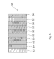
- Fig. 5 is a diagram showing the S and P-polarized light stitched together side-by-side on the polarization converter plate.
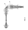
- Fig. 6 is an alternative embodiment of the illumination system shown in Fig. 3.
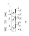
- Fig. 7 is a diagram of the polarization separator and translator of the system of Fig. 6.
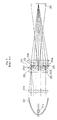
- a light source 30 having a reflector 32 is optically coupled to a light pipe 34.
- the light pipe is conventional in all respects except one.
- the light pipe 34 has a masked region at its input end, not seen in Fig. 3 but clearly illustrated in Fig. 4a.
- the light pipe 34 may be a light tunnel or other light reflecting structure having an input end that can be masked and an output end for outputting light.
- a polarization separator and translator 36 is disposed to receive substantially collimated light from the light pipe via lenses 35a and 35b in the form of a plurality of real images.
- a similar element 74 is shown in detail in Fig. 2.
- the polarization separator translator is disposed after the first two relay elements 37a and 37b. This region is essentially collimated space where the light exiting the relay element 37b is collimated.
- the function of the polarization separator translator 36 is to separate the orthogonal linear polarization states and then shift or translate one laterally sideways with respect to the other.
- unpolarized light is incident upon a PBS 36a, for example a Moxtek ProfluxTM wire grid polarizer with S-polarization being reflected and Polarization being transmitted.
- the P-polarized light is then reflected off a mirror 36b at the back of the translator 36 through the PBS.
- the separation of the mirror 36b from the PBS of translator 36 causes the P-polarized light to be shifted sideways relative to the S-polarized light. This separation needs to be controlled precisely as will be shown later.
- the input end face of the light pipe has two masked opaque regions 42a and 42b and has a light transmissive window 42c, therebetween.
- the width of the windowed region 42c is d/2 and the width of the masked regions are each d/4.
- the purpose of the masked regions is to yield an array of illuminated or light regions 45a and non-illuminated or dark 45b regions on the image plane.
- the light pipe receives the real image shown in Fig. 4a, and as light bounces within the light pipe a plurality of smaller virtual images are constructed, each a smaller version of the real image shown in Fig. 4a, at a virtual image plane about the input end of the light pipe.
- the polarization separator and translator 36 alters the multiple real images in a predetermined manner, such that approximately half the light within illuminated regions 45a is directed to non-illuminated or dark regions 45b by way of spatial translation, so as to stitch together side-by-side S-polarized light and P-polarized light.
- the PC 38 at a plane which is conjugate to the input face 33b of the light pipe as formed by the intervening relay optics has its retarding striped regions 52 coincident with only the S or P polarized light but not both.
- the PC 38 is designed to transform the P-polarized light into S-polarized light.
- One way to perform this is to laminate strips of half wave retarder material such as plastic retarder film, quartz, mica or other birefringent materials to a transparent substrate such as glass in a pattern which matches the pattern of the of the bright regions of the P-polarized light.
- the retarder is designed to rotate or retard the polarization axis by 90 degrees.
- Light emerging from the PC 38 will then be S-polarized light.
- S-polarized light can be transformed into P polarized light in a similar manner if desired.
- Fig. 6 an alternative embodiment of the invention is shown, wherein the polarization separator and translator 36 and polarization converter 38 of Fig. 3 are replaced with an optional mirror 62 for folding light incident thereon, and for redirecting the light to a polarization separator, translator, and converter 64 shown in more detail in Fig 7.
- Unpolarized light having S and P linear polarization components is incident upon an array of elements as shown.
- the absence of light between the arrows indicating beams of S and P-polarized light is due to the dark regions as a function of the input of the light pipe 32 or reflector being masked.
- the light shown by way of example, as three arrows, representing three beams is incident upon polarization beam splitters 75a, 75b, and 75c.
- This embodiment of the invention also takes advantage of the plural real images which represent the masked input to provide illuminated and non-illuminated regions. In this embodiment individual beams are split and stitched, one beside the other, to fill in the dark regions; this also provides an opportunity to rotate the S-polarized light while not affecting the P-polarized light after filling in the dark regions.
- the light pipe or reflector has an obstruction preventing light from entering.
- These dark regions can subsequently be filled in with about 50% of the light present in the light regions, in a polarization dependent manner, such that the remaining light is of one linear polarization and the translated shifted light is of an orthogonal polarization.
- One of the two linear polarizations can conveniently be retarded or rotated to be the same as the other, thereby providing a substantially uniform beam having a same polarization state.
Landscapes
- Physics & Mathematics (AREA)
- General Physics & Mathematics (AREA)
- Engineering & Computer Science (AREA)
- Multimedia (AREA)
- Signal Processing (AREA)
- Optics & Photonics (AREA)
- Projection Apparatus (AREA)
- Liquid Crystal (AREA)
Applications Claiming Priority (4)
| Application Number | Priority Date | Filing Date | Title |
|---|---|---|---|
| US56237004P | 2004-04-15 | 2004-04-15 | |
| US562370P | 2004-04-15 | ||
| US56974604P | 2004-05-10 | 2004-05-10 | |
| US569746P | 2004-05-10 |
Publications (2)
| Publication Number | Publication Date |
|---|---|
| EP1596228A1 true EP1596228A1 (fr) | 2005-11-16 |
| EP1596228B1 EP1596228B1 (fr) | 2007-07-25 |
Family
ID=34935253
Family Applications (1)
| Application Number | Title | Priority Date | Filing Date |
|---|---|---|---|
| EP05008321A Expired - Lifetime EP1596228B1 (fr) | 2004-04-15 | 2005-04-15 | Système d'éclairage avec conversion de polarisation optique |
Country Status (5)
| Country | Link |
|---|---|
| US (1) | US7387388B2 (fr) |
| EP (1) | EP1596228B1 (fr) |
| JP (1) | JP2005301281A (fr) |
| CN (1) | CN1683992A (fr) |
| DE (1) | DE602005001720T2 (fr) |
Families Citing this family (14)
| Publication number | Priority date | Publication date | Assignee | Title |
|---|---|---|---|---|
| JP4100276B2 (ja) * | 2003-07-04 | 2008-06-11 | セイコーエプソン株式会社 | 照明装置及びプロジェクタ |
| FR2872588A1 (fr) * | 2004-07-02 | 2006-01-06 | Thomson Licensing Sa | Systeme d'illumination pour imageur et projecteur correspondant |
| EP1873573A1 (fr) * | 2006-06-28 | 2008-01-02 | JDS Uniphase Corporation | Plaque de récupération de polarisation |
| DE202007019714U1 (de) | 2006-09-29 | 2016-08-30 | Reald Inc. | Polarisationsumwandlungssystem für stereoskopische Projektionen |
| MX2009012113A (es) | 2007-05-09 | 2010-03-15 | Real D | Sistema de conversion de polarizacion y método para proyección estereoscópica. |
| JP4329852B2 (ja) * | 2007-07-11 | 2009-09-09 | セイコーエプソン株式会社 | 偏光変換ユニット、偏光変換装置、およびプロジェクタ |
| US9074852B2 (en) * | 2007-11-12 | 2015-07-07 | The Boeing Company | Surveillance image denial verification |
| JP5930600B2 (ja) * | 2011-04-08 | 2016-06-08 | キヤノン株式会社 | 偏光分離素子および画像投射装置 |
| TWI442097B (zh) | 2012-02-22 | 2014-06-21 | 台達電子工業股份有限公司 | 用於一投影裝置之極化轉換元件組及投影裝置 |
| JP6290523B2 (ja) * | 2012-03-02 | 2018-03-07 | セイコーエプソン株式会社 | プロジェクター |
| TWI446094B (zh) | 2012-04-17 | 2014-07-21 | Delta Electronics Inc | 用於一投影裝置之光源系統及投影裝置 |
| US9625745B2 (en) | 2013-11-15 | 2017-04-18 | Reald Inc. | High dynamic range, high contrast projection systems |
| KR20240038823A (ko) | 2016-12-01 | 2024-03-25 | 매직 립, 인코포레이티드 | 스캐닝 어레이 광 엔진을 갖는 프로젝터 |
| CN110618480B (zh) * | 2019-09-26 | 2021-04-13 | 上海科乃特激光科技有限公司 | 一种90°偏转的光学元件、其使用方法及应用 |
Citations (4)
| Publication number | Priority date | Publication date | Assignee | Title |
|---|---|---|---|---|
| US4045133A (en) * | 1975-06-13 | 1977-08-30 | Rca Corporation | Analog optical block processor |
| US6139157A (en) * | 1997-02-19 | 2000-10-31 | Canon Kabushiki Kaisha | Illuminating apparatus and projecting apparatus |
| WO2001081960A1 (fr) * | 2000-04-25 | 2001-11-01 | Honeywell International Inc. | Guide optique a cavite creuse destine a la distribution de lumiere collimee a destination d'un afficheur a cristaux liquides |
| WO2002063390A2 (fr) * | 2001-02-05 | 2002-08-15 | Wavien, Inc. | Moteur d'eclairage pour affichage de projection utilisant un conducteur de lumiere conique |
Family Cites Families (4)
| Publication number | Priority date | Publication date | Assignee | Title |
|---|---|---|---|---|
| US6343862B1 (en) * | 1998-11-20 | 2002-02-05 | Minolta Co., Ltd. | Projecting image display device |
| US6839095B2 (en) * | 2002-05-17 | 2005-01-04 | Infocus Corporation | Single-path color video projection systems employing reflective liquid crystal display devices |
| JP4120414B2 (ja) * | 2003-02-07 | 2008-07-16 | 三菱電機株式会社 | 投写型表示装置及び画像信号の変換方法 |
| KR20050025538A (ko) * | 2003-09-08 | 2005-03-14 | 삼성전자주식회사 | 조명장치 |
-
2005
- 2005-04-11 US US11/103,154 patent/US7387388B2/en not_active Expired - Fee Related
- 2005-04-12 JP JP2005114358A patent/JP2005301281A/ja active Pending
- 2005-04-15 CN CNA2005100645727A patent/CN1683992A/zh active Pending
- 2005-04-15 DE DE602005001720T patent/DE602005001720T2/de not_active Expired - Lifetime
- 2005-04-15 EP EP05008321A patent/EP1596228B1/fr not_active Expired - Lifetime
Patent Citations (4)
| Publication number | Priority date | Publication date | Assignee | Title |
|---|---|---|---|---|
| US4045133A (en) * | 1975-06-13 | 1977-08-30 | Rca Corporation | Analog optical block processor |
| US6139157A (en) * | 1997-02-19 | 2000-10-31 | Canon Kabushiki Kaisha | Illuminating apparatus and projecting apparatus |
| WO2001081960A1 (fr) * | 2000-04-25 | 2001-11-01 | Honeywell International Inc. | Guide optique a cavite creuse destine a la distribution de lumiere collimee a destination d'un afficheur a cristaux liquides |
| WO2002063390A2 (fr) * | 2001-02-05 | 2002-08-15 | Wavien, Inc. | Moteur d'eclairage pour affichage de projection utilisant un conducteur de lumiere conique |
Also Published As
| Publication number | Publication date |
|---|---|
| US20050231690A1 (en) | 2005-10-20 |
| EP1596228B1 (fr) | 2007-07-25 |
| JP2005301281A (ja) | 2005-10-27 |
| US7387388B2 (en) | 2008-06-17 |
| DE602005001720D1 (de) | 2007-09-06 |
| DE602005001720T2 (de) | 2008-04-30 |
| CN1683992A (zh) | 2005-10-19 |
Similar Documents
| Publication | Publication Date | Title |
|---|---|---|
| JP3697013B2 (ja) | 照明装置及びそれを用いた投影装置 | |
| JP5164421B2 (ja) | 色分解合成光学系およびそれを用いた画像投影装置 | |
| JP5263031B2 (ja) | 投写型表示装置 | |
| JP2004527803A (ja) | 画像表示装置 | |
| EP1596228B1 (fr) | Système d'éclairage avec conversion de polarisation optique | |
| KR20140081885A (ko) | 경사진 이색성 편광 빔 스플리터 | |
| RU96120149A (ru) | Оптическая проекционная система | |
| US6331879B1 (en) | Liquid crystal projector with an illumination optical system | |
| EP1191796B1 (fr) | Dispositif optique et dispositif d' affichage du type à projection | |
| JP3269362B2 (ja) | 液晶プロジェクター | |
| JPH07244282A (ja) | 照明装置及びそれを用いた投影装置 | |
| JP2000056266A (ja) | 光学装置 | |
| JP2007102101A (ja) | 照明光学系及びそれを有する画像投射装置 | |
| JP3658404B2 (ja) | 投影装置 | |
| CN100385335C (zh) | 图像投影系统或者可视化系统 | |
| CN100460930C (zh) | Lcos光学投影系统 | |
| KR0184364B1 (ko) | 반사형 광모듈레이터를 이용한 투사형 입체화상표시장치 | |
| US6705731B2 (en) | Projection type display apparatus | |
| JPH09318907A (ja) | 投写型表示装置 | |
| JPH10319349A (ja) | 偏光変換素子及びそれを用いた投影装置 | |
| JP3327908B2 (ja) | 表示装置及びそれを用いた投射装置 | |
| JP3496014B2 (ja) | 液晶投射装置 | |
| US20080024728A1 (en) | Imager Illumination System and Corresponding Projector | |
| JP3550261B2 (ja) | 液晶プロジェクタ | |
| JPH07294922A (ja) | 表示装置及びそれを用いた投射装置 |
Legal Events
| Date | Code | Title | Description |
|---|---|---|---|
| PUAI | Public reference made under article 153(3) epc to a published international application that has entered the european phase |
Free format text: ORIGINAL CODE: 0009012 |
|
| AK | Designated contracting states |
Kind code of ref document: A1 Designated state(s): AT BE BG CH CY CZ DE DK EE ES FI FR GB GR HU IE IS IT LI LT LU MC NL PL PT RO SE SI SK TR |
|
| AX | Request for extension of the european patent |
Extension state: AL BA HR LV MK YU |
|
| 17P | Request for examination filed |
Effective date: 20060511 |
|
| AKX | Designation fees paid |
Designated state(s): DE GB |
|
| 17Q | First examination report despatched |
Effective date: 20060728 |
|
| GRAP | Despatch of communication of intention to grant a patent |
Free format text: ORIGINAL CODE: EPIDOSNIGR1 |
|
| GRAS | Grant fee paid |
Free format text: ORIGINAL CODE: EPIDOSNIGR3 |
|
| GRAA | (expected) grant |
Free format text: ORIGINAL CODE: 0009210 |
|
| AK | Designated contracting states |
Kind code of ref document: B1 Designated state(s): DE GB |
|
| REG | Reference to a national code |
Ref country code: GB Ref legal event code: FG4D |
|
| REF | Corresponds to: |
Ref document number: 602005001720 Country of ref document: DE Date of ref document: 20070906 Kind code of ref document: P |
|
| PLBE | No opposition filed within time limit |
Free format text: ORIGINAL CODE: 0009261 |
|
| STAA | Information on the status of an ep patent application or granted ep patent |
Free format text: STATUS: NO OPPOSITION FILED WITHIN TIME LIMIT |
|
| 26N | No opposition filed |
Effective date: 20080428 |
|
| PGFP | Annual fee paid to national office [announced via postgrant information from national office to epo] |
Ref country code: DE Payment date: 20100428 Year of fee payment: 6 |
|
| PGFP | Annual fee paid to national office [announced via postgrant information from national office to epo] |
Ref country code: GB Payment date: 20100426 Year of fee payment: 6 |
|
| GBPC | Gb: european patent ceased through non-payment of renewal fee |
Effective date: 20110415 |
|
| PG25 | Lapsed in a contracting state [announced via postgrant information from national office to epo] |
Ref country code: DE Free format text: LAPSE BECAUSE OF NON-PAYMENT OF DUE FEES Effective date: 20111101 |
|
| PG25 | Lapsed in a contracting state [announced via postgrant information from national office to epo] |
Ref country code: GB Free format text: LAPSE BECAUSE OF NON-PAYMENT OF DUE FEES Effective date: 20110415 |
|
| REG | Reference to a national code |
Ref country code: DE Ref legal event code: R119 Ref document number: 602005001720 Country of ref document: DE Effective date: 20111101 |