EP1596252A1 - Lithographischer Apparat und Verfahren zur Herstellung einer Vorrichtung - Google Patents
Lithographischer Apparat und Verfahren zur Herstellung einer Vorrichtung Download PDFInfo
- Publication number
- EP1596252A1 EP1596252A1 EP05103924A EP05103924A EP1596252A1 EP 1596252 A1 EP1596252 A1 EP 1596252A1 EP 05103924 A EP05103924 A EP 05103924A EP 05103924 A EP05103924 A EP 05103924A EP 1596252 A1 EP1596252 A1 EP 1596252A1
- Authority
- EP
- European Patent Office
- Prior art keywords
- radiation
- gas
- lithographic apparatus
- transmissive
- euv
- Prior art date
- Legal status (The legal status is an assumption and is not a legal conclusion. Google has not performed a legal analysis and makes no representation as to the accuracy of the status listed.)
- Granted
Links
Images

Classifications
-
- G—PHYSICS
- G03—PHOTOGRAPHY; CINEMATOGRAPHY; ANALOGOUS TECHNIQUES USING WAVES OTHER THAN OPTICAL WAVES; ELECTROGRAPHY; HOLOGRAPHY
- G03F—PHOTOMECHANICAL PRODUCTION OF TEXTURED OR PATTERNED SURFACES, e.g. FOR PRINTING, FOR PROCESSING OF SEMICONDUCTOR DEVICES; MATERIALS THEREFOR; ORIGINALS THEREFOR; APPARATUS SPECIALLY ADAPTED THEREFOR
- G03F7/00—Photomechanical, e.g. photolithographic, production of textured or patterned surfaces, e.g. printing surfaces; Materials therefor, e.g. comprising photoresists; Apparatus specially adapted therefor
- G03F7/70—Microphotolithographic exposure; Apparatus therefor
- G03F7/70058—Mask illumination systems
- G03F7/70191—Optical correction elements, filters or phase plates for controlling intensity, wavelength, polarisation, phase or the like
-
- G—PHYSICS
- G03—PHOTOGRAPHY; CINEMATOGRAPHY; ANALOGOUS TECHNIQUES USING WAVES OTHER THAN OPTICAL WAVES; ELECTROGRAPHY; HOLOGRAPHY
- G03F—PHOTOMECHANICAL PRODUCTION OF TEXTURED OR PATTERNED SURFACES, e.g. FOR PRINTING, FOR PROCESSING OF SEMICONDUCTOR DEVICES; MATERIALS THEREFOR; ORIGINALS THEREFOR; APPARATUS SPECIALLY ADAPTED THEREFOR
- G03F7/00—Photomechanical, e.g. photolithographic, production of textured or patterned surfaces, e.g. printing surfaces; Materials therefor, e.g. comprising photoresists; Apparatus specially adapted therefor
- G03F7/70—Microphotolithographic exposure; Apparatus therefor
- G03F7/70008—Production of exposure light, i.e. light sources
- G03F7/70033—Production of exposure light, i.e. light sources by plasma extreme ultraviolet [EUV] sources
-
- G—PHYSICS
- G03—PHOTOGRAPHY; CINEMATOGRAPHY; ANALOGOUS TECHNIQUES USING WAVES OTHER THAN OPTICAL WAVES; ELECTROGRAPHY; HOLOGRAPHY
- G03F—PHOTOMECHANICAL PRODUCTION OF TEXTURED OR PATTERNED SURFACES, e.g. FOR PRINTING, FOR PROCESSING OF SEMICONDUCTOR DEVICES; MATERIALS THEREFOR; ORIGINALS THEREFOR; APPARATUS SPECIALLY ADAPTED THEREFOR
- G03F7/00—Photomechanical, e.g. photolithographic, production of textured or patterned surfaces, e.g. printing surfaces; Materials therefor, e.g. comprising photoresists; Apparatus specially adapted therefor
- G03F7/70—Microphotolithographic exposure; Apparatus therefor
- G03F7/70483—Information management; Active and passive control; Testing; Wafer monitoring, e.g. pattern monitoring
- G03F7/7055—Exposure light control in all parts of the microlithographic apparatus, e.g. pulse length control or light interruption
- G03F7/70575—Wavelength control, e.g. control of bandwidth, multiple wavelength, selection of wavelength or matching of optical components to wavelength
Definitions
- This invention relates to a lithographic apparatus, a method for diminishing an intensity of undesired radiation in a beam of radiation in an optical system, for example in a lithographic apparatus, a device manufacturing method, the use of a gas in an optical system, and a device.
- a lithographic apparatus is a machine that applies a desired pattern onto a target portion of a substrate.
- Lithographic apparatus can be used, for example, in the manufacture of integrated circuits (ICs).
- a patterning structure such as a mask, may be used to generate a circuit pattern corresponding to an individual layer of the IC, and this pattern can be imaged onto a target portion (e.g. comprising part of, one or several dies) on a substrate (e.g. a silicon wafer) that has a layer of radiation-sensitive material (resist).
- a single substrate will contain a network of adjacent target portions that are successively exposed.
- lithographic apparatuses include so-called steppers, in which each target portion is irradiated by exposing an entire pattern onto the target portion in one go, and so-called scanners, in which each target portion is irradiated by scanning the pattern through the projection beam in a given direction (the "scanning"-direction) while synchronously scanning the substrate parallel or anti-parallel to this direction.
- lithographic projection apparatus In a lithographic apparatus the size of features that can be imaged onto the substrate is limited by the wavelength of the projection radiation. To produce integrated circuits with a higher density of devices, and hence higher operating speeds, it is desirable to be able to image smaller features. While most current lithographic projection apparatuses employ ultraviolet light generated by mercury lamps or excimer lasers, it has been proposed to use shorter wavelength radiation, e.g. of around 13 nm. Such radiation is termed extreme ultraviolet (EUV) or soft x-ray, and possible sources include, for instance, laser-produced plasma sources, discharge plasma sources, or synchrotron radiation from electron storage rings.
- EUV extreme ultraviolet
- soft x-ray Such radiation is termed extreme ultraviolet (EUV) or soft x-ray
- possible sources include, for instance, laser-produced plasma sources, discharge plasma sources, or synchrotron radiation from electron storage rings.
- Some extreme ultraviolet sources emit radiation over a wide range of frequencies, even including infrared (IR), visible, ultraviolet (UV) and deep ultraviolet (DUV). These unwanted frequencies will propagate and cause heating problems in the illumination and projection systems and cause unwanted exposure of the resist if not blocked; although the multilayer mirrors of the illumination and projection systems are optimized for reflection of the desired wavelength, e.g. 13 nm, they are optically flat and have quite high reflectivities at IR, visible and UV wavelengths. It is therefore desirable to select from the source a relatively narrow band of frequencies for the projection beam. Even where the source has a relatively narrow emission line, it is desirable to reject radiation out of that line, especially at longer wavelengths. It has been proposed to use a thin membrane as a filter to perform this function.
- a membrane filter also generally absorbs at least 50% of the desired radiation.
- EP 1197803 describes a lithographic projection apparatus wherein a grating spectral filter is used in the radiation system of the lithographic projection apparatus.
- This grating spectral filter is designed for passing radiation of desired wavelengths to form a projection beam and for deflecting radiation of undesired wavelengths.
- the grating spectral filter is substantially formed of a material having a complex refractive index close to unity at the desired wavelengths and includes silicon protrusions (this structure is 'invisible' for the EUV radiation).
- the protrusions have a laminar saw tooth profile or a laminar square wave profile (figures 3 and 4 of EP 1197803, respectively).
- the grating spectral filter of EP 1197803 may lead to a large loss in reflectivity, also of the desired radiation.
- loss of radiation intensity can amount up to 50% or more.
- optical filter in an optical system, e.g. a lithographic apparatus, wherein the optical filter may e.g. induce less intensity loss of desired radiation. It is further an aspect of the invention to provide a method for diminishing an intensity of undesired radiation in a beam of radiation in an optical system, as well as a device manufacturing method, wherein optical filters are used that may, e.g., induce less intensity loss of desired radiation.
- a lithographic apparatus including:
- a lithographic apparatus including:
- UV radiation e.g. having a wavelength ⁇ of about 365, 248, 193, 157 or 126 nm
- EUV radiation e.g. having a wavelength in the range of about 5-20 nm
- particle beams such as ion beams or electron beams.
- radiation having wavelengths between about 780-3000 nm (or larger) is considered IR radiation.
- UV refers to radiation with wavelengths of approximately 100-400 nm; within lithography, it is usually also applied to the wavelengths which can be produced by a mercury discharge lamp: G-line 436 nm; H-line 405 nm; I-line 365 nm.
- VUV is Vacuum UV (i.e. UV absorbed by air) and refers to wavelengths of approximately 100-200 nm.
- DUV is Deep UV, and is usually used in lithography for the wavelengths produced by excimer lasers like 126 nm - 248 nm.
- Undesired radiation or “undesired wavelength” refers to radiation having wavelengths larger (or smaller) than the wavelength that is intended to be used. For example, when EUV radiation with a wavelength ⁇ of about 13.5 nm is desired, radiation with a wavelength smaller than about 10 nm or larger than about 20 nm is undesired; more preferably radiation not having wavelengths in the range of about 13.5 nm +/- 2%, is undesired radiation. This means that the phrase "radiation with wavelength ⁇ " is not intended to be limited to radiation with an infinite small bandwidth of ⁇ , as will be clear to the person skilled in the art.
- An optical element may be designed, and a gas may be used, for one specific wavelength ⁇ or a range of wavelengths.
- in-band EUV refers to EUV radiation having a wavelength in the range of about 10-16 nm, especially about 13.5 nm +/- 2%; out-band EUV is radiation having a wavelength smaller or larger than this wavelength range for in-band EUV, e.g. x-rays, VUV, DUV, visible and IR.
- One advantage of the lithographic apparatus of the invention is that, when e.g. applying EUV radiation, one or more selected from out-band EUV radiation, VUV radiation and DUV radiation may be diminished relatively more than the desired EUV radiation (EUV in-band radiation).
- EUV in-band radiation EUV in-band radiation
- a gaseous optical filter function is provided, that may filter out at least part of the undesired radiation, while leading to a smaller or no loss in intensity of at least part of the desired (e.g. EUV) radiation than is for example the case with state of the art optical filters (like those of EP 1197803).
- the invention is directed to a lithographic apparatus, wherein the desired radiation includes EUV radiation, wherein the beam of radiation includes EUV radiation and wherein the transmissive gas includes an EUV transmissive gas.
- the desired radiation includes in-band EUV radiation; undesired radiation is all radiation (out-band) having wavelengths other than 10-16 nm.
- this gas substantially transmissive for at least part of the desired radiation and substantially less transmissive for at least part of the undesired radiation is a gas that substantially absorbs undesired radiation.
- the invention is directed to a lithographic apparatus, wherein at least a part of the lithographic apparatus includes at least about 0.1 Pa.m of EUV transmissive gas.
- a lithographic apparatus wherein at least a part of the lithographic apparatus includes at least about 1 Pa.m of EUV transmissive gas, Pa.m being the pressure integrated over a length of the beam of radiation traversing the part of the apparatus comprising the EUV transmissive gas, wherein the length is in meters [m] and the pressure is in Pascal [Pa].
- 1 Pam equals 0.01 mbarm, wherein the pressure is given in "mbar", and the length in "m”.
- 10 Pa.m (0.1 mbar.m) of He can be achieved when a beam of radiation traverses 1 meter through a volume with a pressure of 10 Pa (0.1 mbar) He, or for example, when the optical path length is 0.5 m through a volume with 20 Pa (0.2 mbar) of He.
- Absorption, especially of undesired radiation becomes significant from about 0.1 Pa.m for argon and nitrogen; for helium this number is from about 1 Pa.m. This attenuation appears to depend on the gas atoms absorbing and is small for light gasses (e.g. helium) en higher for heavier gases (e.g. argon, nitrogen).
- the invention is directed to a lithographic apparatus, wherein the lithographic apparatus includes EUV transmissive gas in the range of about 0.1-100 Pa.m.
- the lithographic apparatus includes EUV transmissive gas in the range of about 1-100 Pa.m.
- the invention is directed to a lithographic apparatus, wherein the undesired radiation includes radiation selected from at least one of out-band EUV radiation, VUV radiation and DUV radiation.
- the invention is directed to a lithographic apparatus, wherein the EUV transmissive gas includes a gas selected from at least one of He, Ne, Ar, Kr, Xe, N 2 , CO, CO 2 and O 2 . These gasses provide the desired optical filter function, but are also inert.
- the invention is directed to a lithographic apparatus, wherein at least a part of the lithographic apparatus includes at least about 0.1 Pa.m of Ar, e.g. between about 0.1-10 Pa.m Ar, like e.g. about 1-10 Pa.m of Ar.
- the invention is directed to a lithographic apparatus, wherein at least a part of the lithographic apparatus includes at least about 1 Pa.m of He, e.g. between about 1-100 Pa.m of He, like e.g. about 10-100 Pa.m, and in yet a next embodiment, the invention is directed to a lithographic apparatus, wherein at least a part of the lithographic apparatus includes at least about 0.1 Pa.m of N 2 , e.g. between about 0.1-10 Pa.m of N 2 , like e.g. about 1-10 Pa.m of N 2 .
- the gaseous optical filter can be used in different optical apparatus, and in different parts of such optical apparatus.
- the invention is directed to a lithographic apparatus, wherein at least a part of the lithographic apparatus includes the EUV transmissive gas, wherein the lithographic apparatus includes a collection chamber, and wherein the part of the lithographic apparatus including the EUV transmissive gas is selected from at least one of the collection chamber, the illumination system and the projection system.
- the EUV transmissive gas is included in the collection chamber.
- advantageously undesired radiation is at least partly filtered out at an early stage, leading to less potential damage of other (non-gaseous) optical filters or optical elements and leading to better imaging properties.
- the part of the lithographic apparatus including an EUV transmissive gas includes the collection chamber, the illumination system and the projection system.
- the invention is directed to a lithographic apparatus, wherein the at least one of the collection chamber, illumination system and projection system has a gas pressure of the EUV transmissive gas of at least about 0.01 Pa of EUV transmissive gas, e.g. about 0.01-10 Pa of EUV transmissive gas, like e.g. about 0.01-10 Pa or about 0.1-100 Pa, e.g. about 0.1-10 Pa, depending e.g. on the kind of EUV transmissive gas or combination of EUV transmissive gasses.
- a gas pressure of the EUV transmissive gas of at least about 0.01 Pa of EUV transmissive gas, e.g. about 0.01-10 Pa of EUV transmissive gas, like e.g. about 0.01-10 Pa or about 0.1-100 Pa, e.g. about 0.1-10 Pa, depending e.g. on the kind of EUV transmissive gas or combination of EUV transmissive gasses.
- the invention is directed to a lithographic apparatus, wherein at least a part of the lithographic apparatus includes the EUV transmissive gas, wherein the lithographic apparatus includes a collection chamber, and wherein the part of the lithographic apparatus including the EUV transmissive gas is a dynamic gas lock selected from at least one of a first dynamic gas lock between the collection chamber and the illumination system, a second dynamic gas lock between the illumination system and projection system, and a third dynamic gas lock between the projection system and the substrate table.
- this can be a gas lock based on the gas locks described in e.g. US6459472, which is incorporated herein by reference.
- the invention is directed to a lithographic apparatus, wherein the dynamic gas lock includes at least 1 Pa.m of EUV transmissive gas, e.g. at least 2 Pa.m, like 1-100 Pa.m, e.g. 2-100 Pa.m.
- a method for diminishing an intensity of undesired radiation in a beam of radiation in an optical system including a source for providing radiation, the radiation including desired radiation having a predetermined wavelength or a predetermined wavelength range, and undesired radiation having another wavelength or wavelength range, characterized by providing in the beam of radiation a gas substantially transmissive for at least part of the desired radiation and substantially less transmissive for at least part of the undesired radiation.
- a method for diminishing an intensity of undesired radiation in a beam of radiation in an optical system comprising a source configured to provide radiation, the radiation comprising desired radiation having a predetermined wavelength or a predetermined wavelength range, and undesired radiation having another wavelength or another wavelength range, the method including introducing into the beam of radiation a gas substantially transmissive for at least part of the desired radiation and substantially less transmissive for at least part of the undesired radiation.
- the advantage of such a method for diminishing an intensity of undesired radiation in a beam of radiation in an optical system according to the invention is that, when e.g. applying EUV radiation, one or more selected from out-band EUV radiation, VUV radiation and DUV radiation may be diminished relatively more than the desired EUV radiation (EUV in-band radiation).
- EUV in-band radiation EUV in-band radiation
- a gaseous optical filter function is provided, that may filter out at least part of the undesired radiation, while leading to a smaller or no loss in intensity of at least part of the desired (e.g. EUV) radiation than is for example the case with state of the art optical filters (like those of EP 1197803).
- the invention is directed to a method, wherein the desired radiation includes EUV radiation, wherein the beam of radiation includes EUV radiation and wherein the transmissive gas includes an EUV transmissive gas.
- the invention is directed to a method wherein the undesired radiation includes radiation selected from at least one of out-band EUV radiation, VUV radiation and DUV radiation.
- the invention is directed to a method wherein at least part of the optical system includes the EUV transmissive gas, the method further including providing in the beam of radiation at least about 0.1 Pa.m of EUV transmissive gas, Pa.m being the pressure integrated over a length of the beam of radiation traversing the part of the optical system comprising the EUV transmissive gas.
- the method for diminishing an intensity of undesired radiation in a beam of radiation in an optical system is, in analogy to the herein mentioned embodiments of the lithographic apparatus of the invention, also directed to e.g. an embodiment, wherein at least a part of the optical system includes at least about 0.1 Pa.m of Ar; an embodiment, wherein at least a part of the optical system includes at least about 1 Pa.m of He; an embodiment, wherein at least a part of the optical system includes at least about 0.1 Pa.m of N 2 .
- the optical system that is used in this method may e.g. be a lithographic apparatus, e.g. the lithographic apparatus of the invention as described herein.
- the invention is also directed to a device manufacturing method including
- a device manufacturing method including:
- the invention is also directed to e.g. an embodiment of the device manufacturing method, wherein the desired radiation includes EUV radiation, wherein the beam of radiation includes EUV radiation and wherein the transmissive gas includes an EUV transmissive gas; or to an embodiment, wherein the undesired radiation includes radiation selected from at least one of out-band EUV radiation, VUV radiation and DUV radiation.
- the invention is directed to a method, wherein a lithographic apparatus is used, wherein at least part of the lithographic apparatus includes the EUV transmissive gas and wherein the method further includes providing in the beam of radiation at least about 0.1 Pa.m of EUV transmissive gas, Pa.m being the pressure integrated over a length of the beam of radiation traversing the part of the apparatus including the EUV transmissive gas.
- the invention is also directed to e.g.
- the optical system that is used in this method may e.g. be the lithographic apparatus of the invention.
- the lithographic apparatus used in this device manufacturing method may include a collection chamber, an illumination system and a projection system, etc.
- a dynamic gas lock including:
- the invention is directed to the use of a gas as optical filter in a beam of radiation of an optical system, the optical system including a source for providing radiation, the radiation including desired radiation having a predetermined wavelength or a predetermined wavelength range, and undesired radiation having another wavelength or wavelength range, and wherein the gas used as optical filter is a gas substantially transmissive for at least part of the desired radiation and substantially less transmissive for at least part of the undesired radiation.
- the invention is directed to a method, wherein the desired radiation includes EUV radiation, wherein the beam of radiation includes EUV radiation and wherein the transmissive gas includes an EUV transmissive gas.
- the gas can be used to stop, trap or diminish debris, e.g. from an EUV source, traveling along the beam of radiation, from reaching the substrate, or from reaching other optical elements (like gratings, mirrors, lenses).
- the transmissive gas can be used as both optical filter and as a structure for at least one of stopping and trapping of debris from the beam of radiation and reducing sputtering due to the debris.
- the gas may also advantageously be used to stop, trap or diminish debris sputtering from the substrate when being irradiated with the beam of radiation.
- a device which is manufactured according to the device manufacturing method of the invention or with the lithographic apparatus according to the invention.
- Transmissive or “substantially transmissive” in this context means that the transmission through a gas (transmissive for at least part of the desired radiation), e.g. an EUV transmissive gas, is larger than zero, preferably e.g. at least about 30%, or at least about 50%, at least about 70%, at least about 80%, e.g. at least about 90% or at least about 95%, more preferably at least about 98%. Consequently, "absorbed” means that the absorption is larger than zero, preferably e.g. at least about 30%, or at least about 50%, at least about 70%, at least about 80%, e.g. at least about 90% or at least about 95%, more preferably at least about 98%.
- EUV transmissive or “transmissive for EUV radiation” mean that the gas is transmissive for at least part of the EUV radiation (especially in-band EUV). This can e.g. be a gas substantially transmissive for radiation with a predefined in-band wavelength in the range of about 12-14 nm.
- the phrases "less transmissive” or “substantially less transmissive” in the context of the invention mean that the gas has a smaller transmission for a wavelength, a wavelength range or wavelength ranges with respect to the transmission of radiation with undesired wavelengths.
- Each gas, having a transmission for at least part of the desired radiation (like e.g. in-band EUV radiation) which is larger than for at least part of the undesired radiation can be used as optical filter.
- those gasses are chosen that have a substantial larger transmission for at least part of the desired radiation than for at least part of the undesired radiation, e.g. a transmission difference of e.g. about 30%, like e.g. about 50%.
- such difference only refers to certain wavelengths, like e.g. a transmission difference of about 30% between the transmission at 13.5 nm and 35 nm, which is e.g. the case when a pressure of about 0.01 mbar.m (1 Pam) of N 2 is present (Pa.m being the pressure integrated over a length of the beam of radiation traversing the part of the apparatus comprising the EUV transmissive gas), see also figure 3.
- the term "at least part of the radiation” refers to at least part of a spectral wavelength range.
- a gas can be substantially transmissive or substantially less transmissive or substantially absorb radiation in one or more different wavelength ranges.
- the transmission of the gasses depends amongst others on the pressure of the gas and the path length that the beam of radiation traverses. Values of pressures in Pa or Pa.m may be given in values like "at least 0.1 Pa.m” or at least 0.01 Pa". A pressure can be chosen such that the desired filter function is obtained and enough radiation intensity of desired radiation of the beam of radiation is obtained.
- not absorbed or “substantially not absorbed” in this context means that the absorption of radiation is less than about 100%, preferably less than e.g. about 70%, or less than about 50%, or less than about 30%, less than about 20%, e.g. less than about 10% or less than about 5%, more preferably less than about 2%. It should be appreciated that, “transmissive”, “absorbed” as well as “not absorbed” depend not only on the transmission or absorbance of the gas, but also on other factors like e.g. path length of the beam of radiation traversing through the gas.
- transmissive refers to a wavelength, a wavelength range or wavelength ranges.
- a gas less transmissive for VUV radiation which may be applied according to the invention, can however be transmissive for parts of UV or DUV radiation.
- transmissive have to be understood as related to at least part of the desired radiation or at least part of the undesired radiation.
- the gasses in the context of the invention are those gasses that can be used as optical filter to improve the ratio of desired radiation, or at least part of the desired radiation, over the undesired radiation, or at least part of the undesired radiation.
- a gas for EUV applications, with EUV wavelengths of 5-20 nm, such a gas includes a gas selected from at least one of He, Ne, Ar, Kr, Xe, N2, CO, CO2 and 02. This includes also combination of gasses.
- values related to pressure like those expressed in Pa (mbar) or in Pa.m (mbar.m) are either related to a gas or related to a combination of gasses, wherein the gasses are gasses according to the invention.
- gasses can be used when they are also able to fulfill a filter function.
- the gasses are inert.
- absorbencies and differences in absorbencies of the gasses have to be taken into account.
- optical system may e.g. include a lithographic apparatus.
- An optical system may include different components, for example a collection chamber, an illumination system and a projection system, but also a first dynamic gas lock between the collection chamber and the illumination system, a second dynamic gas lock between the illumination system and projection system, and a third dynamic gas lock between the projection system and the substrate table.
- Each component has a certain volume, filled with a gas, a combination of gasses, or is substantially vacuum.
- the optical system when including different components, each having a certain volume, may also include intermediate spaces or volumes, traversed by the beam of radiation.
- optical system or lithographic apparatus may include one or more compartments or intermediate spaces (both may be indicated with volumes) which may include the gas substantially transmissive for at least part of the desired radiation and substantially less transmissive for at least part of the undesired radiation. In case more than one of such compartment and intermediate space is present, one or more of them may include this gas.
- the compartment, the compartments, the intermediate space or the intermediate spaces, respectively, are chosen to include this gas.
- the value of the pressure integrated over the optical path length is estimated by integrating the pressure over the optical path length (e.g. of the projection beam, especially the central ray of the projection beam) in each volume including the transmissive gas.
- any use of the terms "wafer” or “die” herein may be considered as synonymous with the more general terms “substrate” or “target portion”, respectively.
- the substrate referred to herein may be processed, before or after exposure, in for example a track (a tool that typically applies a layer of resist to a substrate and develops the exposed resist) or a metrology or inspection tool.
- the disclosure herein may be applied to such and other substrate processing tools.
- the substrate may be processed more than once, for example in order to create a multi-layer IC, so that the term substrate used herein may also refer to a substrate that already contains multiple processed layers.
- patterning structure used herein should be broadly interpreted as referring to a structure that can be used to impart a projection beam with a pattern in its cross-section such as to create a pattern in a target portion of the substrate. It should be noted that the pattern imparted to the projection beam might not exactly correspond to the desired pattern in the target portion of the substrate. Generally, the pattern imparted to the projection beam will correspond to a particular functional layer in a device being created in the target portion, such as an integrated circuit.
- Patterning structures may be transmissive or reflective.
- Examples of patterning structures include masks, programmable mirror arrays, and programmable LCD panels.
- Masks are well known in lithography, and include mask types such as binary, alternating phase-shift, and attenuated phase-shift, as well as various hybrid mask types.
- An example of a programmable mirror array employs a matrix arrangement of small mirrors, each of which can be individually tilted so as to reflect an incoming radiation beam in different directions; in this manner, the reflected beam is patterned.
- the support structure supports, i.e. bears the weight of, the patterning structure. It holds the patterning structure in a way depending on the orientation of the patterning structure, the design of the lithographic apparatus, and other conditions, such as for example whether or not the patterning structure is held in a vacuum environment.
- the support can be using mechanical clamping, vacuum, or other clamping techniques, for example electrostatic clamping under vacuum conditions.
- the support structure may be a frame or a table, for example, which may be fixed or movable as required and which may ensure that the patterning structure is at a desired position, for example with respect to the projection system. Any use of the terms "reticle” or “mask” herein may be considered synonymous with the more general term "patterning structure".
- projection system used herein should be broadly interpreted as encompassing various types of projection system, including refractive optical systems, reflective optical systems, and catadioptric optical systems, as appropriate for example for the exposure radiation being used, or for other factors such as the use of an immersion fluid or the use of a vacuum. Any use of the term “lens” herein may be considered as synonymous with the more general term “projection system”.
- the illumination system may also encompass various types of optical components, including refractive, reflective, and catadioptric optical components for directing, shaping, or controlling the projection beam of radiation, and such components may also be referred to below, collectively or singularly, as a "lens”.
- the lithographic apparatus may be of a type having two (dual stage) or more substrate tables (and/or two or more mask tables). In such "multiple stage” machines the additional tables may be used in parallel, or preparatory steps may be carried out on one or more tables while one or more other tables are being used for exposure.
- the lithographic apparatus may also be of a type wherein the substrate is immersed in a liquid having a relatively high refractive index, e.g. water, so as to fill a space between the fmal element of the projection system and the substrate.
- Immersion liquids may also be applied to other spaces in the lithographic apparatus, for example, between the mask and the first element of the projection system. Immersion techniques are well known in the art for increasing the numerical aperture of projection systems.
- Figure 1 schematically depicts a lithographic apparatus according to an embodiment of the invention
- Figure 2 schematically depicts a side view of an EUV illumination system and projection optics of a lithographic projection apparatus according to Figure 1.
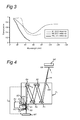
- Figure 3 schematically depicts the transmission of a number of gasses that can be applied according to the invention.
- Figure 4 schematically depicts a side view of another embodiment of the projection optics of a lithographic projection apparatus.
- FIG. 1 schematically depicts a lithographic apparatus according to an embodiment of the invention.
- the apparatus includes an illumination system (illuminator) IL configured to provide a projection beam PB of radiation (e.g. UV or EUV radiation), a first support structure (e.g. a mask table) MT configured to support patterning structure (e.g. a mask) MA and connected to first positioning device PM configured to accurately position the patterning device with respect to a projection system ("lens") PL; a substrate table (e.g. a wafer table) WT configured to hold a substrate (e.g. a resist-coated wafer) W and connected to second positioning device PW configured to accurately position the substrate with respect to the projection system PL; and a projection system (e.g. a reflective projection lens) PL configured to image a pattern imparted to the projection beam PB by patterning structure MA onto a target portion C (e.g. including one or more dies) of the substrate W.
- an illumination system illumination system
- the apparatus is of a reflective type (e.g. employing a reflective mask or a programmable mirror array of a type as referred to above).
- the apparatus may be of a transmissive type (e.g. employing a transmissive mask).
- the illuminator IL receives radiation from a radiation source SO.
- the source and the lithographic apparatus may be separate entities, for example when the source is a plasma discharge source. In such cases, the source is not considered to form part of the lithographic apparatus and the radiation is generally passed from the source SO to the illuminator IL with the aid of a radiation collector including for example suitable collecting mirrors and/or a spectral purity filter. In other cases the source may be integral part of the apparatus, for example when the source is a mercury lamp.
- the source SO and the illuminator IL may be referred to as a radiation system.
- the illuminator IL may include an adjusting device configured to adjust the angular intensity distribution of the beam. Generally, at least the outer and/or inner radial extent (commonly referred to as ⁇ -outer and ⁇ -inner, respectively) of the intensity distribution in a pupil plane of the illuminator can be adjusted.
- the illuminator provides a conditioned beam of radiation, PB having a desired uniformity and intensity distribution in its cross-section.
- the beam PB is incident on the mask MA, which is held on the mask table MT. Being reflected by the mask MA, the beam PB passes through the lens PL, which focuses the beam onto a target portion C of the substrate W.
- the substrate table WT can be moved accurately, e.g. so as to position different target portions C in the path of the beam PB.
- the first positioning device PM and position sensor IF1 e.g. an interferometric device
- the mask table MT may be connected to a short stroke actuator only, or may be fixed.
- Mask MA and substrate W may be aligned using mask alignment marks M1, M2 and substrate alignment marks P1, P2.
- FIG. 2 shows the projection apparatus 1 in more detail, including a radiation system 42, an illumination optics unit 44, and the projection system PL.
- the radiation system 42 includes the radiation source SO which may be formed by a discharge plasma.
- EUV radiation may be produced by a gas or vapor, such as Xe gas or Li vapor in which a very hot plasma is created to emit radiation in the EUV range of the electromagnetic spectrum.
- the very hot plasma is created by causing a partially ionized plasma of an electrical discharge to collapse onto an optical axis O. Partial pressures of e.g. 10 Pa of Xe or Li vapor or any other suitable gas or vapor may be required for efficient generation of the radiation.
- the radiation emitted by radiation source SO is passed from a source chamber 47 into a collector chamber 48, e.g. via a gas barrier structure or contamination trap 49 (which is positioned in or behind an opening in source chamber 47).
- the gas barrier structure 49 includes a channel structure such as, for instance, described in European patent application EP 1 057 079 or EP 1 223 468, which are incorporated herein by reference.
- the collector chamber 48 includes a radiation collector 50 which may be formed by a grazing incidence collector. Radiation passed by collector 50 is reflected off a grating spectral filter 51 to be focused in a virtual source point 52 at an aperture 401 in the collector chamber 48.
- a projection beam 56 is reflected in illumination optics unit 44 via normal incidence reflectors 53, 54 onto a reticle or mask positioned on reticle or mask table MT.
- a patterned beam 57 is formed which is imaged in projection optics system PL via reflective elements 58, 59 onto wafer stage or substrate table WT. More elements than shown may generally be present in illumination optics unit 44 and projection system PL.
- Radiation collectors 50 are known from the prior art.
- One example of a radiation collector that may be used in the present invention is, e.g., described in patent application EP1186957, incorporated herein by reference.
- the collection chamber 48, the illumination optics 44 and the projection system PL include a gas according to the invention, such that the optical path length of the projection beam 56 (beam of radiation) in the gas, starting form the contamination trap 49 (positioned in or behind an opening in source chamber 47) to the wafer on wafer table WT provides a gas pressure times path length of e.g. about 0.1-10 Pa.m.
- the shortest length of a central ray within the projection beam is chosen as length.
- the length of the central ray 410 in the collection chamber 48 does not include the length in the source chamber 47, but starts after the source chamber 47, at contamination trap 49 (if present).
- the local pressure in the collection chamber 48, the illumination optics 44 and the projection optics system PL may be at least about 0.01 Pa of EUV transmissive gas (10 -3 mbar) (assuming an EUV lithographic apparatus).
- a lithographic apparatus is used.
- This can be, e.g., a lithographic apparatus for EUV applications, wherein the EUV transmissive gas includes a gas selected from at least one of He, Ne, Ar, Kr, Xe, N2, CO, CO2 and 02.
- the pressure times path length value depends upon the gasses used.
- a lithographic apparatus may be used, wherein at least a part of the lithographic apparatus includes at least about 0.1 Pa.m of Ar, or wherein at least a part of the lithographic apparatus includes at least about 1 Pa.m of He, or wherein at least a part of the lithographic apparatus includes at least about 0.1 Pa.m of N2.
- the pressure distribution in the whole apparatus is such, that when the pressure integrated over the optical path length (410) is calculated, these mbar.m values are obtained.
- FIG. 3 A schematic drawing of the transmission for such values is shown in Figure 3 (calculated for 1 m).
- the transmission On the y-axis, the transmission in given from 0-1, corresponding to 0-100% transmission.
- the gasses are mainly present in the collection chamber 48, and the rest of the apparatus is substantially vacuum and has mainly a pressure of below about 1.10 -5 mbar (1.10 -3 Pa).
- An advantage of using the transmissive gas mainly in the collection chamber 48 is that most of the undesired radiation will not reach other optical elements further in the apparatus, like mirrors 53, 54, etc.
- the integration of the pressure over the optical path length is done in the volume of the collection chamber 48, where the beam or radiation traverses the transmissive gas.
- the pressure in the collection chamber 48 can be, e.g., between about 0.1-10 Pa.m of Ar, or ,e.g., between about 1-100 Pa.m of He, or ,e.g., between about 0.1-10 Pa.m of N 2 .
- combinations of gasses can be used, such that the desired filter function is obtained.
- At least a part of the lithographic apparatus includes the EUV transmissive gas
- the lithographic apparatus includes a collection chamber
- the part of the lithographic apparatus including the EUV transmissive gas is a dynamic gas lock selected from at least one of a first dynamic gas lock between the collection chamber and the illumination system, a second dynamic gas lock between the illumination system and projection system, and a third dynamic gas lock between the projection system and the substrate table.
- Figure 4 shows by way of example an embodiment of part of an apparatus as depicted in Figure 1, and demonstrates how the present invention, when using a gas lock, can be applied therein.
- the beam PB coming (e.g. reflected) from the mask MA on mask table MT passes through the projection system PL before impinging on the substrate W located on the substrate table WT.
- the projection system PL is depicted with four reflectors (mirrors) R1, R2, R3, R4 (note that Figure 2 shows by way of example 2 reflective optics 58 and 59) which serve to focus the beam PB.
- the projection system PL is located in an enclosure, as is also the case in Figure 2, which is provided with an aperture 403 and an aperture 404 to allow entrance and exit of the beam PB.
- the projection system PL is separated from the substrate table WT by an intervening space L.
- This space L is delimited at the location of the projection system PL by the solid reflecting surface S of the "fmal" mirror R4 in the system PL. It is noted that it is from the mirror R4 that radiation is fmally directed toward the substrate W.
- the space L contains a hollow tube T which is positioned around the path of the radiation beam PB on its way from the surface S to the substrate table WT. This tube T is thus formed, sized and positioned that its walls do not intercept the beam PB.
- the tube T is embodied as a continuation of the enclosure B, projecting outward from the exit aperture 404.
- the tube T tapers in the direction of the substrate table WT (although other shapes are possible).
- the tube T may (temporarily) contain a gas over such an optical path length with such a pressure, that the gas is not only substantially transmissive for at least part of the EUV radiation, but is also substantially less transmissive for at least part of the undesired radiation.
- the gas may be flushed through the tube T in the direction of the substrate W. This can be achieved, for example, by using a flushing unit FU to introduce a downward flow of the gas G into the tube T in proximity to its top rim E1 through opening GO1 or at some point E2 through opening GO2 between its top and bottom rims. In the case of introduction at such a latter intermediate position E2, part of the flow may be downward and part may be upward, for example.
- a similar gas lock comprising tube T, flushing unit FU, including structures configured to introduce one or more gasses at one or more positions (like GO1, GO2 and intermediate position E2) in the tube and optionally structures configured to at least partly evacuate tube T, may also be provided at aperture 403, or other apertures.
- gas locks may be used, such as gas locks based on the gas locks described in e.g. US6459472, which is incorporated herein by reference.
- Gas locks are openings like hollow tubes T, creating an intervening space, between two parts of an optical system.
- Gas locks can be flushed by the use of a flushing unit FU with a gas, e.g. bidirectional.
- An aperture with such an intervening space can be at least partially evacuated; the intervening space contains a hollow tube, a form and size of the tube being such that radiation focused by the projection system onto the substrate table does not intercept a wall of the hollow tube.
- the flushing unit may be constructed and arranged to (continually) flush an inside region defined by the hollow tube with a flow of gas.
- Gas locks in between the illumination system 44 and the projection system PL can be situated at either apertures 402 or 403, or at both apertures. Depending upon the kind of optical system, especially lithographic apparatus, less or more apertures can be present.
- the hollow tube T has the form of a cone (see also Figure 4). Because the projection system serves to focus an image onto the substrate, the radiation emerging from the projection system will taper inwards toward the final image on the wafer. If the employed hollow tube is of a conical form which imitates this tapering, then the tube will have the minimal volume necessary to encapsulate the emergent radiation. This minimizes the flow of gas required to produce an effective flush, leading to materials savings. In addition, the gas load to the system is reduced.
- the gas is introduced into the hollow tube T via at least one opening in a wall of the tube (thereby providing e.g. gas stream G 1 (through opening GO1) or G2 (through opening GO2) or both).
- the gas can, for example, be introduced over a top rim (E1) of the tube, or at other points (e.g. indicated with E2).
- the opening GO1 or GO2, or both openings, or alternatively the whole tube T may include a region which is porous to the employed gas or gas mixture.
- the flushing units are embodied such that the flush of gas in the hollow tube is at least partially directed towards the substrate table WT.
- the very presence of gas at all (whether static or dynamic) between the substrate W and the projection system provides a scattering barrier to debris migrating from the substrate W, next to the optical filter function. However, if such gas is additionally moved toward the substrate W, then this provides an additional safeguard against such debris reaching the projection system PL.
- the flush need not be directed in its entirety towards the substrate W: for example, if the gas is introduced via an opening in the wall of the tube located at some point (e.g. half way like E2) between its upper and lower limits (rims), then some of the gas can flow from the hole upwards (toward the projection system).
- This gas lock is positioned at 404, between substrate table WT and projection system PL.
- the gas lock at 404 may provide a value of the path length times pressure of at least 1 Pa.m EUV transmissive gas.
- the pressure is integrated over the optical path length of the beam of radiation in the volume of the gas lock.
- a gas lock is present on position 401 (also first dynamic gas lock, with a gas flow directed from illumination system IL towards the collection chamber 48, thereby providing an optical filter function and a reduction of transport of possible debris from the source (in source chamber 47) from the collection chamber 48 into the illumination system IL and the rest of the apparatus.
- transmissive gasses in the collection chamber 48, the illumination optics 44 (IL) and the projection optics system PL, as well as in possible gas locks at 401 (first dynamic gas lock), 402 and 403 (second dynamic gas locks) provide a value of the optical path length times the pressure of at least about 0.1 Pa.m of EUV transmissive gas (e.g. EUV transmissive), e.g. at least about 1 Pa.m of transmissive gas.
- EUV transmissive gas e.g. EUV transmissive
- the invention can also be applied to optical systems for other spectral ranges, like e.g. DUV, VUV, UV or VIS.
- the invention is not limited to applications of the lithographic apparatus or use in the lithographic apparatus as described in the embodiments.
- the invention may also be used in transmissive lithographic apparatus, wherein, e.g., no separate collection chamber is present.
- the drawings include the elements and features that are necessary to understand the invention. Beyond that, the drawings of the lithographic apparatus are schematic and not to scale. The invention is not limited to those elements shown in the schematic drawings.
- structures configured to provide gas for example gas inlets, pumps, vacuum pumps, conduits, jets, valves, structures configured to control gas pressures like pressure meters, sensors, etc. can be provided to introduce, control, remove, etc. the transmissive gasses, and control their (partial) pressure in the optical system, like the lithographic apparatus of the invention.
- the use of transmissive gasses according to the invention does not exclude the use of other gasses.
- the invention is not limited to the embodiments described herein. The invention is also directed to combinations of embodiments described herein.
Landscapes
- Physics & Mathematics (AREA)
- General Physics & Mathematics (AREA)
- Engineering & Computer Science (AREA)
- Plasma & Fusion (AREA)
- Exposure And Positioning Against Photoresist Photosensitive Materials (AREA)
- Exposure Of Semiconductors, Excluding Electron Or Ion Beam Exposure (AREA)
Applications Claiming Priority (2)
| Application Number | Priority Date | Filing Date | Title |
|---|---|---|---|
| US10/842,637 US8094288B2 (en) | 2004-05-11 | 2004-05-11 | Lithographic apparatus and device manufacturing method |
| US842637 | 2004-05-11 |
Publications (2)
| Publication Number | Publication Date |
|---|---|
| EP1596252A1 true EP1596252A1 (de) | 2005-11-16 |
| EP1596252B1 EP1596252B1 (de) | 2012-04-18 |
Family
ID=34939787
Family Applications (1)
| Application Number | Title | Priority Date | Filing Date |
|---|---|---|---|
| EP05103924A Expired - Lifetime EP1596252B1 (de) | 2004-05-11 | 2005-05-11 | Lithographischer Apparat und Verfahren zur Herstellung einer Vorrichtung |
Country Status (7)
| Country | Link |
|---|---|
| US (1) | US8094288B2 (de) |
| EP (1) | EP1596252B1 (de) |
| JP (1) | JP2006135286A (de) |
| KR (1) | KR100718742B1 (de) |
| CN (1) | CN1696833B (de) |
| SG (1) | SG117564A1 (de) |
| TW (1) | TWI325519B (de) |
Cited By (6)
| Publication number | Priority date | Publication date | Assignee | Title |
|---|---|---|---|---|
| EP1708032A3 (de) * | 2005-03-29 | 2007-01-03 | ASML Netherlands B.V. | Lithografische Vorrichtung, Herstellungsverfahren und damit hergestellte Vorrichtung |
| DE102005048670B3 (de) * | 2005-10-07 | 2007-05-24 | Xtreme Technologies Gmbh | Anordnung zur Unterdrückung von unerwünschten Spektralanteilen bei einer plasmabasierten EUV-Strahlungsquelle |
| WO2008150167A1 (en) * | 2007-06-07 | 2008-12-11 | Asml Netherlands B.V. | Extreme ultra-violet lithographic apparatus and device manufacturing method |
| US7502095B2 (en) | 2005-03-29 | 2009-03-10 | Asml Netherlands B.V. | Lithographic apparatus, device manufacturing method, and device manufactured thereby |
| WO2010007015A1 (en) * | 2008-07-14 | 2010-01-21 | Asml Netherlands B.V. | Source module of an euv lithographic apparatus, lithographic apparatus, and method for manufacturing a device |
| US8508736B2 (en) | 2009-04-09 | 2013-08-13 | Asml Holding N.V. | Tunable wavelength illumination system |
Families Citing this family (13)
| Publication number | Priority date | Publication date | Assignee | Title |
|---|---|---|---|---|
| US7598508B2 (en) * | 2005-07-13 | 2009-10-06 | Nikon Corporation | Gaseous extreme-ultraviolet spectral purity filters and optical systems comprising same |
| US7872729B2 (en) * | 2006-08-31 | 2011-01-18 | Christoph Noelscher | Filter system for light source |
| DE102007023444B4 (de) * | 2007-05-16 | 2009-04-09 | Xtreme Technologies Gmbh | Einrichtung zur Erzeugung eines Gasvorhangs für plasmabasierte EUV-Strahlungsquellen |
| US8901521B2 (en) * | 2007-08-23 | 2014-12-02 | Asml Netherlands B.V. | Module and method for producing extreme ultraviolet radiation |
| CN101849212A (zh) * | 2007-11-08 | 2010-09-29 | Asml荷兰有限公司 | 辐射系统和方法以及光谱纯度滤光片 |
| NL2003152A1 (nl) * | 2008-08-14 | 2010-02-16 | Asml Netherlands Bv | Radiation source, lithographic apparatus and device manufacturing method. |
| JP5732392B2 (ja) * | 2008-08-14 | 2015-06-10 | エーエスエムエル ネザーランズ ビー.ブイ. | 放射源およびリソグラフィ装置 |
| DE102009016319A1 (de) * | 2009-04-06 | 2010-10-14 | Carl Zeiss Smt Ag | Verfahren zur Kontaminationsvermeidung und EUV-Lithographieanlage |
| TWI596384B (zh) * | 2012-01-18 | 2017-08-21 | Asml荷蘭公司 | 光源收集器元件、微影裝置及元件製造方法 |
| JP6169114B2 (ja) * | 2012-03-14 | 2017-07-26 | エーエスエムエル ネザーランズ ビー.ブイ. | リソグラフィ装置 |
| WO2013156041A1 (en) * | 2012-04-18 | 2013-10-24 | Carl Zeiss Smt Gmbh | A microlithographic apparatus and a method of changing an optical wavefront in an objective of such an apparatus |
| NL2011237A (en) * | 2012-08-03 | 2014-02-04 | Asml Netherlands Bv | Lithographic apparatus and method. |
| US10767978B2 (en) * | 2017-04-14 | 2020-09-08 | Kla-Tencor Corporation | Transmission small-angle X-ray scattering metrology system |
Citations (7)
| Publication number | Priority date | Publication date | Assignee | Title |
|---|---|---|---|---|
| EP0532968A1 (de) | 1991-09-19 | 1993-03-24 | Hitachi, Ltd. | Röntgenapparat zur Projektionslithographie |
| EP1020897A1 (de) * | 1997-08-26 | 2000-07-19 | Nikon Corporation | Ausrichteinrichtung, beleuchtungsverfahren, verfahren zur druckeinstellung eines optischen projektionssystems, und verfahren zur zusammensetzung dieser ausrichteinrichtung |
| US20020014598A1 (en) | 1997-05-12 | 2002-02-07 | Melnychuk Stephan T. | Plasma focus light source with active and buffer gas control |
| EP1197803A2 (de) | 2000-10-10 | 2002-04-17 | Asm Lithography B.V. | Lithographischer Apparat |
| US20020071468A1 (en) * | 1999-09-27 | 2002-06-13 | Sandstrom Richard L. | Injection seeded F2 laser with pre-injection filter |
| US20030015669A1 (en) * | 2001-07-12 | 2003-01-23 | Axcelis Technologies, Inc. | Tunable radiation source providing a VUV wavelength planar illumination pattern for processing semiconductor wafers |
| EP1460479A2 (de) | 2003-03-20 | 2004-09-22 | ASML Holding N.V. | Verfahren und Vorrichtung zum Recycling von Gasen in einem lithographischen Apparat |
Family Cites Families (12)
| Publication number | Priority date | Publication date | Assignee | Title |
|---|---|---|---|---|
| JPH047820A (ja) * | 1990-04-25 | 1992-01-13 | Fujitsu Ltd | 光励起処理方法 |
| JP3367167B2 (ja) * | 1993-10-26 | 2003-01-14 | 株式会社ニコン | 照明光学装置、該装置に使用される放電ランプ、及び露光装置 |
| US6661018B1 (en) * | 2000-04-25 | 2003-12-09 | Northrop Grumman Corporation | Shroud nozzle for gas jet control in an extreme ultraviolet light source |
| TWI226972B (en) | 2000-06-01 | 2005-01-21 | Asml Netherlands Bv | Lithographic apparatus, device manufacturing method, and device manufactured thereby |
| US7508487B2 (en) * | 2000-06-01 | 2009-03-24 | Asml Netherlands B.V. | Lithographic apparatus, device manufacturing method, and device manufactured thereby |
| TWI232356B (en) * | 2000-09-04 | 2005-05-11 | Asml Netherlands Bv | Lithographic projection apparatus, device manufacturing method and device manufactured thereby |
| US6724460B2 (en) * | 2001-11-19 | 2004-04-20 | Asml Netherlands B.V. | Lithographic projection apparatus, device manufacturing method, device manufactured thereby, cleaning unit and method of cleaning contaminated objects |
| TWI267705B (en) * | 2001-12-28 | 2006-12-01 | Asml Netherlands Bv | Lithographic apparatus and device manufacturing method |
| AU2003251669A1 (en) | 2002-08-26 | 2004-03-19 | Carl Zeiss Smt Ag | Grating based spectral filter for eliminating out of band radiation in an extreme ultra-violet lithography system |
| KR100589233B1 (ko) | 2002-08-27 | 2006-06-14 | 에이에스엠엘 네델란즈 비.브이. | 리소그래피 투영장치 및 상기 장치에 사용하기 위한리플렉터 조립체 |
| US6770895B2 (en) * | 2002-11-21 | 2004-08-03 | Asml Holding N.V. | Method and apparatus for isolating light source gas from main chamber gas in a lithography tool |
| KR200430268Y1 (ko) * | 2006-08-24 | 2006-11-13 | 삼인싸이언스(주) | 이동식 공기여과장치 |
-
2004
- 2004-05-11 US US10/842,637 patent/US8094288B2/en not_active Expired - Fee Related
-
2005
- 2005-05-03 TW TW094114303A patent/TWI325519B/zh not_active IP Right Cessation
- 2005-05-06 SG SG200502885A patent/SG117564A1/en unknown
- 2005-05-10 JP JP2005136766A patent/JP2006135286A/ja active Pending
- 2005-05-10 CN CN2005100714159A patent/CN1696833B/zh not_active Expired - Fee Related
- 2005-05-10 KR KR1020050038727A patent/KR100718742B1/ko not_active Expired - Fee Related
- 2005-05-11 EP EP05103924A patent/EP1596252B1/de not_active Expired - Lifetime
Patent Citations (7)
| Publication number | Priority date | Publication date | Assignee | Title |
|---|---|---|---|---|
| EP0532968A1 (de) | 1991-09-19 | 1993-03-24 | Hitachi, Ltd. | Röntgenapparat zur Projektionslithographie |
| US20020014598A1 (en) | 1997-05-12 | 2002-02-07 | Melnychuk Stephan T. | Plasma focus light source with active and buffer gas control |
| EP1020897A1 (de) * | 1997-08-26 | 2000-07-19 | Nikon Corporation | Ausrichteinrichtung, beleuchtungsverfahren, verfahren zur druckeinstellung eines optischen projektionssystems, und verfahren zur zusammensetzung dieser ausrichteinrichtung |
| US20020071468A1 (en) * | 1999-09-27 | 2002-06-13 | Sandstrom Richard L. | Injection seeded F2 laser with pre-injection filter |
| EP1197803A2 (de) | 2000-10-10 | 2002-04-17 | Asm Lithography B.V. | Lithographischer Apparat |
| US20030015669A1 (en) * | 2001-07-12 | 2003-01-23 | Axcelis Technologies, Inc. | Tunable radiation source providing a VUV wavelength planar illumination pattern for processing semiconductor wafers |
| EP1460479A2 (de) | 2003-03-20 | 2004-09-22 | ASML Holding N.V. | Verfahren und Vorrichtung zum Recycling von Gasen in einem lithographischen Apparat |
Cited By (13)
| Publication number | Priority date | Publication date | Assignee | Title |
|---|---|---|---|---|
| US7684012B2 (en) | 2005-03-29 | 2010-03-23 | Asml Netherlands B.V. | Lithographic device, device manufacturing method and device manufactured thereby |
| EP1708032A3 (de) * | 2005-03-29 | 2007-01-03 | ASML Netherlands B.V. | Lithografische Vorrichtung, Herstellungsverfahren und damit hergestellte Vorrichtung |
| US7502095B2 (en) | 2005-03-29 | 2009-03-10 | Asml Netherlands B.V. | Lithographic apparatus, device manufacturing method, and device manufactured thereby |
| DE102005048670B3 (de) * | 2005-10-07 | 2007-05-24 | Xtreme Technologies Gmbh | Anordnung zur Unterdrückung von unerwünschten Spektralanteilen bei einer plasmabasierten EUV-Strahlungsquelle |
| NL1032562C2 (nl) * | 2005-10-07 | 2008-02-25 | Xtreme Tech Gmbh | Inrichting voor het onderdrukken van ongewenste spectrumaandelen bij een plasmagebaseerde EUV-stralingsbron. |
| US7755070B2 (en) | 2005-10-07 | 2010-07-13 | Xtreme Technologies Gmbh | Arrangement for the suppression of unwanted spectral components in a plasma-based EUV radiation source |
| WO2008150167A1 (en) * | 2007-06-07 | 2008-12-11 | Asml Netherlands B.V. | Extreme ultra-violet lithographic apparatus and device manufacturing method |
| US7816658B2 (en) | 2007-06-07 | 2010-10-19 | Asml Netherlands B.V. | Extreme ultra-violet lithographic apparatus and device manufacturing method |
| WO2010007015A1 (en) * | 2008-07-14 | 2010-01-21 | Asml Netherlands B.V. | Source module of an euv lithographic apparatus, lithographic apparatus, and method for manufacturing a device |
| CN102084299B (zh) * | 2008-07-14 | 2013-09-11 | Asml荷兰有限公司 | Euv光刻设备的源模块、光刻设备以及用于制造器件的方法 |
| US9465306B2 (en) | 2008-07-14 | 2016-10-11 | Asml Netherlands B.V. | Source module of an EUV lithographic apparatus, lithographic apparatus, and method for manufacturing a device |
| US8508736B2 (en) | 2009-04-09 | 2013-08-13 | Asml Holding N.V. | Tunable wavelength illumination system |
| US8730476B2 (en) | 2009-04-09 | 2014-05-20 | Asml Holding N.V. | Tunable wavelength illumination system |
Also Published As
| Publication number | Publication date |
|---|---|
| JP2006135286A (ja) | 2006-05-25 |
| CN1696833B (zh) | 2010-10-20 |
| US8094288B2 (en) | 2012-01-10 |
| SG117564A1 (en) | 2005-12-29 |
| TWI325519B (en) | 2010-06-01 |
| KR20060045999A (ko) | 2006-05-17 |
| TW200600978A (en) | 2006-01-01 |
| EP1596252B1 (de) | 2012-04-18 |
| US20050254029A1 (en) | 2005-11-17 |
| KR100718742B1 (ko) | 2007-05-15 |
| CN1696833A (zh) | 2005-11-16 |
Similar Documents
| Publication | Publication Date | Title |
|---|---|---|
| US8094288B2 (en) | Lithographic apparatus and device manufacturing method | |
| JP5055310B2 (ja) | リソグラフィ機器、放射システム、汚染物質トラップ、デバイスの製造方法、及び汚染物質トラップ内で汚染物質を捕らえる方法 | |
| US6683936B2 (en) | EUV-transparent interface structure | |
| US7315346B2 (en) | Lithographic apparatus and device manufacturing method | |
| US8018578B2 (en) | Pellicle, lithographic apparatus and device manufacturing method | |
| US7145132B2 (en) | Lithographic apparatus, illumination system and debris trapping system | |
| JP3696201B2 (ja) | リソグラフィ装置およびデバイス製造方法 | |
| JP2004517485A (ja) | 透明構造を持つ真空チャンバー壁を有する照明システム | |
| KR20100085045A (ko) | 리소그래피 장치 및 디바이스 제조 방법 | |
| US7050152B2 (en) | Exposure apparatus | |
| US7034923B2 (en) | Optical element, lithographic apparatus comprising such optical element and device manufacturing method | |
| US20120182537A1 (en) | Spectral purity filter, lithographic apparatus, and device manufacturing method | |
| US8232537B2 (en) | Radiation source, lithographic apparatus and device manufacturing method | |
| JP4610545B2 (ja) | リソグラフィ装置及び清浄装置 | |
| JP4429201B2 (ja) | リソグラフィック装置及びデバイス製造方法 | |
| JP2011512688A (ja) | 磁石を含むリソグラフィ装置、リソグラフィ装置における磁石を保護する方法およびデバイス製造方法 | |
| US20050279951A1 (en) | Grazing incidence mirror, lithographic apparatus including a grazing incidence mirror, method for providing a grazing incidence mirror, method for enhancing EUV reflection of a grazing incidence mirror, device manufacturing method and device manufactured thereby |
Legal Events
| Date | Code | Title | Description |
|---|---|---|---|
| PUAI | Public reference made under article 153(3) epc to a published international application that has entered the european phase |
Free format text: ORIGINAL CODE: 0009012 |
|
| AK | Designated contracting states |
Kind code of ref document: A1 Designated state(s): AT BE BG CH CY CZ DE DK EE ES FI FR GB GR HU IE IS IT LI LT LU MC NL PL PT RO SE SI SK TR |
|
| AX | Request for extension of the european patent |
Extension state: AL BA HR LV MK YU |
|
| 17P | Request for examination filed |
Effective date: 20060322 |
|
| AKX | Designation fees paid |
Designated state(s): DE FR GB IT NL |
|
| GRAP | Despatch of communication of intention to grant a patent |
Free format text: ORIGINAL CODE: EPIDOSNIGR1 |
|
| GRAS | Grant fee paid |
Free format text: ORIGINAL CODE: EPIDOSNIGR3 |
|
| GRAA | (expected) grant |
Free format text: ORIGINAL CODE: 0009210 |
|
| AK | Designated contracting states |
Kind code of ref document: B1 Designated state(s): DE FR GB IT NL |
|
| REG | Reference to a national code |
Ref country code: GB Ref legal event code: FG4D |
|
| REG | Reference to a national code |
Ref country code: DE Ref legal event code: R096 Ref document number: 602005033711 Country of ref document: DE Effective date: 20120614 |
|
| REG | Reference to a national code |
Ref country code: NL Ref legal event code: VDEP Effective date: 20120418 |
|
| PG25 | Lapsed in a contracting state [announced via postgrant information from national office to epo] |
Ref country code: NL Free format text: LAPSE BECAUSE OF FAILURE TO SUBMIT A TRANSLATION OF THE DESCRIPTION OR TO PAY THE FEE WITHIN THE PRESCRIBED TIME-LIMIT Effective date: 20120418 |
|
| PLBE | No opposition filed within time limit |
Free format text: ORIGINAL CODE: 0009261 |
|
| STAA | Information on the status of an ep patent application or granted ep patent |
Free format text: STATUS: NO OPPOSITION FILED WITHIN TIME LIMIT |
|
| PG25 | Lapsed in a contracting state [announced via postgrant information from national office to epo] |
Ref country code: IT Free format text: LAPSE BECAUSE OF FAILURE TO SUBMIT A TRANSLATION OF THE DESCRIPTION OR TO PAY THE FEE WITHIN THE PRESCRIBED TIME-LIMIT Effective date: 20120418 |
|
| 26N | No opposition filed |
Effective date: 20130121 |
|
| GBPC | Gb: european patent ceased through non-payment of renewal fee |
Effective date: 20120718 |
|
| PG25 | Lapsed in a contracting state [announced via postgrant information from national office to epo] |
Ref country code: GB Free format text: LAPSE BECAUSE OF NON-PAYMENT OF DUE FEES Effective date: 20120718 |
|
| REG | Reference to a national code |
Ref country code: DE Ref legal event code: R097 Ref document number: 602005033711 Country of ref document: DE Effective date: 20130121 |
|
| REG | Reference to a national code |
Ref country code: FR Ref legal event code: PLFP Year of fee payment: 11 |
|
| PGFP | Annual fee paid to national office [announced via postgrant information from national office to epo] |
Ref country code: DE Payment date: 20150521 Year of fee payment: 11 |
|
| PGFP | Annual fee paid to national office [announced via postgrant information from national office to epo] |
Ref country code: FR Payment date: 20150521 Year of fee payment: 11 |
|
| REG | Reference to a national code |
Ref country code: DE Ref legal event code: R119 Ref document number: 602005033711 Country of ref document: DE |
|
| REG | Reference to a national code |
Ref country code: FR Ref legal event code: ST Effective date: 20170131 |
|
| PG25 | Lapsed in a contracting state [announced via postgrant information from national office to epo] |
Ref country code: FR Free format text: LAPSE BECAUSE OF NON-PAYMENT OF DUE FEES Effective date: 20160531 Ref country code: DE Free format text: LAPSE BECAUSE OF NON-PAYMENT OF DUE FEES Effective date: 20161201 |