EP1596257A1 - Appareil pour connexion électrique entre un appareil de formation d'images et son unité de traitement - Google Patents
Appareil pour connexion électrique entre un appareil de formation d'images et son unité de traitement Download PDFInfo
- Publication number
- EP1596257A1 EP1596257A1 EP04015142A EP04015142A EP1596257A1 EP 1596257 A1 EP1596257 A1 EP 1596257A1 EP 04015142 A EP04015142 A EP 04015142A EP 04015142 A EP04015142 A EP 04015142A EP 1596257 A1 EP1596257 A1 EP 1596257A1
- Authority
- EP
- European Patent Office
- Prior art keywords
- electrical contact
- main body
- cartridge
- developing
- charging
- Prior art date
- Legal status (The legal status is an assumption and is not a legal conclusion. Google has not performed a legal analysis and makes no representation as to the accuracy of the status listed.)
- Granted
Links
- 238000000034 method Methods 0.000 title claims description 56
- 230000008569 process Effects 0.000 title claims description 56
- 238000001514 detection method Methods 0.000 claims description 8
- 230000000452 restraining effect Effects 0.000 claims description 7
- 238000010276 construction Methods 0.000 description 17
- 238000012546 transfer Methods 0.000 description 16
- 238000004140 cleaning Methods 0.000 description 6
- 230000008878 coupling Effects 0.000 description 6
- 238000010168 coupling process Methods 0.000 description 6
- 238000005859 coupling reaction Methods 0.000 description 6
- 230000001105 regulatory effect Effects 0.000 description 6
- 230000007246 mechanism Effects 0.000 description 4
- 230000002093 peripheral effect Effects 0.000 description 4
- 230000000694 effects Effects 0.000 description 3
- 239000002184 metal Substances 0.000 description 3
- 239000000126 substance Substances 0.000 description 3
- 238000011144 upstream manufacturing Methods 0.000 description 3
- 239000004519 grease Substances 0.000 description 2
- 210000004243 sweat Anatomy 0.000 description 2
- 208000027418 Wounds and injury Diseases 0.000 description 1
- 230000001154 acute effect Effects 0.000 description 1
- 238000005452 bending Methods 0.000 description 1
- 238000004891 communication Methods 0.000 description 1
- 230000006378 damage Effects 0.000 description 1
- 230000003247 decreasing effect Effects 0.000 description 1
- 238000011161 development Methods 0.000 description 1
- 239000004744 fabric Substances 0.000 description 1
- 230000005484 gravity Effects 0.000 description 1
- 208000014674 injury Diseases 0.000 description 1
- 238000012423 maintenance Methods 0.000 description 1
- 239000000463 material Substances 0.000 description 1
- 238000012986 modification Methods 0.000 description 1
- 230000004048 modification Effects 0.000 description 1
- 230000003287 optical effect Effects 0.000 description 1
- 230000001681 protective effect Effects 0.000 description 1
Images






Classifications
-
- G—PHYSICS
- G03—PHOTOGRAPHY; CINEMATOGRAPHY; ANALOGOUS TECHNIQUES USING WAVES OTHER THAN OPTICAL WAVES; ELECTROGRAPHY; HOLOGRAPHY
- G03G—ELECTROGRAPHY; ELECTROPHOTOGRAPHY; MAGNETOGRAPHY
- G03G21/00—Arrangements not provided for by groups G03G13/00 - G03G19/00, e.g. cleaning, elimination of residual charge
- G03G21/16—Mechanical means for facilitating the maintenance of the apparatus, e.g. modular arrangements
- G03G21/18—Mechanical means for facilitating the maintenance of the apparatus, e.g. modular arrangements using a processing cartridge, whereby the process cartridge comprises at least two image processing means in a single unit
- G03G21/1839—Means for handling the process cartridge in the apparatus body
- G03G21/1867—Means for handling the process cartridge in the apparatus body for electrically connecting the process cartridge to the apparatus, electrical connectors, power supply
- G03G21/1871—Means for handling the process cartridge in the apparatus body for electrically connecting the process cartridge to the apparatus, electrical connectors, power supply associated with a positioning function
-
- G—PHYSICS
- G03—PHOTOGRAPHY; CINEMATOGRAPHY; ANALOGOUS TECHNIQUES USING WAVES OTHER THAN OPTICAL WAVES; ELECTROGRAPHY; HOLOGRAPHY
- G03G—ELECTROGRAPHY; ELECTROPHOTOGRAPHY; MAGNETOGRAPHY
- G03G21/00—Arrangements not provided for by groups G03G13/00 - G03G19/00, e.g. cleaning, elimination of residual charge
- G03G21/16—Mechanical means for facilitating the maintenance of the apparatus, e.g. modular arrangements
- G03G21/18—Mechanical means for facilitating the maintenance of the apparatus, e.g. modular arrangements using a processing cartridge, whereby the process cartridge comprises at least two image processing means in a single unit
- G03G21/1839—Means for handling the process cartridge in the apparatus body
- G03G21/1842—Means for handling the process cartridge in the apparatus body for guiding and mounting the process cartridge, positioning, alignment, locks
- G03G21/185—Means for handling the process cartridge in the apparatus body for guiding and mounting the process cartridge, positioning, alignment, locks the process cartridge being mounted parallel to the axis of the photosensitive member
-
- G—PHYSICS
- G03—PHOTOGRAPHY; CINEMATOGRAPHY; ANALOGOUS TECHNIQUES USING WAVES OTHER THAN OPTICAL WAVES; ELECTROGRAPHY; HOLOGRAPHY
- G03G—ELECTROGRAPHY; ELECTROPHOTOGRAPHY; MAGNETOGRAPHY
- G03G21/00—Arrangements not provided for by groups G03G13/00 - G03G19/00, e.g. cleaning, elimination of residual charge
- G03G21/16—Mechanical means for facilitating the maintenance of the apparatus, e.g. modular arrangements
- G03G21/18—Mechanical means for facilitating the maintenance of the apparatus, e.g. modular arrangements using a processing cartridge, whereby the process cartridge comprises at least two image processing means in a single unit
- G03G21/1839—Means for handling the process cartridge in the apparatus body
- G03G21/1842—Means for handling the process cartridge in the apparatus body for guiding and mounting the process cartridge, positioning, alignment, locks
- G03G21/1853—Means for handling the process cartridge in the apparatus body for guiding and mounting the process cartridge, positioning, alignment, locks the process cartridge being mounted perpendicular to the axis of the photosensitive member
-
- G—PHYSICS
- G03—PHOTOGRAPHY; CINEMATOGRAPHY; ANALOGOUS TECHNIQUES USING WAVES OTHER THAN OPTICAL WAVES; ELECTROGRAPHY; HOLOGRAPHY
- G03G—ELECTROGRAPHY; ELECTROPHOTOGRAPHY; MAGNETOGRAPHY
- G03G21/00—Arrangements not provided for by groups G03G13/00 - G03G19/00, e.g. cleaning, elimination of residual charge
- G03G21/16—Mechanical means for facilitating the maintenance of the apparatus, e.g. modular arrangements
- G03G21/18—Mechanical means for facilitating the maintenance of the apparatus, e.g. modular arrangements using a processing cartridge, whereby the process cartridge comprises at least two image processing means in a single unit
- G03G21/1839—Means for handling the process cartridge in the apparatus body
- G03G21/1867—Means for handling the process cartridge in the apparatus body for electrically connecting the process cartridge to the apparatus, electrical connectors, power supply
-
- G—PHYSICS
- G03—PHOTOGRAPHY; CINEMATOGRAPHY; ANALOGOUS TECHNIQUES USING WAVES OTHER THAN OPTICAL WAVES; ELECTROGRAPHY; HOLOGRAPHY
- G03G—ELECTROGRAPHY; ELECTROPHOTOGRAPHY; MAGNETOGRAPHY
- G03G2221/00—Processes not provided for by group G03G2215/00, e.g. cleaning or residual charge elimination
- G03G2221/16—Mechanical means for facilitating the maintenance of the apparatus, e.g. modular arrangements and complete machine concepts
- G03G2221/1651—Mechanical means for facilitating the maintenance of the apparatus, e.g. modular arrangements and complete machine concepts for connecting the different parts
- G03G2221/166—Electrical connectors
Definitions
- the invention relates to an electrophotographic image forming apparatus, a cartridge and a process cartridge.
- the electrophotographic image forming apparatus is an apparatus for forming an image on a recording medium (such as recording paper or an OHP sheet) by the use of an electrophotographic image forming process. It includes, for example, an electrophotographic copying machine, an electrophotographic printer, etc.
- the cartridge refers to a charging unit, a developing unit and a process cartridge.
- the charging unit has a charging member for charging an electrophotographic photosensitive member, and is detachably mountable to an electrophotographic image forming apparatus main body.
- the developing unit has a developing member for developing an electrostatic latent image formed on the electrophotographic photosensitive member, and is detachably mountable to the electrophotographic image forming apparatus main body.
- the process cartridge refers to at least one of the charging member and the developing member as process means and the electrophotographic photosensitive member integrally made into a cartridge which is made detachably mountable to the electrophotographic image forming apparatus main body.
- an electrophotographic image forming apparatus of a process cartridge type the mounting and dismounting of the process cartridge with respect to an electrophotographic image forming apparatus main body (hereinafter referred to as the "apparatus main body") can be effected by a user himself without resort to a serviceman. So, the operability of the image forming apparatus could be markedly improved.
- a cartridge electrical contact has heretofore been provided on the frame member of the process cartridge.
- the apparatus main body there is provided a main body electrical contact to be electrically connected to the cartridge electrical contact.
- the main body electrical contact member becomes exposed in the apparatus main body. So, the operator may inadvertently touch the contact member. Thereupon, the fat or the like of his hand may adhere to the contact member, and this has led to the possibility that the reliability of electrical connection is spoiled.
- the present invention is further development of the aforedescribed conventional art.
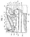
- Fig. 1 is a cross-sectional view showing the general construction of the image forming apparatus 100.
- the image forming apparatus 100 forms an image on a recording medium (e.g. recording paper, an OHP sheet or cloth) by the use of an electrophotographic image forming process in accordance with an image information signal transmitted thereto from a personal computer (or a scanner apparatus or the like) connected to an apparatus main body A for communication therewith.
- a recording medium e.g. recording paper, an OHP sheet or cloth
- the image forming apparatus 100 has a drum-shaped electrophotographic photosensitive member (hereinafter referred to as the "photosensitive drum") 107.
- Image forming will hereinafter be described.
- the surface of the photosensitive drum 107 being rotated is first uniformly charged by a charging roller 108 as a charging member.
- a laser beam conforming to image information is applied from optical means 101 having a laser diode, a polygon mirror, a lens and a reflecting mirror (all being not shown) to the photosensitive drum 107.
- optical means 101 having a laser diode, a polygon mirror, a lens and a reflecting mirror (all being not shown) to the photosensitive drum 107.
- a developer is then supplied to this electrostatic latent image by a developing roller 110 as a developing member.
- a developer image is formed on the photosensitive drum 107.
- a recording medium 102 set in a cassette 103a is conveyed by a feed roller 103b and pairs of conveying rollers 103c, 103d and 103e.
- the recording medium 102 is further fed to a transferring position in a conveying direction indicated by arrow Z along an upper transfer guide 103i and a lower transfer guide 103j.
- the upper transfer guide 103i and the lower transfer guide 103j together constitute a conveying guide for guiding the conveying direction of the recording medium 102.
- a transfer roller 104 as transferring means is disposed in opposed relationship with the photosensitive drum 107. A voltage is applied to this transfer roller 104, whereby the developer image on the photosensitive drum 107 is transferred to the recording medium 102.
- the recording medium 102 to which the developer image has been transferred is conveyed to fixing means 105 through an ante-fixing guide 103f.
- the fixing means 105 is provided with a drive roller 105c and a fixing roller 105b containing a heater 105a therein. It applies heat and pressure to the passing recording medium 102 to thereby fix the developer image on the recording medium 102. Thereafter, the recording medium 102 is conveyed by pairs of rollers 103g and 103h, and is discharged onto a tray 106.
- the feed roller 103b, the pairs of rollers 103c, 103d, 103e, the upper transfer guide 103i, the lower transfer guide 103j, the ante-fixing guide 103f, the pairs of rollers 103g, 103h, etc. together constitute conveying means 103 for conveying the recording medium 102.
- Fig. 2 is a cross-sectional view of the cartridge B.
- the cartridge B has the photosensitive drum 107.
- the photosensitive drum 107 receives a driving force from the apparatus main body A and is rotated thereby.
- the charging roller 108 as a charging member is provided in opposed relationship with the outer peripheral surface of the photosensitive drum 107.
- the charging roller 108 has a voltage (charging bias) applied thereto from the apparatus main body A.
- the charging roller 108 then charges the photosensitive drum 107.
- the charging roller 108 is provided in contact with the photosensitive drum 107.
- the charging roller 108 is driven to rotate by the photosensitive drum 107.
- the charging roller 108 receives a voltage from the apparatus main body A through a charging output electrical contact 144a (see Fig. 6) as a main body electrical contact, and a charging input electrical contact (charging bias contact) 141a (see Fig. 8) as a cartridge electrical contact.
- the charging output electrical contact 144a is an electrical contact the apparatus main body A has.
- the charging input electrical contact (charging bias contact) 141a is an electrical contact the cartridge B has.
- the photosensitive drum 107 is charged by this voltage.
- the cartridge B has the developing roller 110 as a developing member.
- the developing roller 110 supplies a developer "t" to the developing area of the photosensitive drum 107.
- the developing roller 110 develops the electrostatic latent image formed on the photosensitive drum 107, by the use of this developer "t".
- the developing roller 110 contains a magnet roller (stationary magnet) 111 therein.
- a developing blade 112 as a developer amount regulating member is provided in abutting relationship with the peripheral surface of the developing roller 110.
- the developing blade 112 regulates the amount of the developer "t” adhering to the peripheral surface of the developing roller 110. Further, the developing blade 112 imparts triboelectric charges to the developer "t".
- the developer "t” contained in a developer container 114 is carried into a developing chamber 113a by the rotation of agitating members 115 and 116.
- the developing roller 110 to which a voltage (developing bias) has been applied is being rotated.
- a layer of developer “t” to which the triboelectric charges have been imparted by the developing blade 112 is formed on the surface of the developing roller 110.
- the developer "t” formed on the surface of the developing roller 110 moves to the photosensitive drum 107 in conformity with the latent image. Thereby, the latent image is developed.
- the developing roller 110 receives a voltage from the apparatus main body A through a developing output electrical contact 161a (see Fig. 6) as a main body electrical contact, and a developing input electrical contact (developing bias contact) 160a (see Fig. 8) as a cartridge electrical contact.
- the developing roller 110 functions by this voltage and develops the electrostatic latent image.
- the cartridge B according to the present embodiment is provided with a first detecting electrode 190 and a second detecting electrode 191 as developer amount detecting means capable of detecting the remaining amount of the developer "t" in accordance with the consumption thereof.
- the first detecting electrode 190 and the second detecting electrode 191 are provided at locations contacting with the developer. Further, the first detecting electrode 190 and the second detecting electrode 191 are disposed at such locations that the areas of contact thereof with the developer fluctuate as the developer "t" is decreased.
- the first detecting electrode 190 and the second detecting electrode 191 are disposed along the lengthwise direction of the developing roller 110 so as to be opposed to the developing roller 110.
- the cartridge B is provided with a first cartridge remaining amount detecting contact 188a and a second cartridge remaining amount detecting contact 189a as cartridge electrical contacts.
- the first cartridge remaining amount detecting contact 188a is connected to the first detecting electrode 190. Also, the second cartridge remaining amount detecting contact 189a is connected to the second detecting electrode 191.
- the developer image formed on the photosensitive drum 107 is transferred to the recording medium 102 by the transfer roller 104.
- An elastic cleaning blade 117a as a cleaning member is disposed in opposed relationship with the outer peripheral surface of the photosensitive drum 107. The tip end of the cleaning blade 117a abuts against the photosensitive drum 107.
- the cleaning blade 117a removes any developer "t” residual on the photosensitive drum 107.
- the developer "t” removed from the surface of the photosensitive drum 107 by the cleaning blade 117a is contained in a removed developer reservoir 117b.
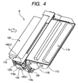
- the cartridge B is constructed by a developing unit 119 and a drum unit 120 being made integral with each other.
- the developing unit 119 has a developing frame member 113 which is a portion of a cartridge frame member B1.
- the developing unit 119 further has the developing roller 110, the developing blade 112, the developing chamber 113a, the developer container 114, the agitating members 115, 116, the first detecting electrode 190, the second detecting electrode 191, etc.
- the drum unit 120 has a drum frame member 118 which is a portion of the cartridge frame member B1.
- the drum unit 120 further has the photosensitive drum 107, the cleaning blade 117a, the removed developer reservoir 117b and the charging roller 108.
- the developing unit 119 and the drum unit 120 are pivotally coupled together by a pin (not shown).
- the developing roller 110 is pressed against the photosensitive drum 107 by a resilient member (not shown) provided between the two units 119 and 120.
- a first right cartridge guide 140R1 and a second right cartridge guide 140R2 as mounting guide members are provided on the lengthwisely one end (the right end as viewed in a direction X in which the cartridge B is mounted) 120R of the drum unit 120.
- the first right cartridge guide 140R1 is a portion of a drum bearing 138 for supporting one end of the photosensitive drum 107.
- a first left cartridge guide 140L1 and a second left cartridge guide 140L2 as mounting guide members are provided on the lengthwisely other end (the left end as viewed in the direction X in which the cartridge B is mounted) 120L of the drum unit 120.
- the first left cartridge guide 140L1 is provided on the outer end portion of a drum shaft 139 for supporting the other end of the photosensitive drum 107.
- a door 109 provided on the apparatus main body A is opened by the operator.
- this side of the door 109 with respect to the direction X in which the cartridge B is mounted is upwardly opened.
- the cartridge B is then detachably mounted with respect to cartridge mounting means 130 provided in the apparatus main body A.
- the cartridge mounting means 130 has a first right main body guide 130R1 and a second right main body guide 130R2 in the right half of the apparatus main body A as viewed in the direction X in which the cartridge B is mounted. Also, the cartridge mounting means 130 has a first left main body guide 130L1 and a second left main body guide 130L2 in the left half of the apparatus main body A as viewed in the direction X in which the cartridge B is mounted.
- the first right cartridge guide 140R1 and the second right cartridge guide 140R2 (Fig. 3) are made parallel to the first right main body guide 130R1 and the second right main body guide 130R2, respectively.
- first left cartridge guide 140L1 and the second left cartridge guide 140L2 are made parallel to the first left main body guide 130L1 and the second left main body guide 130L2, respectively.
- the cartridge B is then inserted into a cartridge mounting portion 130a.
- the first right main body guide 130R1, the second right main body guide 130R2, the first left main body guide 130L1 and the second left main body guide 130L2 are formed on an inner side plate (frame member) 132 of a predetermined thickness.
- the inner side plate 132 is fixed to the inner side of the side plate 145 of the apparatus main body A.
- the inner side plate 132 is cut away into a predetermined shape.
- An upper end surface forming a level difference relative to the side plate 145 provides the first right main body guide 130R1, the second right main body guide 130R2, the first left main body guide 130L1 and the second left main body guide 130L2.
- a groove 131L as a main body guide for guiding the cartridge B into the apparatus main body A is formed between the first left main body guide 130L1 and the lower end surface 132a of the inner side plate 132 opposed substantially parallel thereto.
- This groove 131L plays the role as the main body guide for guiding the cartridge B into the apparatus main body A.
- a groove 130R is formed between the first right main body guide 130R1 and the lower end surface 132a of the inner side plate B opposed substantially parallel thereto. This groove 130R also plays the role as the main body guide.
- the first right cartridge guide 140R1 then fits to the positioning portion 130R1a of the first right main body guide 130R1. Further, the second right cartridge guide 140R2 abuts against the positioning portion 130R2a of the second right main body guide 130R2. Also, the first left cartridge guide 140L1 fits to the first positioning portion 130L1a of the first left main body guide 130L1. Further, the second left cartridge guide 140L2 abuts against the positioning portion 130L2a of the second left main body guide 130L2.
- the cartridge B is positioned on the apparatus main body A. As described above, the cartridge B is detachably mounted on the cartridge mounting portion 130a by the mounting means 130. The cartridge B becomes capable of performing an image forming operation by being mounted on the cartridge mounting portion 130.
- the cartridge mounting portion 130a is a space occupied by the cartridge B positioned relative to the apparatus main body A by the cartridge mounting means 130. Also, the route along which the space occupied by the cartridge B moves to the cartridge mounting portion 130a during the mounting of the cartridge B is the entry route of the cartridge B.
- a coupling 134 as a driving force transmitting portion for transmitting drive to the cartridge B is provided in the apparatus main body A.
- the coupling 134 provided in the apparatus main body A is retracted. Accordingly, the coupling 134 does not hinder the mounting of the cartridge B.
- the coupling 107a (Fig. 3) of the cartridge B as a driving force receiving portion for receiving drive from the apparatus main body A is provided in the cartridge B.
- the cartridge door 109 is closed, the coupling 107a of the cartridge B and the coupling 134 of the apparatus main body A side are connected together. The cartridge B then receives from the apparatus main body A a driving force for rotating the photosensitive drum 107.
- the cartridge B has a charging input electrical contact member 141 and a developing input electrical contact member 160 as cartridge electrical contact members. These electrical contact members are for applying a voltage from the apparatus main body A to the charging roller 108 and the developing roller 110.
- the cartridge B further has a first cartridge remaining amount detecting contact member 188 and a second cartridge remaining amount detecting contact member 189 as cartridge electrical contact members.
- each of the charging input electrical contact member 141 and the developing input electrical contact member 160 is comprised, of a thin metal plate.
- each of the first cartridge remaining detecting contact member 188 and the second cartridge remaining amount detecting contact member 189 is comprised of a metal bar.
- the charging input electrical contact member 141 is provided on the left end portion 120L of the drum unit 120. Also, the charging input electrical contact member 141 is provided so as to be exposed from below and the side of the drum frame member 118 with the cartridge B mounted on the apparatus main body A. The exposed side portion which is apportion of this charging input electrical contact member 141 is a charging input contact 141a as a cartridge electrical contact. The charging input contact 141a is provided more inside the cartridge B than a drum frame member side 118a.
- the developing input electrical contact member 160, the first cartridge remaining amount detecting contact member 188 and the second cartridge remaining amount detecting contact member 189 are provided on the left end portion 190L of a developing unit 190. Further, the developing input electrical contact member 160, the first cartridge remaining amount detecting contact member 188 and the second cartridge remaining amount detecting contact member 189 are provided so as to be exposed from below the developing frame member 113 with the cartridge B mounted on the apparatus main body A.
- the developing input electrical contact member 160 is worked by bending a thin metal plate at an acute angle.
- a developing input electrical contact 160a as a cartridge electrical contact is constructed on the outer tip end of the bent portion thereof.
- a first cartridge remaining amount detecting contact 188a and a second cartridge remaining amount detecting contact 189a are exposed below as respective portions of the first cartridge remaining amount detecting contact member 188 and the second cartridge remaining amount detecting contact member 189.
- the first cartridge remaining amount detecting contact 188a and the second cartridge remaining amount detecting contact 189a are provided along the lengthwise direction of the cartridge B (the axial direction of the photosensitive drum 107).
- the developing input electrical contact 160a, the first cartridge remaining amount detecting contact 188a and the second cartridge remaining amount detecting contact 189a are provided more inside the cartridge B than a developing unit side 119a.
- the charging input electrical contact 141a, the developing input electrical contact 160a, the first cartridge remaining amount detecting contact 188a and the second cartridge remaining amount detecting contact 189a are provided in the named order from downstream to upstream with respect to the direction X in which the cartridge B is mounted. Also, the first cartridge remaining amount detecting contact 188a, the second cartridge reaming amount detecting contact 189a and the developing input electrical contact 160a are provided in the named order from the developing unit side 119a to the inside of the cartridge B.
- the charging input electrical contact 141a, the developing input electrical contact 160a, the first cartridge remaining amount detecting contact 188a and the second cartridge remaining amount detecting contact 189a are electrically connected to the charging roller 108, the developing roller 110, the first detecting electrode 190 and the second detecting electrode 191, respectively, in the interior of the cartridge B.
- a charging output electrical contact member 144 and a developing output electrical contact member 161 as main body electrical contact members for applying a charging voltage and a developing voltage, respectively.
- the charging output electrical contact member 144 and the developing output electrical contact member 161 are electrically connected to the charging input electrical contact 141a and the developing input electrical contact 160a, respectively.
- a first main body remaining amount detecting contact member 163 and a second main body remaining amount detecting contact member 164 as main body electrical contact members.
- the apparatus main body A can apply a voltage to one of the first detecting electrode 190 and the second detecting electrode 191. Also, the apparatus main body A can receive a developer amount detection voltage from the other of the first detecting electrode 190 and the second detecting electrode 191.
- a charging output electrical contact 144a, a developing output electrical contact 161a, a first main body remaining amount detecting contact 163a and a second main body remaining amount detecting contact 164a as main body electrical contacts are provided as respective portions of the main body electrical contact members 144, 161, 163 and 164.
- These main body electrical contacts 144a, 161a, 163a and 164a are provided in the named order from downstream to upstream with respect to the direction X in which the cartridge B is mounted.
- the first main body remaining amount detecting contact 163a, the second main body remaining amount detecting contact 164a and the developing output electrical contact 161a are provided in the named order from the inner side plate 132 to the inside of the cartridge mounting portion 130a.
- the main body electrical contacts 144a, 161a, 163a and 164a are electrically connected to the cartridge electrical contacts 141a, 160a, 188a and 189a, respectively.
- a charging bias is applied through the charging output electrical contact 144a and the charging input electrical contact 141a.
- a developing bias is applied through the developing output electrical contact 161a and the developing input electrical contact 160a.
- developer remaining amount detection can be effected through the first main body remaining amount detecting contact 163a, the second main body remaining amount detecting contact 164a, the first cartridge remaining amount detecting contact 188a and the second cartridge remaining amount detecting contact 189a. Then, the process cartridge becomes capable of operating.
- the developing output electrical contact 161, the first main body remaining amount detecting contact 163 and the second main body remaining amount detecting contact 164 are disposed in the cartridge mounting portion 130a while being covered with electrical contact cover members 151, 153 and 154, respectively.
- the electrical contact cover members 151, 153 and 154 are provided for the developing output contact 161, the first main body remaining amount detecting contact 163 and the second main body remaining amount detecting contact 164, respectively.
- the developing output electrical contact 161a, the first main body remaining amount detecting contact 163a and the second main body remaining amount detecting contact 164a are on the upstream side with respect to the mounting direction of the cartridge B.
- the charging output electrical contact 144a is on the downstream side with respect to the aforementioned mounting direction.
- the operator's hand is liable to have access to the developing output electrical contact 161a, the first main body remaining amount detecting contact 163a and the second main body remaining amount detecting contact 164a.
- the electrical contact cover members 151, 153 and 154 are provided for the developing output contact 161, the first main body remaining amount detecting contact 163 and the second main body remaining amount detecting contact 164, respectively.
- a similar construction can also be applied to the charging output electrical contact member 144.
- Fig. 9 typically shows the mode of connection of the cartridge electrical contacts 160a, 188a and 189a to the main body electrical contacts 161a, 163a and 164a.
- the respective cartridge electrical contacts 160a, 188a and 189a move as indicated by dot-and-dash lines in Fig. 9.
- the cartridge electrical contacts 160a, 188a and 189a are electrically connected to the main body electrical contacts 161a, 163a and 164a, respectively.
- FIG. 9 is a view of the cartridge B and the developing output electrical contact member 161, the first remaining amount detecting contact member 163 and the second remaining amount detecting contact member 164 provided in the apparatus main body A as they are seen from the right side as viewed in the direction in which the cartridge B is mounted.
- the cartridge B is inserted in the direction of arrow X along the aforedescribed cartridge mounting means 130 and is mounted on the apparatus main body A. Then, the cartridge electrical contact members 166, 188 and 189 contact with the main body electrical contact members 161, 163 and 164, respectively, with moderate spring pressure.
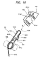
- Figs. 10, 11A and 11B describe the electrical contact cover members (hereinafter referred to as the "contact covers") 151, 153 and 154 attached to the developing output electrical contact member 161, the first main body remaining amount detecting contact member 163 and the second main body remaining amount detecting contact member 164, respectively.
- the contact covers electrical contact cover members
- the developing output electrical contact member 161, the first main body remaining amount detecting contact member 163 and the second main body remaining amount detecting contact member 164 are of the same construction. Also, the contact covers 151, 153 and 154 attached to these respective electrical contacts are substantially of the same construction. Accordingly, description will hereinafter be made of the developing output electrical contact member (hereinafter, in the present embodiment, simply referred to as the "main body contact member") 161 as a representative example, and the contact cover 151 attached thereto.
- Fig. 10 shows the main body contact member 161 and the contact cover 151 as they are separated from each other.
- Fig. 11A shows the right side of the main body contact member 161 with the contact cover 151 attached thereto when it is seen in the direction in which the cartridge B is mounted.
- Fig. 11B shows the left side of the main body contact member 161 with the contact cover 151 attached thereto when it is seen in the direction in which the cartridge is mounted.
- the main body contact member 161 is formed by a torsion coil spring which is a resilient member.
- the main body contact member 161 is mounted on a shaft 132b provided in the inner side plate (frame member) 132 of the apparatus main body A.
- One arm portion of the main body contact member 161 forms a U-shaped portion 161A bent into a substantially U-shape.
- the other arm portion (base) 161b of the main body contact member (torsion coil spring) 161 is connected to an electric circuit (not shown) in the interior of the apparatus main body A.
- the developing output electrical contact (hereinafter, in the present embodiment, simply referred to as the "main body contact”) 161a as a main body electrical contact is provided on the straight portion 161B of the base 161b side of the U-shaped portion 161A.
- the main body contact 161a as a main body electrical contact is made movable relative to the apparatus main body A.
- the main body contact 161a contacts with and is electrically connected to the developing input electrical contact (hereinafter, in the present embodiment, simply referred to as the "cartridge contact”) 160a provided in the cartridge B, with the cartridge B mounted on the apparatus main body A.
- the cartridge contact 160a is the contact of the developing input electrical contact member (hereinafter, in the present embodiment, simply referred to as the "cartridge contact member”) 160.
- the contact cover 151 is attached to the main body contact member 161 to cover the U-shaped portion 161A of the main body contact member 161.
- the contact cover 151 covers substantially the whole of the U-shaped portion 161A.
- the contact cover 151 is put on the main body contact member 161 in the direction of arrow S. Thereby, the contact cover 151 is attached to the main body contact member 161. In the present embodiment, owing to the snap-fit shape of the main body contact member 161, the contact cover 151 does not slip out from the main body contact member 161. Further, the contact cover 151 is supported for movement in the direction of arrow T (Fig. 11A) relative to the main body contact member 161.
- the direction of movement of the main body contact 161a relative to the apparatus main body A is V-direction. This V-direction is substantially perpendicular to the direction of arrow T.
- the material of the contact cover 151 may preferably be a non-electrically conductive one in order to prevent leak.
- a movable portion 161C is constructed on the end 161g side of the U-shaped portion 161A of the main body contact 161.
- On the movable portion 161C there is constructed an inclined portion 161d widely spaced apart from the straight portion 161B toward the end 161g. That portion of this inclined portion 161d which is most widely spaced apart from the straight portion 161B is a top 161e.
- a restraining portion 161f is provided from the top 161e toward the straight portion 161B.
- the restraining portion 161f is substantially perpendicular from the top 161e to the straight portion 161B.
- the end 161g is substantially parallel to the straight portion 161B further from this restraining portion 161f.
- the contact cover 151 is provided with an opening portion 151c narrower than the spacing between the top 161e and straight portion 161B of the main body contact member 161 in a direction orthogonal to the direction S of attachment to the main body contact member 161.
- the width of this opening portion 151c is substantially the same as the line diameter of the main body contact member (torsion coil spring). Accordingly, the main body contact member 161 is flexed as indicated by dots-and-dash line in Fig. 10 against the resilient force of the U-shaped portion 161A. In that state, the main body contact member 161 is inserted into the opening portion 151c of the contact cover 151.
- the top 161e of the inclined portion 161d clears the opening portion 151c
- the movable portion 161C is restored to its original shape by the resilient force of restitution of the U-shaped portion 161A.
- a bumping portion 151g for bumping against the tip end 161h of the main body contact member 161 is provided inside the contact cover 151.
- the width W1 from the bumping portion 151g to the edge portion 151f of the opening portion 151c is greater than the width W2 from the tip end 161h to the restraining portion 161f in the same direction.
- the contact cover 151 is movable relative to the main body contact member 161.
- the restraining portion 161f abuts against the edge portion 151f. Therefore, it never happens that the contact cover 151 inadvertently slip out from the main body contact member 161.
- a regulating portion 151d is provided inside the contact cover 151.
- the regulating portion 151d regulates the position of the straight portion 161B of the U-shaped portion 161A.
- This regulating portion 151d makes the straight portion 161B parallel to the inner side of the contact cover 151. Then, a portion of the straight portion 161B is exposed to the cut-away portion 151a.
- the tip end 161h of the U-shaped portion 161A clears this regulating portion 151d.
- a side stop 151e is provided so that the contact cover 151 may not break away sideways.
- the side stop 151e is provided substantially in parallelism to a plane formed by the U-shaped portion 161A of the main body contact member 161. This side stop 151e holds the main body contact member 161 relative to the inner side of the contact cover 151.
- the contact cover 151 is provided with a cut-away portion (opening portion) 151a.
- the lower end portion of this cut-away portion 151a which communicates with the interior of the contact cover 151 is an exposed portion 151a1.
- This exposed portion 151a1 exposes the main body contact 161a to the outside of the contact cover 151. Thereby, the exposed portion 151a1 permits the connection between the cartridge contact 160a and the main body contact 161a.
- the cut-away portion 151a is formed to a size at which the cartridge contact 160a and the main body contact 161a can contact with each other. That is, the cut-away portion 151a corresponds to the size of the cartridge contact member 160.
- the cartridge contact member 160 When the cartridge B is mounted on the apparatus main body A, at least a portion of the cartridge contact member 160 enters this cut-away portion 151a. Then, in the exposed portion 151a1, the cartridge contact 160a contacts with the contact portion (main body contact) 161a of the main body contact member 161.
- the contact cover 151 is provided with a first guide portion 151b1 and a second guide portion 151b2 as receiving portions abutting against an abutting portion (in the present embodiment, the cartridge contact member 160) the cartridge B has.
- the first guide portion 151b1 and the second guide portion 151b2 are provided on the inner side wall of the cut-away portion 151a.
- the first guide portion 151b1 and the second guide portion 151b2 are provided on the end portion of the exposed portion 151a1.
- the first guide portion 151b1 and the second guide portion 151b2 are pushed by the abutting portion of the cartridge B, whereby the contact cover 151 is moved relative to the main body contact member 161. Accordingly, the exposed portion 151a1 is also moved relative to the main body contact member 161. Then, in the exposed portion 151a1, the cartridge contact 160a and the main body contact 161a are electrically connected together. That is, in operative association with the connection of the cartridge B to the apparatus main body A, the cartridge contact 160a and the main body contact 161a are electrically connected together.
- the cut-away portion 151a is provided so as to face in a direction in which the cartridge B comes in during the mounting of the cartridge B. Further, the cut-away portion 151a is provided so that in the exposed portion 151a1, the straight portion 161B of the main body contact member 161 may be exposed.
- the cut-away portion 151a is preferably smaller than the tip end of a finger. Further, the cut-away portion 151a is of a shape larger than that portion of the cartridge contact member 160 which comes thereinto.
- the first guide portion 151b1 and the second guide portion 151b2 are the inner sides of the cut-away portion 151a. Also, the first guide portion 151b1 and the second guide portion 151b2 are opposed to each other along the direction S of movement of the contact cover 151. Also, the spacing between the first guide portion 151b1 and the second guide portion 151b2 in the direction S of movement becomes narrower toward the exposed portion 151a1.
- the first guide portion 151b1 and the second guide portion 151b2 when seen from the mounting direction X of the cartridge B, are constituted by the inner sides of an opening portion continuous to the exposed portion 151a1 (i.e., the straight portion 161B of the main body contact member 161 in the interior of the contact cover 151). Therefore, the cartridge contact 160a is smoothly directed to the main body contact 161a. Further, the width of the opening portion becomes narrower toward the exposed portion 151a1 (i.e., the straight portion 161B of the main body contact member 161 in the interior of the contact cover 151).
- the direction of movement of the contact cover 151 (the direction of movement of the contact cover 151 relative to the apparatus main body A) is substantially the same direction as the mounting direction X of the cartridge B.
- the width of the upper end of the cut-away portion 151a in the direction T of movement of the contact cover 151 relative to the main body electrical contact member 161 (the maximum spacing W3 between the first guide portion 151b1 and the second guide portion 151b2) is 4 to 8 mm.
- the width of the lower end portion of the cut-away portion in the same direction (the width W4 of the exposed portion 151a1) is 2 to 4 mm.
- the height H1 from the upper end to the lower end portion of the cut-away portion 151a (the exposed portion 151a1) is 2 to 3 mm.
- the main body electrical contact member 161 is exposed from one side of the contact cover 151. Also, however, the inner side plate 132 of the apparatus main body A is located on this side of the contact cover 161. Therefore, the main body electrical contact member 161 is substantially hermetically sealed. However, not only in the present embodiment, this side of the contact cover 151 can be made into a substantially hermetically sealed shape in conformity with the mode of disposition of the contact cover 151 in the apparatus main body A. As shown in Fig. 11A, the other side of the contact cover 151 is substantially hermetically sealed.
- the size of the cut-away portion 151a is smaller than the tip ends of the fingers and larger than the cartridge contact 160a. Therefore, it becomes substantially impossible for the operator's fingers to touch the contact portion (main body contact) 161a of the cartridge contact member 160.
- Fig. 12 is a side view showing the movement locus of the cartridge contact member 160 and the movement loci of the contact cover 151 and the main body contact member 161 during the mounting of the cartridge B onto the apparatus main body A.
- the cartridge contact member 160 is shown typically as a circular side.
- Fig. 13 is a side view of the interior of the apparatus main body A in the course of the mounting of the cartridge B onto the apparatus main body A.
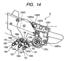
- Fig. 14 is a side view of the interior of the apparatus main body A with the cartridge B mounted on the apparatus main body A.
- the cartridge B is moved in the direction of arrow X along the aforedescribed cartridge mounting means 130 by the operator's mounting operation (Fig. 13).
- the cartridge contact member 160 strikes against the first guide portion 151b1 provided at the entrance of the cut-away portion 151a. While in Fig. 12, it strikes against the first guide portion 151b1, it strikes against second guide 151b2 in some cases. As described above, in the present embodiment, the cartridge contact member 160 abuts against the guide portions 151b1 and 151b2 as receiving portions. In operative association with the mounting operation of the cartridge B, the guide portions 151b1 and 151b2 have the function as cartridge abutting portions for moving the contact cover 151.
- the cartridge contact member 160 moves the contact cover 151. That is, the first guide portion 151b1 and the second guide portion 151b2 become thinner forwardly toward the exposed portion 151a1.
- the contact cover 151 is moved as indicated by arrow T1.
- the contact cover 151 is moved in a forward direction with respect to the mounting direction X of the cartridge B.
- the alignment of the contact cover 151 with the main body contact member 161 is roughly effected.
- the mounting guide members 140R1, 140R2, 140L1 and 140L2 of the cartridge B are positioned relative to the cartridge mounting means 130.
- the cartridge contact member 160 further moves the contact cover 151 as indicated by arrow T2.
- the cartridge contact member 160 then fits into the cut-away portion 151a.
- the contact cover 151 is positioned at a predetermined position.
- the main body contact 151a which is a portion exposed from the exposed portion 151a1 of the contact cover 151 and the contact portion (cartridge contact) 160a of the cartridge contact member 160 contact with each other.
- the image forming apparatus 100 becomes capable of forming an image (Fig. 14).
- the cartridge contact member 160 when the cartridge B is being mounted on the apparatus main body A, the cartridge contact member 160 abuts against the contact cover 151. Thereby, the cartridge contact member has the function as electrical contact cover member positioning means for regulating the position of the contact cover 151.
- the main body contact member 161 is formed by a torsion coil spring.
- this torsion coil spring is designed to flex in the mounting direction X of the cartridge B. Therefore, in a state in which the cartridge B is mounted on the apparatus main body A, the spring is brought down in the direction of arrow U (Fig. 12). Thereby, the spring is compressed and the contact members contact with each other with predetermined contact pressure.
- the cartridge contact member 160 abuts against the first guide portion 151b1. It has been described that at that time, the contact cover 151 moves in the forward direction (T1, T2) with respect to the mounting direction X of the cartridge B. However, this is not restrictive. In some cases, conversely the cartridge contact member 160 abuts against the second guide portion 151b2 in conformity with the position or the like of the contact cover 151 relative to the main body contact member 161 when the cartridge B is mounted. Further, there is also a case where the contact cover 151 moves in a direction opposite to the mounting direction X of the cartridge B.
- the contact cover 151 in a state in which the cartridge B is not mounted on the apparatus main body A, the contact cover 151 is lowered downwardly by gravity. Further, the tip end 151h of the contact member abuts against the bumping portion 151g. When the cartridge B is then mounted on the apparatus main body A, the contact cover 151 is moved in the forward direction with respect to the mounting direction X of the cartridge B. Also, as previously described, the contact cover 151 is movable in the direction of arrow T relative to the main body contact member 161. Further, the main body contact 161a is movable in the direction of arrow V relative to the apparatus main body A. The direction of arrow V is substantially perpendicular to the direction of arrow T.
- the exposed portion 151a1 is movable in the direction of arrow V and the direction of arrow T perpendicular thereto. Accordingly, the degree of freedom of the movement of the exposed portion 151a1 can be secured by an inexpensive construction. Consequently, the reliability of the electrical connection between the main body contact 161a and the cartridge contact 160a can be improved.
- the constructions and operations of the contact covers 153, 154 and the main body contact members 163, 164 are similar to those of the developing output contact member 151 and the contact cover 151 thereof.
- a charging bias circuit E1 generates a negative DC voltage and an AC voltage. A voltage comprising the above-mentioned voltages superimposed one upon the other is then applied to the charging roller 108. The charging roller 108 receives this voltage and charges the photosensitive drum 107. The charging bias circuit E1 applies a negative DC voltage also to the fixing roller 105b through the drive roller 105c.
- a developing bias circuit E2 generates a negative DC voltage and an AC voltage.
- a voltage comprising the aforementioned voltages superimposed one upon the other is then applied to the developing roller 110 and the second detecting electrode 191.
- the developing roller 110 receives this voltage and develops the electrostatic latent image by a developer.
- a transferring bias circuit E3 generates a positive or negative DC voltage. Then, it applies the positive or negative DC voltage to the transfer roller 104.
- the first detecting electrode 190 is connected to the detecting circuit of a developer remaining amount detecting circuit E4, and an output voltage (developer amount detection voltage) when a voltage has been applied to the second detecting electrode 191 and the developing roller 110 is inputted thereto.
- a reference voltage generating circuit generates a reference voltage in detecting the remaining amount of the developer, by the use of a current applied from the developing bias circuit E2. Then, the detecting circuit outputs the difference between the reference voltage and the developer amount detection voltage as the detected value of the remaining amount of the developer to a CPU. The information of the thus detected remaining amount of the developer is reported to the use by a display portion (not shown) or the like provided on the image forming apparatus main body A.
- a voltage from a voltage source S is supplied to the charging roller 108 through the charging bias circuit E1. Also, the voltage from the voltage source S is supplied to the fixing roller 105b and the drive roller 105c through the charging bias circuit E1. Further, the voltage from the voltage source S is supplied to the developing roller 110 and the second detecting electrode 191 through the developing bias circuit E2. Also, the voltage from the voltage source S is supplied to the transfer roller 104 through the transfer charging bias circuit E3.
- circuits E1, E2 and E3 have their ON and OFF controlled by instructions from a CPC 200 provided on a circuit board EC.
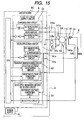
- the circuit board EC mounted on the apparatus main body A will now be described with reference to Fig. 15. This circuit board EC is mounted below the cartridge mounting portion 130a.
- the circuit board EC has the CPU 200 and an electric circuit E (power supply circuit) E.
- the voltage source S is connected to the circuit board EC, i.e., the electric circuit E.
- the electric circuit E is comprised of the charging bias circuit E1, the developing bias circuit E2, the transfer charging bias circuit E3 and the developer remaining amount detecting circuit E4.
- the charging bias circuit E1 generates a negative DC voltage and an AC voltage. It applies to the charging roller 108 a voltage comprising the aforementioned voltages superimposed one upon the other. The charging roller 108 receives this voltage and charges the photosensitive drum 107. The charging bias circuit E1 also applies the negative DC voltage to the fixing roller 105b through the drive roller 105c.
- the developing bias circuit E2 generates a negative DC voltage and an AC voltage. It applies to the developing roller 110 and the second detecting electrode a voltage comprising the aforementioned voltages superimposed one upon the other. The developing roller 110 receives this voltage and develops the electrostatic latent image by the developer.
- the transferring bias circuit E3 generates a positive or negative DC voltage. It appears the positive or negative DC voltage to the transfer roller 104.
- the first detecting electrode 190 is connected to the detecting circuit of the developer remaining amount detecting circuit E4, and an output voltage (developer amount detection voltage) when a voltage has been applied to the second detecting electrode 191 and the developing roller 110 is inputted.
- the reference voltage generating circuit generates a reference voltage in detecting the remaining amount of the developer, by the use of a current applied from the developing bias circuit E2. Then, the detecting circuit outputs the difference between the reference voltage and the developer amount detection voltage as the detected value of the remaining amount of the developer to the CPU. The thus detected information of the remaining amount of the developer is reported to the use by a display portion (not shown) or the like provided in the image forming apparatus main body A.
- the voltage from the voltage source S is supplied to the charging roller 108 through the charging bias circuit E1. Also, the voltage from the voltage source S is supplied to the fixing roller 105b and the drive roller 105c through the charging bias circuit E1. Further, the voltage from the voltage source S is supplied to the developing roller 110 and the second detecting electrode 191 through the developing bias circuit E2. Also, the voltage from the voltage source S is supplied to the transfer roller 104 through the transfer charging bias circuit E3.
- circuits have their ON and OFF controlled by the instructions from the CPU 200 provided on the circuit board EC.
- the reliability of the electrical connection between the electrical contacts the process cartridge has and the electrical contacts provided in the electrophotographic image forming apparatus main body can be improved.
- an electrophotographic image forming apparatus and a cartridge or a process cartridge in which in operative association with the operation of mounting the cartridge on the electrophotographic image forming apparatus main body, electrical contact cover members are moved relative to main body electrical contact members, whereby cartridge electrical contacts and main body electrical contacts are electrically connected together.
Landscapes
- Engineering & Computer Science (AREA)
- Computer Vision & Pattern Recognition (AREA)
- Physics & Mathematics (AREA)
- General Physics & Mathematics (AREA)
- Electrophotography Configuration And Component (AREA)
Applications Claiming Priority (4)
| Application Number | Priority Date | Filing Date | Title |
|---|---|---|---|
| JP2004055461 | 2004-02-27 | ||
| JP2004055461 | 2004-02-27 | ||
| JP2004166155A JP4035516B2 (ja) | 2004-02-27 | 2004-06-03 | 電子写真画像形成装置 |
| JP2004166155 | 2004-06-03 |
Publications (2)
| Publication Number | Publication Date |
|---|---|
| EP1596257A1 true EP1596257A1 (fr) | 2005-11-16 |
| EP1596257B1 EP1596257B1 (fr) | 2017-11-08 |
Family
ID=34889410
Family Applications (1)
| Application Number | Title | Priority Date | Filing Date |
|---|---|---|---|
| EP04015142.5A Expired - Lifetime EP1596257B1 (fr) | 2004-02-27 | 2004-06-28 | Appareil pour connexion électrique entre un appareil de formation d'images et son unité de traitement |
Country Status (5)
| Country | Link |
|---|---|
| US (2) | US7209676B2 (fr) |
| EP (1) | EP1596257B1 (fr) |
| JP (1) | JP4035516B2 (fr) |
| KR (1) | KR100693232B1 (fr) |
| CN (1) | CN100442152C (fr) |
Families Citing this family (19)
| Publication number | Priority date | Publication date | Assignee | Title |
|---|---|---|---|---|
| JP3858875B2 (ja) * | 2003-08-25 | 2006-12-20 | 村田機械株式会社 | 現像器及びそれを備えた画像形成装置 |
| JP4387932B2 (ja) * | 2003-12-09 | 2009-12-24 | キヤノン株式会社 | プロセスカートリッジ及び電子写真画像形成装置 |
| JP4387933B2 (ja) * | 2003-12-09 | 2009-12-24 | キヤノン株式会社 | プロセスカートリッジ及び電子写真画像形成装置 |
| JP4095589B2 (ja) * | 2004-02-27 | 2008-06-04 | キヤノン株式会社 | 電子写真画像形成装置、及びプロセスカートリッジ |
| US20070154232A1 (en) * | 2006-01-04 | 2007-07-05 | Lexmark International, Inc. | Contacting removable printer cartridges |
| JP4577377B2 (ja) * | 2008-02-26 | 2010-11-10 | ブラザー工業株式会社 | 画像形成装置 |
| CN201340516Y (zh) * | 2008-11-19 | 2009-11-04 | 珠海天威飞马打印耗材有限公司 | 充电辊导电片和具有该导电片的显影剂盒 |
| JP5743178B2 (ja) * | 2009-10-13 | 2015-07-01 | 株式会社リコー | 画像形成装置 |
| JP5136601B2 (ja) * | 2010-06-24 | 2013-02-06 | ブラザー工業株式会社 | タンデム型ドラムユニット |
| JP5644391B2 (ja) * | 2010-11-09 | 2014-12-24 | 富士ゼロックス株式会社 | 電気接続構造、画像形成装置 |
| CN103293907B (zh) * | 2012-03-02 | 2016-06-29 | 珠海艾派克科技股份有限公司 | 一种显影盒 |
| JP6136603B2 (ja) * | 2013-06-07 | 2017-05-31 | ブラザー工業株式会社 | カートリッジ |
| US9367019B2 (en) * | 2014-06-30 | 2016-06-14 | Kyocera Document Solutions Inc. | Electric wire member and image forming apparatus including the same |
| JP6365462B2 (ja) * | 2015-08-17 | 2018-08-01 | 京セラドキュメントソリューションズ株式会社 | 画像形成装置 |
| JP6582972B2 (ja) * | 2015-12-25 | 2019-10-02 | ブラザー工業株式会社 | 現像カートリッジ |
| KR102380993B1 (ko) | 2016-08-26 | 2022-03-30 | 캐논 가부시끼가이샤 | 드럼 유닛, 카트리지, 전자 사진 화상 형성 장치 및 커플링 부재 |
| JP6896562B2 (ja) * | 2016-11-18 | 2021-06-30 | キヤノン株式会社 | 現像装置、プロセスカートリッジ及び画像形成装置 |
| JP2023077485A (ja) * | 2021-11-25 | 2023-06-06 | キヤノン株式会社 | 画像形成装置 |
| CN119620566A (zh) * | 2024-12-31 | 2025-03-14 | 珠海奔图电子有限公司 | 导电部件、处理盒和图像形成装置 |
Citations (5)
| Publication number | Priority date | Publication date | Assignee | Title |
|---|---|---|---|---|
| EP0370818A2 (fr) * | 1988-11-25 | 1990-05-30 | Xerox Corporation | Connexion électrique à deux éléments |
| JPH0777921A (ja) | 1993-09-09 | 1995-03-20 | Fuji Xerox Co Ltd | 画像形成装置のプロセスカートリッジ装着装置 |
| US6249660B1 (en) * | 1996-09-09 | 2001-06-19 | Minolta Co., Ltd. | Imaging cartridge for use in an image forming apparatus including detachable electrode member |
| US6351620B1 (en) * | 1998-10-23 | 2002-02-26 | Canon Kabushiki Kaisha | Process cartridge having guide projections and image forming apparatus using same |
| US20030108355A1 (en) * | 2000-08-25 | 2003-06-12 | Canon Kabushiki Kaisha | Memory member, unit, process cartridge and electrophotographic image forming apparatus |
Family Cites Families (19)
| Publication number | Priority date | Publication date | Assignee | Title |
|---|---|---|---|---|
| JP3285413B2 (ja) | 1993-04-28 | 2002-05-27 | キヤノン株式会社 | 感光体ドラム及びプロセスカートリッジ及び画像形成装置 |
| JP3236124B2 (ja) | 1993-04-28 | 2001-12-10 | キヤノン株式会社 | プロセスカートリッジ及び画像形成装置及びプロセスカートリッジのトナーテープ取り付け方法 |
| JP3320144B2 (ja) | 1993-04-28 | 2002-09-03 | キヤノン株式会社 | プロセスカートリッジ及び画像形成装置及び画像形成システム |
| JP3285417B2 (ja) | 1993-04-28 | 2002-05-27 | キヤノン株式会社 | プロセスカートリッジ及び画像形成装置及び画像形成システム |
| JPH06313996A (ja) | 1993-04-28 | 1994-11-08 | Canon Inc | プロセスカートリッジ及び画像形成装置及びプロセスカートリッジの組み立て方法及び現像装置 |
| JP3323696B2 (ja) | 1995-06-13 | 2002-09-09 | キヤノン株式会社 | アース部材及び電子写真感光体ドラム及びプロセスカートリッジ及び電子写真画像形成装置 |
| JP2000066498A (ja) | 1998-08-21 | 2000-03-03 | Canon Inc | 電子写真画像形成装置及びプロセスカートリッジ |
| JP3530751B2 (ja) | 1998-10-09 | 2004-05-24 | キヤノン株式会社 | プロセスカートリッジ及び電子写真画像形成装置 |
| JP3530752B2 (ja) | 1998-10-09 | 2004-05-24 | キヤノン株式会社 | 電子写真画像形成装置、プロセスカートリッジ、現像装置、現像剤供給容器及び測定部品 |
| US6311026B1 (en) | 1998-11-13 | 2001-10-30 | Canon Kabushiki Kaisha | Process cartridge and image forming apparatus including means for detecting mounting of the process cartridge to main body of image forming apparatus, and process cartridge and developer cartridge including positioning portion |
| JP3745231B2 (ja) | 2000-01-13 | 2006-02-15 | キヤノン株式会社 | プロセスカートリッジ及び電子写真画像形成装置 |
| JP2001290355A (ja) | 2000-04-06 | 2001-10-19 | Canon Inc | 現像装置、プロセスカートリッジ及び電子写真画像形成装置 |
| US6587650B2 (en) | 2000-07-28 | 2003-07-01 | Canon Kabushiki Kaisha | Electrophotographic image forming apparatus, process cartridge, and developing device having developer amount detector |
| JP3697168B2 (ja) | 2001-03-09 | 2005-09-21 | キヤノン株式会社 | プロセスカートリッジおよび電子写真画像形成装置 |
| JP3840063B2 (ja) * | 2001-04-27 | 2006-11-01 | キヤノン株式会社 | プロセスカートリッジ |
| JP2003255804A (ja) | 2001-12-07 | 2003-09-10 | Canon Inc | プロセスカートリッジの再生産方法および現像装置の再生産方法 |
| JP2003255806A (ja) | 2002-02-28 | 2003-09-10 | Canon Inc | プロセスカートリッジ、現像装置および画像形成装置 |
| JP2004061595A (ja) | 2002-07-25 | 2004-02-26 | Canon Inc | 画像形成装置及びプロセスカートリッジ |
| JP3625470B1 (ja) * | 2003-09-30 | 2005-03-02 | キヤノン株式会社 | プロセスカートリッジ、及び、電子写真画像形成装置 |
-
2004
- 2004-06-03 JP JP2004166155A patent/JP4035516B2/ja not_active Expired - Fee Related
- 2004-06-14 US US10/865,758 patent/US7209676B2/en not_active Expired - Lifetime
- 2004-06-28 EP EP04015142.5A patent/EP1596257B1/fr not_active Expired - Lifetime
- 2004-08-10 CN CNB2004100583209A patent/CN100442152C/zh not_active Expired - Fee Related
- 2004-09-07 KR KR1020040071053A patent/KR100693232B1/ko not_active Expired - Fee Related
-
2006
- 2006-04-20 US US11/407,153 patent/US7200347B2/en not_active Expired - Lifetime
Patent Citations (5)
| Publication number | Priority date | Publication date | Assignee | Title |
|---|---|---|---|---|
| EP0370818A2 (fr) * | 1988-11-25 | 1990-05-30 | Xerox Corporation | Connexion électrique à deux éléments |
| JPH0777921A (ja) | 1993-09-09 | 1995-03-20 | Fuji Xerox Co Ltd | 画像形成装置のプロセスカートリッジ装着装置 |
| US6249660B1 (en) * | 1996-09-09 | 2001-06-19 | Minolta Co., Ltd. | Imaging cartridge for use in an image forming apparatus including detachable electrode member |
| US6351620B1 (en) * | 1998-10-23 | 2002-02-26 | Canon Kabushiki Kaisha | Process cartridge having guide projections and image forming apparatus using same |
| US20030108355A1 (en) * | 2000-08-25 | 2003-06-12 | Canon Kabushiki Kaisha | Memory member, unit, process cartridge and electrophotographic image forming apparatus |
Non-Patent Citations (1)
| Title |
|---|
| PATENT ABSTRACTS OF JAPAN vol. 1995, no. 06 31 July 1995 (1995-07-31) * |
Also Published As
| Publication number | Publication date |
|---|---|
| CN100442152C (zh) | 2008-12-10 |
| JP2005275338A (ja) | 2005-10-06 |
| CN1661484A (zh) | 2005-08-31 |
| US7200347B2 (en) | 2007-04-03 |
| EP1596257B1 (fr) | 2017-11-08 |
| KR20050087710A (ko) | 2005-08-31 |
| US7209676B2 (en) | 2007-04-24 |
| KR100693232B1 (ko) | 2007-03-12 |
| JP4035516B2 (ja) | 2008-01-23 |
| US20050191079A1 (en) | 2005-09-01 |
| US20060188285A1 (en) | 2006-08-24 |
Similar Documents
| Publication | Publication Date | Title |
|---|---|---|
| EP1596257B1 (fr) | Appareil pour connexion électrique entre un appareil de formation d'images et son unité de traitement | |
| US7239823B2 (en) | Electrophotographic image forming apparatus, process cartridge and discharge preventing mechanism | |
| US7937020B2 (en) | Electrophotographic image forming apparatus | |
| US8213828B2 (en) | Electrophotographic image forming apparatus and process cartridge mounted thereto having contacts electrically connecting with an electrical contact | |
| US6993264B2 (en) | Process cartridge and electrophotographic image forming apparatus | |
| US7567769B2 (en) | Electrophotographic color image forming apparatus | |
| US7660549B2 (en) | Electrophotographic image forming apparatus | |
| US7079783B2 (en) | Developing cartridge detachable from image forming device | |
| JP4833117B2 (ja) | 潜像担持体ユニット及び画像形成装置 | |
| US20070092286A1 (en) | Process cartridge and electrophotographic image forming apparatus | |
| US8781354B2 (en) | Image-forming apparatus | |
| JP2003195723A (ja) | 画像形成装置 | |
| US7725063B2 (en) | Image-forming device with interlockingly movable two paper guide members | |
| US20240385571A1 (en) | Image forming apparatus and cartridge | |
| US20250116964A1 (en) | Cartridge and image forming apparatus | |
| JP2005258145A (ja) | プロセスカートリッジ | |
| JP2005345940A (ja) | 画像形成装置 | |
| HK1062049B (en) | Developing cartridge detachable from image forming device |
Legal Events
| Date | Code | Title | Description |
|---|---|---|---|
| PUAI | Public reference made under article 153(3) epc to a published international application that has entered the european phase |
Free format text: ORIGINAL CODE: 0009012 |
|
| AK | Designated contracting states |
Kind code of ref document: A1 Designated state(s): AT BE BG CH CY CZ DE DK EE ES FI FR GB GR HU IE IT LI LU MC NL PL PT RO SE SI SK TR |
|
| AX | Request for extension of the european patent |
Extension state: AL HR LT LV MK |
|
| 17P | Request for examination filed |
Effective date: 20060516 |
|
| AKX | Designation fees paid |
Designated state(s): DE FR GB |
|
| 17Q | First examination report despatched |
Effective date: 20071122 |
|
| GRAP | Despatch of communication of intention to grant a patent |
Free format text: ORIGINAL CODE: EPIDOSNIGR1 |
|
| INTG | Intention to grant announced |
Effective date: 20170522 |
|
| RIN1 | Information on inventor provided before grant (corrected) |
Inventor name: TANAKA, NORIAKI Inventor name: KAWAGUCHI, HIDESHI Inventor name: YOKOI, AKIYOSHI |
|
| GRAS | Grant fee paid |
Free format text: ORIGINAL CODE: EPIDOSNIGR3 |
|
| GRAA | (expected) grant |
Free format text: ORIGINAL CODE: 0009210 |
|
| AK | Designated contracting states |
Kind code of ref document: B1 Designated state(s): DE FR GB |
|
| REG | Reference to a national code |
Ref country code: GB Ref legal event code: FG4D |
|
| REG | Reference to a national code |
Ref country code: DE Ref legal event code: R096 Ref document number: 602004052016 Country of ref document: DE |
|
| REG | Reference to a national code |
Ref country code: DE Ref legal event code: R097 Ref document number: 602004052016 Country of ref document: DE |
|
| PLBE | No opposition filed within time limit |
Free format text: ORIGINAL CODE: 0009261 |
|
| STAA | Information on the status of an ep patent application or granted ep patent |
Free format text: STATUS: NO OPPOSITION FILED WITHIN TIME LIMIT |
|
| 26N | No opposition filed |
Effective date: 20180809 |
|
| GBPC | Gb: european patent ceased through non-payment of renewal fee |
Effective date: 20180628 |
|
| PG25 | Lapsed in a contracting state [announced via postgrant information from national office to epo] |
Ref country code: GB Free format text: LAPSE BECAUSE OF NON-PAYMENT OF DUE FEES Effective date: 20180628 Ref country code: FR Free format text: LAPSE BECAUSE OF NON-PAYMENT OF DUE FEES Effective date: 20180630 |
|
| PGFP | Annual fee paid to national office [announced via postgrant information from national office to epo] |
Ref country code: DE Payment date: 20190830 Year of fee payment: 16 |
|
| REG | Reference to a national code |
Ref country code: DE Ref legal event code: R119 Ref document number: 602004052016 Country of ref document: DE |
|
| PG25 | Lapsed in a contracting state [announced via postgrant information from national office to epo] |
Ref country code: DE Free format text: LAPSE BECAUSE OF NON-PAYMENT OF DUE FEES Effective date: 20210101 |