EP1596263A1 - Integrierter Träger mit mehrmotorigem Regler - Google Patents
Integrierter Träger mit mehrmotorigem Regler Download PDFInfo
- Publication number
- EP1596263A1 EP1596263A1 EP05252009A EP05252009A EP1596263A1 EP 1596263 A1 EP1596263 A1 EP 1596263A1 EP 05252009 A EP05252009 A EP 05252009A EP 05252009 A EP05252009 A EP 05252009A EP 1596263 A1 EP1596263 A1 EP 1596263A1
- Authority
- EP
- European Patent Office
- Prior art keywords
- motor
- controller
- motors
- dsp
- gate driver
- Prior art date
- Legal status (The legal status is an assumption and is not a legal conclusion. Google has not performed a legal analysis and makes no representation as to the accuracy of the status listed.)
- Granted
Links
Images

Classifications
-
- G—PHYSICS
- G05—CONTROLLING; REGULATING
- G05B—CONTROL OR REGULATING SYSTEMS IN GENERAL; FUNCTIONAL ELEMENTS OF SUCH SYSTEMS; MONITORING OR TESTING ARRANGEMENTS FOR SUCH SYSTEMS OR ELEMENTS
- G05B19/00—Program-control systems
- G05B19/02—Program-control systems electric
- G05B19/04—Program control other than numerical control, i.e. in sequence controllers or logic controllers
- G05B19/042—Program control other than numerical control, i.e. in sequence controllers or logic controllers using digital processors
-
- G—PHYSICS
- G05—CONTROLLING; REGULATING
- G05B—CONTROL OR REGULATING SYSTEMS IN GENERAL; FUNCTIONAL ELEMENTS OF SUCH SYSTEMS; MONITORING OR TESTING ARRANGEMENTS FOR SUCH SYSTEMS OR ELEMENTS
- G05B2219/00—Program-control systems
- G05B2219/20—Pc systems
- G05B2219/25—Pc structure of the system
- G05B2219/25254—DSP digital signal processor
Definitions
- the present invention is directed to fluid handling systems, and more particularly to a skid layout and control system that controls multiple motors in the system.
- Industrial power plant systems often use gas turbine accessories having several isolated skids linked to a central system controller, each skid carrying various engine components directed to a particular function (e.g., gas turbine bearing lubrication, main electrical generator lubrication, liquid fuel pumping and metering, water injection, hydraulic pumping and control valves, etc.).
- Each skid may contain a plurality of devices, such as motors, pumps, values, filters, pressure and temperature sensors, thermal controls and other devices that communicate with a central system controller.
- the system controller may be located at a central location away from the skids, requiring a multitude of connections via wires to link the devices to the system controller. These connections between the multiple skids and the system controller are often complicated and costly.
- the multiple skids also increase the skid footprint in the power plant system, increasing the space and cost needed to implement the system.
- the lubrication systems in such an arrangement usually contain three motors and pumps (e.g., two AC motors and one DC motor) to ensure operational availability and safety in case of an emergency shut down.
- the present invention is directed to an integrated skid and a multi-motor controller that integrates the functions of multiple skids into a single skid, thereby reducing the skid footprint and the complexity of the overall system. All of the devices on the integrated skid are monitored and controlled by the multi-motor controller to maintain proper temperature, pressure and current draw in the devices. Based on this information, the multi-motor controller can make decisions on faults and fault accommodation and communicate with a main controller regarding the operating states of the skid devices via a single serial or Ethernet-type connection, eliminating a significant amount of wiring. The multi-motor controller therefore provides redundant and fault-tolerant operation of the devices in the integrated skid without requiring actual redundancy in the skid devices themselves.
- the multi-motor controller can operate from either AC power or DC power, eliminating the need for separate DC motors and pumps in the system.
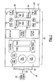
- Figures 1 and 2 are representative diagrams of an integrated skid system 100 to illustrate the broad concept of the invention.
- the example shown in Figures 1 and 2 is meant for illustrative purposes and is not meant to be limiting in any way.
- Those of ordinary skill in the art will understand that any number and type of system components and configurations can be used without departing from the scope of the invention.
- the integrated skid system 100 shown in Figure 1 integrates devices 101 having disparate functions onto a single skid 102 or other platform and controls these devices 101 via a single multi-motor controller 104 associated with the system 100.
- two motors 106 and their associated devices 101 e.g., oil pumps 108, oil valves 110, filters 112, etc.
- two motors 106 and their associated devices 101 are disposed on the same skid 102 even though they carry out different functions.
- the multi-motor controller 104 monitors and controls the devices 101 on the skid system 100, making it possible to control operation of a given device based on the operating states of other devices 101 on the same skid 102.
- devices 101 can be shared among separate engines, minimizing the total number of devices 101 needed to support the engines without sacrificing redundancy and fault-tolerance.
- a given engine may require four motors and their associated pump components: one primary motor and one backup motor for each engine.
- two engines would normally require a total of four motor and associated pump components because the motors are isolated from each other and controlled independently. Integrating the components allows the total number of motors for the two engines to be reduced to three: one primary motor for each engine and a backup motor shared between the two engines, to be used on whichever engine is experiencing a motor problem.
- the multi-motor controller 104 receives sensor data from multiple engines and devices 101 and makes decisions based on the received data, it can detect which engine is having the problem and switch the backup motor to either engine. Similar device sharing can be implemented for other devices 101, such as water and fuel pumps, in the system 100.
- the intelligent capability provided by the multi-motor controller 104 allows control over device operation to enable sharing of devices 101 among engines.
- the multi-motor controller 104 communicates with a system controller 120 via a simple connector 122, such as a serial or Ethernet-type connection.
- a simple connector 122 such as a serial or Ethernet-type connection.
- the decision-making functions regarding how to control a device are conducted by the multi-motor controller 104, while the actual plant control is conducted by the system controller 120.
- the system controller 120 can be kept very simple. Separating the plant control functions from the intelligent functions also allows a single system controller 120 to control devices 101 associated with a plurality of multi-motor controllers 104 with a minimal increase in the number of connections in the overall system, on the order of the number of additional integrated skids 100 rather than the number of additional devices 101.
- the multi-motor controller 104 itself has the intelligence and the power needed to control the various devices 101, such as the motors, in the skid system 100.
- the devices 101 in the skid system 100 have sensors that feed sensor data to the multi-motor controller 104 for the controller 104 to analyze.
- the multi-motor controller 104 may then, if needed, instruct the system controller 120 to actually control the devices 101 based on the analysis it conducted.
- the multi-motor controller 104 can conduct fault-tolerance and correction if the sensor data obtained from the devices 101 indicates the presence of a potential problem.
- the intelligent control provided by the multi-motor controller 104 is particularly useful in minimizing the number of devices needed to control critical functions.
- conventional turbine engine systems include both two AC motors and a backup DC motor to ensure that oil continues to be pumped to the generator by the DC motor in the case of an AC power failure, preventing the generator bearings from being damaged.
- Current system controllers 120 simply turn on the DC motor in reaction to the power failure.
- the multi-motor controller 104 in the inventive system makes it possible to use a motor that can run from both an AC source and a DC source so that the motor can be simply switched to operate from the DC source in case the multi-motor controller 104 detects an AC power failure.
- the intelligent control provided by the multi-motor controller 104 allows all of the DC pumps and motors to be eliminated completely from the system 100, greatly reducing the total hardware in the system 100.
- the multi-motor controller 104 makes other hardware reductions possible within the scope of the invention.
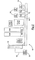
- Figure 3 illustrates an example of one particular embodiment of the multi-motor controller 104 that may be used in the inventive system 100.
- the controller 104 is not limited to the illustrated configuration, and other configurations may be used without departing from the scope of the invention.
- the multi-motor controller 104 is a modular controller that allows boards to be inserted and removed based on the specific devices 101 on the skid 100.
- a channel rack 200 has edge connectors 204 that can accommodate various plug-ins and controller cards to provide various functionalities to the controller 104.
- a housekeeping card 206 and a PCI I/O board 208 may be plugged into the channel rack 200.
- other boards such as a PC Ethernet card 210 or a standard PCI I/O data card 212, may also be connected to the channel rack 200 if desired.
- a main engine control I/O card 214 acts as an interface between the multi-motor controller 104 and the system controller 120.
- the multi-motor controller 104 can send instructions via main engine control I/O card 214 to the system controller 120 to, for example, turn devices on and off.
- the system controller 120 may also send information (e.g., requested engine speed, engine mode status, start, stop, synchronize, load shed, synchronous condensing, etc.) to the multi-motor controller 104 via the main engine control I/O card 214.
- Each of the devices 101 in the skid system 100 may have its own associated sensor 216 to provide information on the health and operating state of the device 101.
- the sensors 216 may collectively feed data into a connector I/O port 218 on the rack 200, providing the data needed for the controller 104 to decide how to control the devices.
- the particular sensor devices 216 that are needed in a given system 100 can vary depending on the specific devices on the skid.
- the input/output devices 216 may correspond to pressure and temperature flow transducers, current meters, DC meters, AC meters, etc., all of which can be plugged into the connector I/O port 218.
- This plug-in capability further illustrates the flexible, modular nature of the multi-motor controller 104 because any combination of devices 216 can be included in the system 100 without complicated modifications to the system 100 itself.
- Various miscellaneous control functions 220 may be included to control operation of devices that do not require intelligent control, such as constant speed motors, heaters, fans, relays, or other smaller devices that are either on or off (i.e., binary) rather than variable. This allows processing resources in the controller 104 to be reserved for variable control devices, such as variable speed motors.
- a local power supply module 222 may also be connected to the rack 200 to act as a switch to backup DC power supply that is tapped in case of an AC power failure.
- a given skid system 100 may have multiple motors 106 (e.g., an oil system motor, a water system motor, a fuel system motor, a ventilator motor, etc.).
- the embodiment shown in Figure 3 includes a digital signal processor (DSP) and gate driver interface card 224.
- DSP digital signal processor
- Each of these cards 224 is connected to the rack 200 by their own dedicated edge connectors 204 to link the rack 200 with a corresponding motor commutation module 226.
- the illustrated embodiment includes one DSP card 224 and motor commutation module 226 with each motor, some sharing among the cards 224 and modules 226 can be arranged among multiple motors if selected motors do not operate at the same time.
- a starter motor and a fuel motor would require separate cards 224 and modules 226 because they are used simultaneously when an engine is started.
- the starter motor and a motor that controls water injection into the motor can share a single card 224 and module 226 because water injection is not conducted during the engine start operation.
- a main system and a backup system may share the same card 224 and module 226 because the backup system will only operate if the main system fails.
- the DSP and gate driver interface cards 224 act as the motor controllers and the motor commutation modules 226 act as the switches that actually switch different legs of the motor to cause the motor to turn at a given speed.
- the DSP and gate driver interface cards 224 calculate the desired motor speed, current limits, and commutation pattern required to properly rotate the specific motor type being used (i.e., induction motor, permanent magnet motor, etc.).
- the DSP and gate driver interface cards 224 can be programmed to drive various types and size of motors, if desired.
- the motor commutation module 226 contains high power bus bars and high power switches, such as insulated gate bipolar transistors (IGBT) that actually switch the current on and off to the various phases of the motor being controlled.
- IGBT insulated gate bipolar transistors
- the invention provides improved system functionality with fewer devices in fluid handling systems. Rather than relying on the system controller alone, which simply turns the motors and associated devices on and off, the intelligent controller used in the invention is able to make decisions on when the motors will go on and off based on the operation of other motors and devices in the system. As a result, the inventive system provides redundancy and fault-tolerance via intelligent device control rather than through extra redundant devices. Moreover, moving devices having different functions onto a common skid reduces the overall plant footprint, making the system simpler and less costly to implement.
Landscapes
- Physics & Mathematics (AREA)
- General Physics & Mathematics (AREA)
- Engineering & Computer Science (AREA)
- Automation & Control Theory (AREA)
- Control Of Multiple Motors (AREA)
- Control Of Electric Motors In General (AREA)
Applications Claiming Priority (2)
| Application Number | Priority Date | Filing Date | Title |
|---|---|---|---|
| US816092 | 2004-04-01 | ||
| US10/816,092 US7733037B2 (en) | 2004-04-01 | 2004-04-01 | Integrated skid with multiple-motor controller |
Publications (2)
| Publication Number | Publication Date |
|---|---|
| EP1596263A1 true EP1596263A1 (de) | 2005-11-16 |
| EP1596263B1 EP1596263B1 (de) | 2008-08-13 |
Family
ID=34978815
Family Applications (1)
| Application Number | Title | Priority Date | Filing Date |
|---|---|---|---|
| EP05252009A Expired - Lifetime EP1596263B1 (de) | 2004-04-01 | 2005-03-31 | Integrierter Träger mit mehrmotorigem Regler |
Country Status (4)
| Country | Link |
|---|---|
| US (1) | US7733037B2 (de) |
| EP (1) | EP1596263B1 (de) |
| AT (1) | ATE404908T1 (de) |
| DE (1) | DE602005008812D1 (de) |
Cited By (1)
| Publication number | Priority date | Publication date | Assignee | Title |
|---|---|---|---|---|
| WO2011015198A1 (de) * | 2009-08-05 | 2011-02-10 | Man Diesel & Turbo Se | Mehrmotorenanlage und verfahren zum betreiben dieser |
Families Citing this family (8)
| Publication number | Priority date | Publication date | Assignee | Title |
|---|---|---|---|---|
| CN106227099A (zh) * | 2016-08-25 | 2016-12-14 | 西北工业大学 | 一种双绕组永磁同步电机的协同控制系统 |
| CN106301095B (zh) * | 2016-08-29 | 2019-06-28 | 江苏大学 | 一种多电机协调控制系统神经网络逆容错控制方法 |
| US10099796B2 (en) | 2016-10-04 | 2018-10-16 | General Electric Company | System and method for dynamically controlling the operation of an aircraft |
| US11137109B2 (en) * | 2019-04-19 | 2021-10-05 | Cactus Wellhead, LLC | Remote greasing system |
| CN113325814B (zh) * | 2021-06-09 | 2022-04-01 | 河北冀衡赛瑞化工有限公司 | 一种高塔硝基肥安全生产自动控制系统 |
| CN114603563A (zh) * | 2022-04-25 | 2022-06-10 | 国网湖南省电力有限公司 | 一种连续体机械臂的多丝杆电机总线型嵌入式控制系统 |
| US11899410B1 (en) | 2022-12-15 | 2024-02-13 | Halliburton Energy Services, Inc. | Monitoring a wellbore operation using distributed artificial intelligence |
| US11899438B1 (en) | 2022-12-15 | 2024-02-13 | Halliburton Energy Services, Inc. | Distributed control system with failover capabilities for physical well equipment |
Citations (5)
| Publication number | Priority date | Publication date | Assignee | Title |
|---|---|---|---|---|
| US5130616A (en) * | 1990-11-13 | 1992-07-14 | Southwest Electric Company | Motor control system and components thereof |
| US5670856A (en) * | 1994-11-07 | 1997-09-23 | Alliedsignal Inc. | Fault tolerant controller arrangement for electric motor driven apparatus |
| WO2001059288A2 (en) * | 2000-02-09 | 2001-08-16 | Parker Hannifin Corporation | Integrated pump unit |
| US20030200060A1 (en) * | 2002-04-22 | 2003-10-23 | Evren Eryurek | On-line rotating equipment monitoring device |
| US20030231875A1 (en) * | 2002-06-13 | 2003-12-18 | Halliburton Energy Services, Inc. | Digital adaptive sensorless commutational drive controller for a brushless dc motor |
Family Cites Families (11)
| Publication number | Priority date | Publication date | Assignee | Title |
|---|---|---|---|---|
| US5876370A (en) * | 1995-10-11 | 1999-03-02 | Sims Deltec, Inc. | Intermittent fluid delivery apparatus and method |
| IT1269440B (it) * | 1994-01-19 | 1997-04-01 | Fita Om Carrelli Elevatori S P | Carrello elevatore a motorizzazione elettrica |
| US5619111A (en) * | 1995-01-20 | 1997-04-08 | Kabushiki Kaisha Sankyo Seiki Seisakusho | Motor control system for controlling the operations of a plurality of servo motors |
| US6422018B1 (en) * | 2000-08-17 | 2002-07-23 | Lloyd B. Tisdale | Gas turbine engine modular cooling and heating apparatus |
| KR100371587B1 (ko) * | 2000-12-15 | 2003-02-11 | 한국과학기술연구원 | Can통신망을 이용한 유연한 소형의 전동기 제어장치 |
| US6825634B2 (en) * | 2001-01-18 | 2004-11-30 | Lockeed Martin Corporation | System and method for a scalable motion controller for controlling a plurality of servo motors |
| JP2002361838A (ja) * | 2001-06-13 | 2002-12-18 | Tokyo Kikai Seisakusho Ltd | 停電時制御が可能な輪転機の制御装置 |
| US6548977B2 (en) * | 2001-07-12 | 2003-04-15 | Seiberco Incorporated | Motor tracking control system |
| GB0117904D0 (en) * | 2001-07-23 | 2001-09-12 | Lucas Industries Ltd | Motor control system |
| US6812656B2 (en) * | 2002-02-27 | 2004-11-02 | Railpower Technologies Corp. | Sequenced pulse width modulation method and apparatus for controlling and powering a plurality of direct current motors |
| JP3719603B2 (ja) * | 2003-03-06 | 2005-11-24 | 多摩川精機株式会社 | 駆動回路内蔵型サーボモータの駆動方法 |
-
2004
- 2004-04-01 US US10/816,092 patent/US7733037B2/en not_active Expired - Fee Related
-
2005
- 2005-03-31 DE DE602005008812T patent/DE602005008812D1/de not_active Expired - Lifetime
- 2005-03-31 AT AT05252009T patent/ATE404908T1/de not_active IP Right Cessation
- 2005-03-31 EP EP05252009A patent/EP1596263B1/de not_active Expired - Lifetime
Patent Citations (5)
| Publication number | Priority date | Publication date | Assignee | Title |
|---|---|---|---|---|
| US5130616A (en) * | 1990-11-13 | 1992-07-14 | Southwest Electric Company | Motor control system and components thereof |
| US5670856A (en) * | 1994-11-07 | 1997-09-23 | Alliedsignal Inc. | Fault tolerant controller arrangement for electric motor driven apparatus |
| WO2001059288A2 (en) * | 2000-02-09 | 2001-08-16 | Parker Hannifin Corporation | Integrated pump unit |
| US20030200060A1 (en) * | 2002-04-22 | 2003-10-23 | Evren Eryurek | On-line rotating equipment monitoring device |
| US20030231875A1 (en) * | 2002-06-13 | 2003-12-18 | Halliburton Energy Services, Inc. | Digital adaptive sensorless commutational drive controller for a brushless dc motor |
Cited By (4)
| Publication number | Priority date | Publication date | Assignee | Title |
|---|---|---|---|---|
| WO2011015198A1 (de) * | 2009-08-05 | 2011-02-10 | Man Diesel & Turbo Se | Mehrmotorenanlage und verfahren zum betreiben dieser |
| CN102472190A (zh) * | 2009-08-05 | 2012-05-23 | 曼柴油机和涡轮机欧洲股份公司 | 多发动机设备及其工作方法 |
| JP2013501186A (ja) * | 2009-08-05 | 2013-01-10 | マン・ディーゼル・アンド・ターボ・エスイー | マルチエンジン設備および当該設備の動作方法 |
| CN102472190B (zh) * | 2009-08-05 | 2015-08-19 | 曼柴油机和涡轮机欧洲股份公司 | 多发动机设备及其工作方法 |
Also Published As
| Publication number | Publication date |
|---|---|
| DE602005008812D1 (de) | 2008-09-25 |
| US20050218841A1 (en) | 2005-10-06 |
| EP1596263B1 (de) | 2008-08-13 |
| US7733037B2 (en) | 2010-06-08 |
| ATE404908T1 (de) | 2008-08-15 |
Similar Documents
| Publication | Publication Date | Title |
|---|---|---|
| CN101368581B (zh) | 模块装置 | |
| EP2316160B1 (de) | Architektur paralleler motorsteuerungen | |
| CN102575679B (zh) | 潜水泵机组 | |
| US7733037B2 (en) | Integrated skid with multiple-motor controller | |
| US8881529B2 (en) | Modular fuel supply device for a gas turbine including a fuel supply device having an integrated control device | |
| CN113978480A (zh) | 一种冗余电子控制系统及设备 | |
| JP5286238B2 (ja) | 給水装置及び給水装置の制御方法 | |
| JPH11509387A (ja) | 複数の電気装置を制御するための制御システム | |
| JP7068458B2 (ja) | コンベアの制御装置 | |
| EP2657499B1 (de) | Flüssigkeitszuführvorrichtung | |
| CN102511124B (zh) | 致动器控制系统以及致动器系统 | |
| CN102769419B (zh) | 一种方便配置电机的集中式电机控制器 | |
| US6577095B1 (en) | Brushless alternating current electric servo motor drive | |
| FI124147B (fi) | Sähkökäyttöjärjestelmän vikadiagnostiikkajärjestely ja sähkökäyttöjärjestelmä | |
| CA2993384C (en) | VOLTAGE SUPPLY SYSTEM INTENDED FOR A SHIP OR POWER PLANT | |
| JPWO1997028370A1 (ja) | ターボ機械駆動装置及びその制御方法 | |
| PT2008162E (pt) | Grupo de bombas centrífugas com dispositivo de comutação | |
| KR102034534B1 (ko) | 물에서 가동되는 운송 수단을 위한 전기 모터 구동부의 냉각 | |
| JP2006009805A (ja) | ターボ機械駆動装置及びその制御方法 | |
| KR100844230B1 (ko) | 팬필터유닛 | |
| JP4381992B2 (ja) | 電子制御システムを備えるディーゼル・エンジン、特に大型ディーゼル・エンジン | |
| KR102816585B1 (ko) | 복수개의 모터들을 제어하기 위한 통합 전력 조절 시스템 및 방법 | |
| EP4518142A1 (de) | Elektrisches system für seilbahn oder stromerzeugungsanlage | |
| US6529032B1 (en) | Methods and apparatus for full I/O functionality and blocking of backdrive current | |
| US20250028668A1 (en) | Flexible backplane for system operations |
Legal Events
| Date | Code | Title | Description |
|---|---|---|---|
| PUAI | Public reference made under article 153(3) epc to a published international application that has entered the european phase |
Free format text: ORIGINAL CODE: 0009012 |
|
| AK | Designated contracting states |
Kind code of ref document: A1 Designated state(s): AT BE BG CH CY CZ DE DK EE ES FI FR GB GR HU IE IS IT LI LT LU MC NL PL PT RO SE SI SK TR |
|
| AX | Request for extension of the european patent |
Extension state: AL BA HR LV MK YU |
|
| 17P | Request for examination filed |
Effective date: 20060207 |
|
| AKX | Designation fees paid |
Designated state(s): AT BE BG CH CY CZ DE DK EE ES FI FR GB GR HU IE IS IT LI LT LU MC NL PL PT RO SE SI SK TR |
|
| GRAP | Despatch of communication of intention to grant a patent |
Free format text: ORIGINAL CODE: EPIDOSNIGR1 |
|
| GRAS | Grant fee paid |
Free format text: ORIGINAL CODE: EPIDOSNIGR3 |
|
| GRAA | (expected) grant |
Free format text: ORIGINAL CODE: 0009210 |
|
| AK | Designated contracting states |
Kind code of ref document: B1 Designated state(s): AT BE BG CH CY CZ DE DK EE ES FI FR GB GR HU IE IS IT LI LT LU MC NL PL PT RO SE SI SK TR |
|
| REG | Reference to a national code |
Ref country code: GB Ref legal event code: FG4D |
|
| REG | Reference to a national code |
Ref country code: CH Ref legal event code: EP |
|
| REG | Reference to a national code |
Ref country code: IE Ref legal event code: FG4D |
|
| REF | Corresponds to: |
Ref document number: 602005008812 Country of ref document: DE Date of ref document: 20080925 Kind code of ref document: P |
|
| PG25 | Lapsed in a contracting state [announced via postgrant information from national office to epo] |
Ref country code: NL Free format text: LAPSE BECAUSE OF FAILURE TO SUBMIT A TRANSLATION OF THE DESCRIPTION OR TO PAY THE FEE WITHIN THE PRESCRIBED TIME-LIMIT Effective date: 20080813 Ref country code: LT Free format text: LAPSE BECAUSE OF FAILURE TO SUBMIT A TRANSLATION OF THE DESCRIPTION OR TO PAY THE FEE WITHIN THE PRESCRIBED TIME-LIMIT Effective date: 20080813 Ref country code: IS Free format text: LAPSE BECAUSE OF FAILURE TO SUBMIT A TRANSLATION OF THE DESCRIPTION OR TO PAY THE FEE WITHIN THE PRESCRIBED TIME-LIMIT Effective date: 20081213 |
|
| PG25 | Lapsed in a contracting state [announced via postgrant information from national office to epo] |
Ref country code: AT Free format text: LAPSE BECAUSE OF FAILURE TO SUBMIT A TRANSLATION OF THE DESCRIPTION OR TO PAY THE FEE WITHIN THE PRESCRIBED TIME-LIMIT Effective date: 20080813 Ref country code: ES Free format text: LAPSE BECAUSE OF FAILURE TO SUBMIT A TRANSLATION OF THE DESCRIPTION OR TO PAY THE FEE WITHIN THE PRESCRIBED TIME-LIMIT Effective date: 20081124 Ref country code: SI Free format text: LAPSE BECAUSE OF FAILURE TO SUBMIT A TRANSLATION OF THE DESCRIPTION OR TO PAY THE FEE WITHIN THE PRESCRIBED TIME-LIMIT Effective date: 20080813 Ref country code: FI Free format text: LAPSE BECAUSE OF FAILURE TO SUBMIT A TRANSLATION OF THE DESCRIPTION OR TO PAY THE FEE WITHIN THE PRESCRIBED TIME-LIMIT Effective date: 20080813 |
|
| PG25 | Lapsed in a contracting state [announced via postgrant information from national office to epo] |
Ref country code: BE Free format text: LAPSE BECAUSE OF FAILURE TO SUBMIT A TRANSLATION OF THE DESCRIPTION OR TO PAY THE FEE WITHIN THE PRESCRIBED TIME-LIMIT Effective date: 20080813 |
|
| PG25 | Lapsed in a contracting state [announced via postgrant information from national office to epo] |
Ref country code: DK Free format text: LAPSE BECAUSE OF FAILURE TO SUBMIT A TRANSLATION OF THE DESCRIPTION OR TO PAY THE FEE WITHIN THE PRESCRIBED TIME-LIMIT Effective date: 20080813 Ref country code: BG Free format text: LAPSE BECAUSE OF FAILURE TO SUBMIT A TRANSLATION OF THE DESCRIPTION OR TO PAY THE FEE WITHIN THE PRESCRIBED TIME-LIMIT Effective date: 20081113 |
|
| PG25 | Lapsed in a contracting state [announced via postgrant information from national office to epo] |
Ref country code: RO Free format text: LAPSE BECAUSE OF FAILURE TO SUBMIT A TRANSLATION OF THE DESCRIPTION OR TO PAY THE FEE WITHIN THE PRESCRIBED TIME-LIMIT Effective date: 20080813 Ref country code: SK Free format text: LAPSE BECAUSE OF FAILURE TO SUBMIT A TRANSLATION OF THE DESCRIPTION OR TO PAY THE FEE WITHIN THE PRESCRIBED TIME-LIMIT Effective date: 20080813 Ref country code: CZ Free format text: LAPSE BECAUSE OF FAILURE TO SUBMIT A TRANSLATION OF THE DESCRIPTION OR TO PAY THE FEE WITHIN THE PRESCRIBED TIME-LIMIT Effective date: 20080813 Ref country code: PT Free format text: LAPSE BECAUSE OF FAILURE TO SUBMIT A TRANSLATION OF THE DESCRIPTION OR TO PAY THE FEE WITHIN THE PRESCRIBED TIME-LIMIT Effective date: 20090113 |
|
| PLBE | No opposition filed within time limit |
Free format text: ORIGINAL CODE: 0009261 |
|
| STAA | Information on the status of an ep patent application or granted ep patent |
Free format text: STATUS: NO OPPOSITION FILED WITHIN TIME LIMIT |
|
| 26N | No opposition filed |
Effective date: 20090514 |
|
| PG25 | Lapsed in a contracting state [announced via postgrant information from national office to epo] |
Ref country code: EE Free format text: LAPSE BECAUSE OF FAILURE TO SUBMIT A TRANSLATION OF THE DESCRIPTION OR TO PAY THE FEE WITHIN THE PRESCRIBED TIME-LIMIT Effective date: 20080813 |
|
| PG25 | Lapsed in a contracting state [announced via postgrant information from national office to epo] |
Ref country code: IT Free format text: LAPSE BECAUSE OF FAILURE TO SUBMIT A TRANSLATION OF THE DESCRIPTION OR TO PAY THE FEE WITHIN THE PRESCRIBED TIME-LIMIT Effective date: 20080813 |
|
| PG25 | Lapsed in a contracting state [announced via postgrant information from national office to epo] |
Ref country code: MC Free format text: LAPSE BECAUSE OF NON-PAYMENT OF DUE FEES Effective date: 20090331 |
|
| REG | Reference to a national code |
Ref country code: CH Ref legal event code: PL |
|
| REG | Reference to a national code |
Ref country code: FR Ref legal event code: ST Effective date: 20091130 |
|
| REG | Reference to a national code |
Ref country code: IE Ref legal event code: MM4A |
|
| PG25 | Lapsed in a contracting state [announced via postgrant information from national office to epo] |
Ref country code: SE Free format text: LAPSE BECAUSE OF FAILURE TO SUBMIT A TRANSLATION OF THE DESCRIPTION OR TO PAY THE FEE WITHIN THE PRESCRIBED TIME-LIMIT Effective date: 20081113 Ref country code: LI Free format text: LAPSE BECAUSE OF NON-PAYMENT OF DUE FEES Effective date: 20090331 Ref country code: IE Free format text: LAPSE BECAUSE OF NON-PAYMENT OF DUE FEES Effective date: 20090331 Ref country code: CH Free format text: LAPSE BECAUSE OF NON-PAYMENT OF DUE FEES Effective date: 20090331 |
|
| PG25 | Lapsed in a contracting state [announced via postgrant information from national office to epo] |
Ref country code: FR Free format text: LAPSE BECAUSE OF NON-PAYMENT OF DUE FEES Effective date: 20091123 |
|
| PG25 | Lapsed in a contracting state [announced via postgrant information from national office to epo] |
Ref country code: PL Free format text: LAPSE BECAUSE OF FAILURE TO SUBMIT A TRANSLATION OF THE DESCRIPTION OR TO PAY THE FEE WITHIN THE PRESCRIBED TIME-LIMIT Effective date: 20080813 |
|
| PG25 | Lapsed in a contracting state [announced via postgrant information from national office to epo] |
Ref country code: GR Free format text: LAPSE BECAUSE OF FAILURE TO SUBMIT A TRANSLATION OF THE DESCRIPTION OR TO PAY THE FEE WITHIN THE PRESCRIBED TIME-LIMIT Effective date: 20081114 |
|
| PG25 | Lapsed in a contracting state [announced via postgrant information from national office to epo] |
Ref country code: LU Free format text: LAPSE BECAUSE OF NON-PAYMENT OF DUE FEES Effective date: 20090331 |
|
| PG25 | Lapsed in a contracting state [announced via postgrant information from national office to epo] |
Ref country code: HU Free format text: LAPSE BECAUSE OF FAILURE TO SUBMIT A TRANSLATION OF THE DESCRIPTION OR TO PAY THE FEE WITHIN THE PRESCRIBED TIME-LIMIT Effective date: 20090214 |
|
| PG25 | Lapsed in a contracting state [announced via postgrant information from national office to epo] |
Ref country code: TR Free format text: LAPSE BECAUSE OF FAILURE TO SUBMIT A TRANSLATION OF THE DESCRIPTION OR TO PAY THE FEE WITHIN THE PRESCRIBED TIME-LIMIT Effective date: 20080813 |
|
| PG25 | Lapsed in a contracting state [announced via postgrant information from national office to epo] |
Ref country code: CY Free format text: LAPSE BECAUSE OF FAILURE TO SUBMIT A TRANSLATION OF THE DESCRIPTION OR TO PAY THE FEE WITHIN THE PRESCRIBED TIME-LIMIT Effective date: 20080813 |
|
| PGFP | Annual fee paid to national office [announced via postgrant information from national office to epo] |
Ref country code: DE Payment date: 20130327 Year of fee payment: 9 Ref country code: GB Payment date: 20130327 Year of fee payment: 9 |
|
| REG | Reference to a national code |
Ref country code: DE Ref legal event code: R119 Ref document number: 602005008812 Country of ref document: DE |
|
| GBPC | Gb: european patent ceased through non-payment of renewal fee |
Effective date: 20140331 |
|
| REG | Reference to a national code |
Ref country code: DE Ref legal event code: R119 Ref document number: 602005008812 Country of ref document: DE Effective date: 20141001 |
|
| PG25 | Lapsed in a contracting state [announced via postgrant information from national office to epo] |
Ref country code: GB Free format text: LAPSE BECAUSE OF NON-PAYMENT OF DUE FEES Effective date: 20140331 Ref country code: DE Free format text: LAPSE BECAUSE OF NON-PAYMENT OF DUE FEES Effective date: 20141001 |