EP1596381A2 - Optisches Informationsaufzeichnungsgerät - Google Patents
Optisches Informationsaufzeichnungsgerät Download PDFInfo
- Publication number
- EP1596381A2 EP1596381A2 EP05252862A EP05252862A EP1596381A2 EP 1596381 A2 EP1596381 A2 EP 1596381A2 EP 05252862 A EP05252862 A EP 05252862A EP 05252862 A EP05252862 A EP 05252862A EP 1596381 A2 EP1596381 A2 EP 1596381A2
- Authority
- EP
- European Patent Office
- Prior art keywords
- length
- pit
- pattern
- recording
- deviation
- Prior art date
- Legal status (The legal status is an assumption and is not a legal conclusion. Google has not performed a legal analysis and makes no representation as to the accuracy of the status listed.)
- Withdrawn
Links
Images








Classifications
-
- G—PHYSICS
- G11—INFORMATION STORAGE
- G11B—INFORMATION STORAGE BASED ON RELATIVE MOVEMENT BETWEEN RECORD CARRIER AND TRANSDUCER
- G11B7/00—Recording or reproducing by optical means, e.g. recording using a thermal beam of optical radiation by modifying optical properties or the physical structure, reproducing using an optical beam at lower power by sensing optical properties; Record carriers therefor
- G11B7/004—Recording, reproducing or erasing methods; Read, write or erase circuits therefor
- G11B7/0045—Recording
-
- G—PHYSICS
- G11—INFORMATION STORAGE
- G11B—INFORMATION STORAGE BASED ON RELATIVE MOVEMENT BETWEEN RECORD CARRIER AND TRANSDUCER
- G11B7/00—Recording or reproducing by optical means, e.g. recording using a thermal beam of optical radiation by modifying optical properties or the physical structure, reproducing using an optical beam at lower power by sensing optical properties; Record carriers therefor
- G11B7/004—Recording, reproducing or erasing methods; Read, write or erase circuits therefor
- G11B7/0045—Recording
- G11B7/00458—Verification, i.e. checking data during or after recording
-
- G—PHYSICS
- G11—INFORMATION STORAGE
- G11B—INFORMATION STORAGE BASED ON RELATIVE MOVEMENT BETWEEN RECORD CARRIER AND TRANSDUCER
- G11B7/00—Recording or reproducing by optical means, e.g. recording using a thermal beam of optical radiation by modifying optical properties or the physical structure, reproducing using an optical beam at lower power by sensing optical properties; Record carriers therefor
- G11B7/004—Recording, reproducing or erasing methods; Read, write or erase circuits therefor
-
- G—PHYSICS
- G11—INFORMATION STORAGE
- G11B—INFORMATION STORAGE BASED ON RELATIVE MOVEMENT BETWEEN RECORD CARRIER AND TRANSDUCER
- G11B7/00—Recording or reproducing by optical means, e.g. recording using a thermal beam of optical radiation by modifying optical properties or the physical structure, reproducing using an optical beam at lower power by sensing optical properties; Record carriers therefor
- G11B7/004—Recording, reproducing or erasing methods; Read, write or erase circuits therefor
- G11B7/0045—Recording
- G11B7/00456—Recording strategies, e.g. pulse sequences
-
- G—PHYSICS
- G11—INFORMATION STORAGE
- G11B—INFORMATION STORAGE BASED ON RELATIVE MOVEMENT BETWEEN RECORD CARRIER AND TRANSDUCER
- G11B7/00—Recording or reproducing by optical means, e.g. recording using a thermal beam of optical radiation by modifying optical properties or the physical structure, reproducing using an optical beam at lower power by sensing optical properties; Record carriers therefor
- G11B7/12—Heads, e.g. forming of the optical beam spot or modulation of the optical beam
- G11B7/125—Optical beam sources therefor, e.g. laser control circuitry specially adapted for optical storage devices; Modulators, e.g. means for controlling the size or intensity of optical spots or optical traces
- G11B7/126—Circuits, methods or arrangements for laser control or stabilisation
- G11B7/1267—Power calibration
Definitions
- the present invention relates to an optical information recording device, and more particularly, to an optical information recording device, which is effective in correcting phase deviation or length deviation of recording pits.
- Recording information on an optical information record medium such as an optical disk is carried out in such a manner that record data are modulated in accordance with the EFM (Eight to Fourteen Modulation) mode, a recording pulse is formed according to the modulation signal, and recording pits are then formed on the optical disk through control of the intensity or irradiation timing of laser light based on the recording pulse.
- EFM Eight to Fourteen Modulation
- the recording pits are formed using heat generated by irradiation of laser light, it is required that the recording pulse be set by taking the effects of thermal storage, thermal interference, etc. into consideration. Accordingly, in the prior art, the setting of various parameters constituting the recording pulse is defined in plural in the form called strategy depending upon the type of an optical disk, an optimal strategy that is best suitable for corresponding record environment is selected from the strategies, and is executed in a strategy circuit installed in the optical information recording device.
- the strategy executed by the strategy circuit is dependent upon the type of a manufacture and the record speed of an optical disk used for record reproduction, as well as individual device difference between optical information recording devices, deviation in the spot diameter of pick-up, deviation in equipment exactness, and the like. Therefore setting the optimal strategy is to improve recording quality.
- optimal record can be performed only on an optical disk of a maker type that has been previously stored in the memory. It is, however, impossible to perform optimal record on an optical disk of a maker type that has not been stored in the memory. Furthermore, although an optical disk is an optical disk of a maker type that has been previously stored in the memory, optimal record cannot be performed if the optical disk has a different record speed.
- the parameters for setting the strategy can include:
- Paragraph 0020 of this Patent Document reads ' ⁇ phase error with a channel clock is detected on a record pattern basis.
- the record compensation parameter controller 12 serves to optimize the emission waveform rule based on detection results in the phase error detection part 11. ⁇ '.
- This patent discloses techniques in which phase error is detected and corrected through comparison with the channel clock.
- Paragraph 0024 of the above Patent Document reads 'Thereafter, a test pattern for deciding the emission waveform rule is recorded. An area in which the test pattern is recoded is thus reproduced in order to examine the relation between a predetermined emission waveform rule and the amount of phase error.
- the amount of phase error is measured in each combination of the length of various marks and the length of various spaces immediately before the marks.
- a desired emission waveform rule is determined by estimating the emission waveform rule in which the amount of phase error becomes zero based on the measured amount of phase error.
- ⁇ ' discloses techniques in which the amount of phase error in each combination of the marks and the spaces is measured, and an emission waveform rule in which the amount of phase error becomes zero is estimated (see Figs. 8 and 12).
- the present invention provides techniques, which are effective in detecting deviation between a recording pit and a strategy in consideration of the setting of various parameters.
- an optical information recording device for recording information on an optical recordable medium through pulse irradiation of laser light, including means that performs test record on the optical recordable medium using a predetermined strategy, compares with a first reproduction pattern and a second reproduction pattern, which are obtained by reproducing the test record result, and detects deviation between the strategy and a record pattern formed by the test record.
- the strategy is one in which a pulse condition of laser light, which is set to obtain a desired pit shape, is defined.
- a specific pulse shape is provided in consideration of the length of a pit becoming an object of record, the relation with the length of a land immediately before, the relation with the length of a subsequent land, the influence of thermal storage or thermal interference, and so on, with respect to variation in irradiation power or a pulse width of laser light.
- Test record is performed in order to confirm difference in the case where record is actually carried out by using the strategy, and is executed using a test record area installed in a medium.
- the test record is carried out using a specific pattern, which is capable of detecting deviation between the strategy and an actual state of record in an effective manner. It is thus possible to obtain reproduction patterns corresponding to the record patterns comprised of a plurality of recording pits formed by such test record, by reproducing the record pattern.
- the reproduction pattern obtained through the reproduction of the test record result is various in type. Therefore, a variety of deviation, such as phase deviation or length deviation, can be detected by extracting and comparing two or more of the reproduction patterns, which are effective in detecting deviation between the strategy and the actual state of record.
- the two reproduction patterns are configured by a signal in which deviation between the strategy and the actual state of record is reflected. It is thus possible to detect the relative amount of deviation based on one pattern by comparing the reproduction patterns.
- the two reproduction patterns preferably have portions that are the same in a pit length or a land length, and different portions formed therebetween.
- the present invention is not limited to techniques in which two reproduction patterns are compared, but can be applied to techniques in which a plurality of reproduction patterns are compared, e.g., techniques in which a reference pattern and other patterns are compared using one reproduction pattern as the reference pattern.
- an optical information recording device for recording information on an optical recordable medium through pulse irradiation of laser light, including means that performs test record on the optical recordable medium using a plurality of recording pulses including a record pattern in which a fixed length pit, a fixed length land and a variable-length pit are consecutive and the length of the variable-length pit is different, means that reproduces the result of the test record to obtain a plurality of reproduction patterns respectively corresponding to the recording pulses, means that sets at least one of the reproduction patterns as a reference pattern, and sets at least one pattern other than the reference pattern as a comparison pattern, means that compares a signal of a portion corresponding to a fixed length land included in the reference pattern and a signal of a portion corresponding to a fixed length land included in the comparison pattern, and means that detects the amount of front phase deviation of a pit corresponding to the length of the variable-length pit included in the comparison pattern based on the comparison result.
- the length of the fixed length land which has to be constant in an ideal state of record, varies due to the influence of a front phase of the variable-length pit. It is thus possible to detect front phase deviation of the variable-length pit in an independent manner by detecting variation in the length. It is also preferred that all the lengths used for record are tested by sequentially changing the variable-length pits like 3T, 4T, ⁇ , 14T.
- an optical information recording device for recording information on an optical recordable medium through pulse irradiation of laser light, including means that performs test record on the optical recordable medium using a plurality of recording pulses including a record pattern in which a variable-length pit, a fixed length land and a fixed length pit are consecutive and the length of the variable-length pit is different, means that reproduces the result of the test record to obtain a plurality of reproduction patterns respectively corresponding to the recording pulses, means that sets at least one of the reproduction patterns as a reference pattern, and sets at least one pattern other than the reference pattern as a comparison pattern, means that compares a signal of a portion corresponding to a fixed length land included in the reference pattern and a signal of a portion corresponding to a fixed length land included in the comparison pattern, and means that detects the amount of rear end phase deviation of a pit corresponding to the length of the variable-length pit included in the comparison pattern based on the comparison result.
- the length of the fixed length land which has to be constant in an ideal state of record, varies due to the influence of a rear phase of the variable-length pit. It is thus possible to detect rear phase deviation of the variable-length pit in an independent manner by detecting variation in the length. It is also preferred that all the lengths used for record are tested by sequentially changing the variable-length pit like 3T, 4T, ⁇ , 14T.
- an optical information recording device for recording information on an optical recordable medium through pulse irradiation of laser light, including means that performs test record on the optical recordable medium using a plurality of recording pulses including a record pattern in which a variable-length land, a fixed length pit and a fixed length land are consecutive and the length of the variable-length land is different, means that reproduces the result of the test record to obtain a plurality of reproduction patterns respectively corresponding to the recording pulses, means that sets at least one of the reproduction patterns as a reference pattern, and sets at least one pattern other than the reference pattern as a comparison pattern, means that compares a signal of a portion corresponding to a fixed length pit included in the reference pattern and a signal of a portion corresponding to a fixed length pit included in the comparison pattern, and means that detects the amount of length deviation of a pit corresponding to the length of the variable-length land included in the comparison pattern based on the comparison result.
- the length of the fixed length pit which has to be constant in an ideal state of record varies due to the influence of thermal interference generating when a pit prior to the variable-length land is formed. It is thus possible to independently detect length deviation due to the influence of thermal interference of the fixed length pit by detecting variation in the length. It is also preferred that all the lengths used for record are tested by sequentially changing the variable-length land like 3T, 4T, ⁇ , 14T.
- an optical information recording device for recording information on an optical recordable medium through pulse irradiation of laser light, including means that performs test record on the optical recordable medium using a plurality of recording pulses including a record pattern in which a variable-length land, a fixed length pit and a fixed length land are consecutive and the length of the variable-length land is different, means that reproduces the result of the test record to obtain a plurality of reproduction patterns respectively corresponding to the recording pulses, means that compares a signal of a portion corresponding to a fixed length pit included in each of the reproduction patterns and a prescribed length of a pit corresponding to the length of the fixed length pit, and means that detects the amount of length deviation of a pit corresponding to the length of the fixed length pit based on the comparison result.
- length deviation can be detected in an independent way based on thermal interference of the fixed length pit.
- an optical information recording device for recording information on an optical recordable medium through pulse irradiation of laser light, including means that performs test record on the optical recordable medium using a plurality of recording pulses including a record pattern in which a variable-length land, a variable-length pit and a fixed length land are consecutive and the length of the variable-length pit is different, means that reproduces the result of the test record to obtain a plurality of reproduction patterns respectively corresponding to the recording pulses, means that compares a signal of a portion corresponding to a variable-length pit included in each of the reproduction patterns and a prescribed length of a pit corresponding to the length of the variable-length pit, and means that detects the amount of length deviation of a pit corresponding to the length of the variable-length pit based on the comparison result.
- variable-length pit and the fixed length land are consecutive, the length of the variable-length pit which must be identical to a prescribed length in an ideal state of record is changed due to the influence of lands before and behind and pits adjacent to the lands. It is thus possible to independently detect length deviation due to pit balance of the variable-length pit by detecting variation in the length. It is also preferred that all the lengths used for record are tested by sequentially changing the variable-length pit like 3T, 4T, ⁇ , 14T.
- an optical information recording device for recording information on an optical recordable medium through pulse irradiation of laser light, including means that performs test record on the optical recordable medium using a predetermined strategy, means that reproduces the result of the test record to obtain a binarization signal, means that counts the pulse length of the binarization signal using a predetermined clock signal, means that stores the count result in a predetermined storage area, means that writes a histogram of the count result, means that specifies the pit length and the land length included in the binarization signal using the histogram, means that searches first and second reproduction patterns from the record area based on the specified pit length and land length, and means that detects deviation between the strategy and a record pattern formed by the test record, by comparing the first and second reproduction patterns obtained through the search.
- the reproduction binarization signal obtained from the test record result is counted as a predetermined clock, and the count result is then stored. It is thus possible to perform a variety of statistical processing on the obtained reproduction patterns, or to extract specific patterns.
- the count of the reproduction binarization signal can be carried out using a counter that starts the count of the polarity reversing edge of the binarization signal. The length of a pit and the length of a land can be thus obtained as count data.
- the count data obtained thus are stored in a predetermined record area of a memory device, etc., which is installed in the record device, and are then accumulated to a certain amount.
- the accumulated count data are used to write a histogram in which the occurrence frequency of each count value is analyzed.
- the range of the count value and the length of the pit and land are associated through the histogram. This allows for the search and extraction of data strings including desired pit and land patterns from the vast amounts of the count data stored in the storage area.
- pattern groups in which 'a fixed length pit, a fixed length land and a variable-length pit' are consecutive are searched, extracted and compared.
- pattern groups in which 'a variable-length pit, a fixed length land and a fixed length pit' are consecutive are searched, extracted and compared.
- pattern groups in which 'a variable-length land, a fixed length pit and a fixed length land' are consecutive are searched, extracted and compared.
- pattern groups in which 'a fixed length land, a variable-length pit and a fixed length land' are consecutive are searched, extracted and compared.
- pattern groups in which 'a fixed length land, a variable-length pit and a fixed length land' are consecutive are searched, extracted and compared.
- the amount of deviation caused by various factors can be detected in the best suitable manner. It is also possible to execute data processing, such as the above histogram, using an operation element such as CPU installed in the record device.
- Detection of the pit length and the land length using the histogram can be carried out using distribution of the occurrence frequency as the determination reference. This allows for effective decision although deviation between a strategy and an actual record pattern is high.
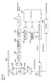
- Fig. 1 is a block diagram showing an internal construction of an optical information recording device according to the present invention. As shown in Fig. 1, the optical information recording/reproducing device is adapted to record and reproduce information on and from an optical disk 100 using laser light output from a laser oscillator 103.
- a recording signal corresponding to desired record information is encoded by means of an encoder 101 in the EFM mode, and the encoded record data are provided to a strategy circuit 102.
- the strategy circuit 102 has various setting parameters of a predetermined strategy set therein.
- the strategy circuit 102 serves to correct various setting parameters of a strategy, and control the intensity of laser light output from the laser oscillator 103 or a pulse width, thus generating a recording pulse capable of obtaining a desired state of record.
- the recording pulse formed by the strategy circuit 102 is applied to the laser oscillator 103.
- the laser oscillator 103 controls output laser light according to the recording pulse, and irradiates the controlled laser light toward the optical disk 100, which rotates at a constant linear velocity or at a constant rotational speed, through a lens 104, a half mirror 105 and a lens 106.
- a record pattern consisting of strings of pits and lands corresponding to desired record data is thus recorded on the optical disk 100.
- constant reproduction laser light output from the laser oscillator 103 is irradiated toward the optical disk 100, which rotates at a constant linear velocity or at a constant rotational speed, through the lens 104, the half mirror 105 and the lens 106.
- the reproduction laser light has the intensity weaker than the laser light output from the laser oscillator 103 upon record.
- Reflected light of the reproduction laser light from the optical disk 100 is received by an optical receiving unit 108 through the lens 106, the half mirror 105 and a lens 107, and is then converted into the electric signal.
- An electric signal output from the optical receiving unit 108 corresponds to the record pattern composed of pits and lands, which is recorded on the optical disk 100.
- the electric signal output from the optical receiving unit 108 undergoes a predetermined compensation process in a reproduction compensation circuit 109, and is then binarized by means of a binarization circuit 110.
- the signal is then decoded by a decoder 111, and is then output as a reproduction signal.
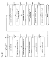
- Fig. 2 is a flowchart illustrating the execution sequence of the strategy decision process that is executed by the optical information recording device shown in Fig. 1.
- the optical information recording device shown in Fig. 1 first performs test record on the optical disk 100 in accordance to a plurality of record patterns in which various parameters of a strategy are changed in order to set the various parameters of the record strategy executed by the strategy circuit 102 (step S10).
- a record deviation detection unit 112 then counts the reproduction binarization signals obtained from the binarization circuit 110 by a counter in synchronization with a predetermined clock (step S14), and then stores the lengths of the pits and lands included in the reproduction binarization signals in a record area 115 as count data (step S16).
- the record deviation detection unit 112 then writes a histogram showing the occurrence frequency every count value using the count data accumulated on the record area 115 (step S18), and decides a threshold of the count result, which becomes the decision reference of a pit length and a land length, based on the histogram (step S20).
- the record deviation detection unit 112 searches plural kinds of specific patterns including specific pit/land patterns from the count data stored in the record area 115 on the basis of the threshold (step S22). It then finds an average length of each of the pits and the lands constituting the specific patterns by calculating an average of the count result having the same pit length included in the specific pattern and the count result having the same land length (step S24).
- the record deviation detection unit 112 sets one of the plurality of the extracted specific patterns as the reference pattern, and then compares the reference pattern with other patterns (step S26) to detect the following amounts of deviation, respectively, in an independent way (step S28).
- an operational expression deriving unit 113 derives an operational expression for deciding an optimal strategy based on the amount of deviation, which is detected by the record deviation detection unit 112.
- a strategy decision unit 114 estimates the control result of various parameters in accordance with the operational expression derived by the operational expression deriving unit 113 (step S30), decides a strategy correction value for adjusting a power or a pulse width of the laser light based on the estimated result, and sets the corrected optimal strategy in the strategy circuit 102 (step S32).
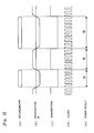
- Fig. 3 is a conceptual view showing the operational concept from the test record shown in Fig. 2 to the count of the reproduction data.
- recording pits as shown in Fig. 3A are formed on the optical disk.
- a reproduction RF signal corresponding to the recording pits can be obtained, as shown in Fig. 3B.
- a reproduction binarization signal as shown in Fig. 3C can be obtained.
- the pulse length between polarity reversions of the binarization signal is counted using a clock signal as shown in Fig. 3D, the count result as shown in Fig. 3E can be obtained.
- Fig. 4 is a conceptual view showing a storage image of the count result shown in Fig. 3.
- the count results of the binarization signal counted using the clock signal are sequentially stored in a table installed in the storage area 115 in a time-series manner, while the pits and the lands are discriminated with a polarity reversing part serving as a break.
- the table shown in Fig. 4 is stored in a state that an address searchable afterwards is attached thereto.
- Fig. 5 is a conceptual view showing the image of the written histogram shown in Fig. 2.
- a histogram can be obtained in the case where the occurrence frequency of count values is graphed.
- the histogram is written with pits and lands being separated, two kinds of the histograms; a pit histogram showing the count tendency of pits shown in Fig. 5A, and a land histogram showing the count tendency of lands shown in Fig. 5B can be obtained.
- Fig. 6 is a conceptual view showing the image of threshold decision shown in Fig. 2.
- a pit length threshold that becomes the decision reference of the pit length and a land length threshold that becomes the decision reference of the land length are set in the pit histogram and the land histogram, respectively.
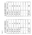
- Fig. 7 is a conceptual view showing an example of a threshold that is obtained by the scheme shown in Fig. 6.
- the pit length threshold is defined at each border of each pit length, as shown in Fig. 7A
- the land length threshold is defined at each border of each land length, as shown in Fig. 7B.
- a threshold becoming the border of 3T and 4T 9'.
- the thresholds are set until the border of 14T and 15T.
- a threshold becoming the border of 3T and 4T 9'.
- step S22 The details of each of the processes from the process of searching a specific pattern as shown in Fig. 2 (step S22) to the process of detecting the amount of deviation (step S28) will be below described. Those processes are carried out based on the detection principle of various deviations in the record deviation detection unit 112.
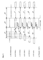
- Fig. 8 is a conceptual view showing an example of a record pattern and a reproduction pattern for detecting the amount of front phase deviation in each pit length.
- test record is performed using a recording pulse shown in Fig. 8A.
- the recording pulse is one in which the pit length of the variable pit PzT is changed as 3T, 4T, ⁇ , 7T, as shown in Figs. 8B to F with the pit length of a fixed pit PxT and the land length of a fixed land LyT being fixed, as well as a pattern in which the fixed pit PxT, a fixed land LyT and a variable pit PzT are continuous is included.
- change in the length of a variable pit is carried out until 14T.
- the measured length will be constant in an ideal state of record.
- the amount of deviation in the ideally prescribed length of the fixed land LyT length corresponds to the amount of front phase deviation for the recording pulse of pits P3T, P4T, ⁇ , P14T of each of 3T, 4T, ⁇ , 14T in the strategy upon record since the pit length of the pit PxT is fixed.
- the pattern of Fig. 8B in which the variable pit PzT becomes 3T is set as the reference pattern, and the remaining patterns from Figs. 8C to 8F are set as comparison patterns.
- the amount of front phase deviation FPS4T to FPS7T with respect to the reference pattern can be obtained, as shown in Figs. 8C to 8F.
- the amount of deviation FPS3T to FPS7T can be detected as relative values based on a given portion.
- the amount of front phase deviation FPS3T being the reference pattern can be defined as zero, or it can be detected as the amount of deviation from an ideal length.
- any one of the patterns shown in Figs. 8C to 8F can be set as the reference pattern instead of the pattern shown in Fig. 8B.
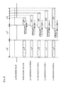
- Fig. 9 is a conceptual view showing an example of a record pattern and a reproduction pattern for detecting the amount of rear phase deviation in each pit length.
- test record is performed using a recording pulse shown in Fig. 9A.
- the recording pulse is one in which the pit length of the variable pit PxT is changed as 3T, 4T, ⁇ , 7T, as shown in Figs. 9B to 9F with the land length of a fixed land LyT and the pit length of a fixed pit PzT being fixed, as well as a pattern in which the variable pit PxT, the fixed land LyT and the fixed pit PzT are consecutive is included.
- change in the length of the variable pit can be carried out until 14T.
- the measured length in the case where the length of the fixed land LyT of the record pattern is measured, the measured length will be constant in an ideal state of record. If the length of the fixed land LyT is too deviated from an ideally prescribed length, the amount of deviation in the ideally prescribed length of the fixed land LyT length corresponds to the amount of rear phase deviation for the recording pulse of pits P3T, P4T, ⁇ , P14T of each of 3T, 4T, ⁇ , 14T in the strategy upon record since the pit length of the pit PzT is fixed.
- the pattern of Fig. 9B in which the variable pit PxT becomes 3T is set as a reference pattern, and the remaining patterns of Figs. 9C to 9F are set as comparison patterns.
- the amounts of rear phase deviation RPS4T to RPS7T with respect to the reference pattern can be obtained, as shown in Figs. 9C to 9F.
- the amount of rear phase deviation of the reference pattern RPS3T can be defined as zero, or it can be detected as the amount of deviation from an ideal length.
- any one of the patterns shown in Figs. 9C to 9F can be set as the reference pattern instead of the pattern shown in Fig. 9B.
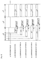
- Fig. 10 is a view illustrating an example of a record pattern for detecting the amount of pit deviation due to thermal interference.
- test record is performed using a recording pulse shown in Fig. 10A.
- the recording pulse is one in which the land length of a variable land LxT is changed as 3T, 4T, ⁇ , 7T, as shown in Figs. 10B to 10F with the pit length of a fixed pit PyT and the land length of a fixed land LzT being fixed, as well as a pattern in which the land LxT, the pit PyT and the land LzT are consecutive is included.
- change in the length of the variable land can be performed until 14T.
- the measured length in the case where the length of the fixed pit PyT of the record pattern is measured, the measured length will be constant in an ideal state of record.
- the amount of deviation in the ideally prescribed length of the fixed pit PyT corresponds to the amount of deviation due to thermal interference of a pit formed immediately before the variable land LxT because the land length of the land LzT is fixed.
- the pattern of Fig. 10B in which the variable land LxT becomes 3T is set as a reference pattern, and the remaining patterns of Figs. 10C to 10F are set as comparison patterns.
- the amounts of front phase deviation HID3T to HID7T with respect to the reference pattern can be obtained, as shown in Figs. 10C to 10F.
- the amount of front phase deviation of the reference pattern HID3T can be defined as zero, or it can be detected as the amount of deviation from an ideal length.
- any one of the patterns shown in Figs. 10C to 10F can be set as the reference pattern instead of the pattern shown in Fig. 10B.
- Fig. 11 is a view illustrating an example of detecting the amount of pit deviation due to thermal interference through comparison with a standard length. Referring to Figs. 11B to 11G, the amounts of front phase deviation HID3T to HID7T can be found by comparing the fixed pit PyT of each pattern with the standard length without setting the reference pattern as in Fig. 10.
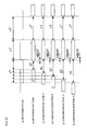
- Fig. 12 is a view illustrating an example of a record pattern for detecting the amount of deviation by pit balance.
- test record is performed using a recording pulse shown in Fig. 12A.
- the recording pulse is one in which the pit length of a variable pit PxT is changed as 3T, 4T, ⁇ , 7T, as shown in Figs. 12B to 12F with the land length of a fixed land LyT and the land length of a fixed land LzT being fixed, as well as a pattern in which a land LxT, a pit PyT and a land LzT are consecutive is included.
- change in the length of the variable land is carried out until 14T.
- the measured length will correspond to each ideal pit length in an ideal state of record.
- the amount of deviation from a prescribed length of the pit PyT of the variable length corresponds to the amount of length deviation for a recording pulse of pits P3T, P4T, ⁇ , P14T of each of 3T, 4T, ⁇ , 14T in a strategy upon record because the land length of the land LxT and the land length of the land LzT are fixed.
- the amount of deviation from the ideal length of each pit length is detected through comparison of the record result of the pit PyT of the variable length and the standard length of each pit, as shown in Figs. 12B to 12F by performing test record using any strategy, the amount of length deviation in each pit length can be detected from a reproduction pattern of the test record by the recording pulse.
- Fig. 13 is a conceptual view showing a table configuration for searching a specific pattern used for deviation detection in the phase before the pit and deviation detection in the phase after the pit.
- a data string that fulfills a threshold is extracted by searching data stored in the storage area 115 of Fig. 1 (corresponding to step S22 in Fig. 2) on the basis of the range of the threshold shown in Fig. 13A regarding the pit PxT, the land LyT and the pit PzT which are set on a specific pattern basis.
- Fig. 13B shows an example of the threshold in the case where detection of deviation in the phase after the pit is carried out. The spirit and operation of Fig. 13B are the same as those in the case where detection of deviation in the phase before the pit is carried out.
- Fig. 14 is a conceptual view showing a table configuration for searching a specific pattern used for pit interference deviation detection and pit balance deviation detection. As shown in Figs. 14A and 14B, detection of pit interference deviation and detection of pit balance deviation are also performed in the same manner as that of deviation in the phase before the pit and deviation in the phase after the pit, which have been described with reference to Figs. 13A and 13B.
- Fig. 15 is a conceptual view of a concrete example in which the amount of deviation is detected through relative comparison of count results.
- Fig. 15 there is shown an example in which deviation in the phase before the pit is detected. The amounts of deviation except for that can be also detected in the same manner.
- a reference pattern and a comparison pattern shown in Figs. 15A and B are first searched in and extracted from the data stored in the storage area, and count values for portions, which must have been originally a fixed length, are compared, as shown in Figs. 15C and 15D.
- a land LyT becomes a portion of comparison
- a difference between '12' shown in Fig. 15C being the count result of the reference pattern and '11' shown in Fig. 15D being the count result of the comparison pattern is found, and the found difference '1' becomes the value of the amount of deviation FPS4T.
- Fig. 16 is a conceptual view of a concrete example in which the amount of deviation is detected through absolute comparison of count results.
- a specific pattern shown in Fig. 16A is first searched in and extracted from data groups stored in the storage area, and count values of both for a portion that becomes an object of comparison are compared, as shown in Figs. 16B and 16C.
- a pit 3T is the portion of comparison
- a difference between '9' shown in Fig. 16B being count result of a specific pattern and '8' shown in Fig. 16C being the count result corresponding to the standard length are found, and the obtained difference '1' becomes a value of the amount of deviation of the pit 3T.
- Fig. 17 is a flowchart illustrating an example of performing estimation of the amount of control shown in Fig. 2.
- the process of estimating the amount of control can be performed by executing a series of processes of performing test record under two or more kinds of conditions, such as S1 and S2 having different record conditions, (step S100), reproducing the obtained recording pits (step S102), finding the amount of deviation D1 corresponding to the condition S1 and the amount of deviation D2 corresponding to the condition S2 through comparison of obtained reproduction patterns (step S104), performing linear approximation on the relation between the conditions S1 and S2 and the amount of deviation D1 and D2 (step S106), and deciding the amount of optimal correction based on the straight line (step S108).
- the amounts of the deviation D1 and D2 detected as such vary depending upon various setting parameters of a strategy. Further, it was found that the amounts of the deviation D1 and D2, which vary depending upon various setting parameters of a strategy, is changed almost in the linear shape as a result of analysis.
- the amount of deviation in each test record detected by the record deviation detection unit 112 can be considered as change in the linear shape, which is approximated according to a least-square method.
- an optimal strategy can be decided by aiming at the linear relation between various setting parameters of a strategy and the straight line of the amounts of the detected deviation D1 and D2.
- curve approximation can also be performed instead of the linear approximation.
- Fig. 18 is a conceptual view showing parameters that are changed by the record conditions S1 and S2 shown in Fig. 17.
- Fig. 18A shows an example in which a single pulse consisting of a single pulse pattern is employed.
- Fig. 18B shows an example in which a multi-pulse composed of a plurality of pulse patterns is employed.
- a single pulse 10-1 and a multi pulse 10-2 include a first pulse 12 disposed at the head of a pulse, and a rear end pulse 14 disposed at the rear end of the pulse, respectively.
- the amount of energy of the entire recording pulse is prescribed as the height of each pulse, the amount of energy at the head end, which is applied to the head of the recording pit, is defined as the length indicated by a first pulse width Ttop.
- the amount of energy applied to the rear end of the recording pit is prescribed as the length indicated by a rear end pulse width Tlast.
- a low power area which is lower by PWD than a main power PW, is formed between the first pulse 12 and the rear end pulse 14, as shown in Fig. 18A. If the amount is regulated, a recording pit is prevented from being astray. In the same manner, in case of the multi pulse 10-2, the width Tmp of an intermediate pulse disposed between the first pulse 12 and the rear end pulse 14 is regulated, as shown in Fig. 18B. Thus, a recording pit is prevented from being astray.
- Ttop, Tlast, PWD and Tmp become representative parameters that change the record conditions S1 and S2. These parameters are changed by means of the conditions S1, S2, and its influence are then detected by means of the amounts of the deviation D1 and D2. Linear approximation is performed using these four points, and the amount of correction capable of canceling deviation is obtained using a corresponding straight line.
- Fig. 19 is a conceptual view showing the relation between change in the record conditions S1, S2 and the amounts of deviation D1, D2.
- a reference pattern shown in Fig. 19A1 corresponding to the recording pulse of Fig. 19A is obtained
- a comparison pattern S1 shown in Fig. 19B1 corresponding to the recording pulse of Fig. 19B is obtained
- a comparison pattern S2 shown in Fig. 19C1 corresponding to the recording pulse of Fig. 19C is obtained.
- the comparison pattern S1 causes the amount of deviation of D1 to occur corresponding to the amount of control S1
- the comparison pattern S2 causes the amount of deviation of D2 to occur corresponding to the amount of control S2.
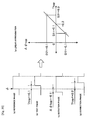
- Fig. 20 is a conceptual view showing an example of front phase deviation correction employing linear approximation.
- Ttop for front phase deviation when a pulse position becoming the reference is a reference phase ⁇ as shown in Fig. 20A, test record is performed using a waveform in which the pulse position is deviated by Ttop (corresponding to the record conditions S1, S2), as shown in Fig. 20B.
- phase deviation ⁇ top of the obtained reproduction signal is detected, as shown in Fig. 20C (corresponding to the amount of deviation D1, D2).
- the relation between change of a strategy S1, S2 and change in the amount of deviation D1, D2 can undergo linear approximation or curve approximation if at least two-change point is found. It is thus possible to obtain the amount of optimal correction, in which the amount of deviation becomes zero, using the straight line.
- the strategy S corresponding to the amount of ideal deviation D is found, and the strategy S is set in the strategy circuit 102 shown in Fig. 1, so that optimal correction of the recording pulse can be performed.
- the amount of deviation, which is detected from a reproduction pattern of test record using a strategy S1 is D1
- the amount of deviation, which is detected from a reproduction pattern of test record using a strategy S2 is D2
- the optimal strategy S is decided by substituting the output amount of deviation D for improving record fitness, e.g., for correcting initial output deviation, etc., which occurs in an equalizer, into the above function.
- the function for finding the optimal strategy S can be found corresponding to pits P3T, P4T, ⁇ , P14T of each of 3T, 4T, ⁇ , 14T.
- the function for finding the optimal strategy S can be found corresponding to the record speed.
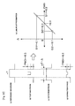
- Fig. 21 is a conceptual view showing an example of rear phase deviation correction employing linear approximation.
- Tlast for rear phase deviation is decided, when a pulse position becoming the reference is a reference phase ⁇ as shown in Fig. 21 A, test record is performed using a waveform in which the pulse position is deviated by Tlast, as shown in Fig. 21 B. As a result, phase deviation ⁇ last of an obtained reproduction signal is detected, as shown in Fig. 21 C.
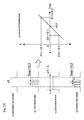
- Fig. 22 is a conceptual view showing an example of length deviation correction employing linear approximation regarding the shape of a single pulse.
- the amount of correction PWD for corresponding length deviation is decided, when a pulse length becoming the reference is a reference waveform nT as shown in Fig. 22A, test record is performed using a waveform in which the center of the pulse is obviated by PWD, as shown in Fig. 22B. Resultantly, length deviation ⁇ of an obtained reproduction signal can be detected, as shown in Fig. 22C.
- Fig. 23 is a conceptual view showing an example of length deviation correction employing linear approximation regarding the shape of multi pulses.
- the amount of correction Tmp for corresponding length deviation is decided, when a pulse length becoming the reference is a reference waveform nT as shown in Fig. 23A, test record is performed using a waveform in which an intermediate pulse length is Tmp as shown in Fig. 23B. As a result, length deviation ⁇ of an obtained reproduction signal is detected, as shown in Fig. 23C.
- Fig. 24 is a conceptual view showing a table structure for storing the amount of correction Ttop and Tlast.
- the amount of correction Ttop is defined with it being combined with the forward land length of each pit every pit length becoming an object of correction. For example, if a pit being the object of correction is 3T and the forward land of the pit is 3T, the amount of correction is stored in an area indicated by '3-3' in the drawing. If a pit being the object of correction is 4T and the forward land of the pit is 3T, the amount of correction is stored in an area indicated by '3-4' in the drawing. The same principle as that of 3T and 4T is applied to 5T, ⁇ , 14T.
- the amount of correction Tlast is defined with it being combined with the backward land length of each pit every pit length becoming the object of correction. For example, when a pit being the object of correction is 3T and the backward land of the pit is 3T, the amount of correction is stored in an area indicated by '3-3' in the drawing. If a pit being the object of correction is 4T and the backward land of the pit is 3T, the amount of correction is stored in an area indicated by '3-4' in the drawing. The same principle as that of 3T and 4T is applied to 5T, ⁇ , 14T.
- Fig. 25 is a conceptual view showing a table structure for storing the amount of correction PWD and Tmp.
- the amount of correction PWD and Tmp is defined every pit length becoming the object of correction.
- the amount of correction PWD when a pit being the object of correction is 3T is stored in an area indicated by 'PW3' in the drawing.
- the amount of correction Tmp when the pit being the object of correction is 3T is stored in an area indicated by 'Tm3' in the drawing.
- the same principle as that of 3T is applied to 4T, 5T, ⁇ , 14T.
- Fig. 26 is a conceptual view showing an example of a recording pulse after correction.
- a strategy to which an optimal correction value is applied is set on a pit-length basis. For example, in the event that 3T pit is recorded, a front correction value Ttop of 3T pit is read corresponding to the land length at a position former than the table shown in Fig. 24, as shown in Fig. 26B, and a rear correction value Tlast of 3T pit is read corresponding to the backward land length.
- Ttop and Tlast the front and rear ends of the recording pulse are corrected using corresponding Ttop and Tlast.
- Ttop and Tlast are corrected in the same sequence as that of 3T pit, as shown in Fig. 26C.
- a PWD correction value of a corresponding pit length is read from the table shown in Fig. 25 as well as Ttop and Tlast, as shown in Figs. 26D to 26F. Therefore, the pulse shape corresponding to the value of corresponding PWD is corrected.
- an optimal strategy S is decided by substituting the amount of deviation D into the function for finding the optimal strategy S. It is, however, to be understood that the optimal strategy S can be decided based on the correction table using the correction table obtained from the function.
- the process of setting the optimal strategy can be performed whenever the type of an optical disk is changed or the record speed varies.
- the condition of the optimal strategy, which is decided in the process of setting the optimal strategy is stored in a memory in such a way to correspond to the type of the optical disk and the record speed. In this state, in the case where record is again performed using the same kind of the optical disk or at the same record speed, the optimal strategy stored in the memory can be read and used.
Landscapes
- Physics & Mathematics (AREA)
- Optics & Photonics (AREA)
- Optical Recording Or Reproduction (AREA)
- Optical Head (AREA)
Applications Claiming Priority (2)
| Application Number | Priority Date | Filing Date | Title |
|---|---|---|---|
| JP2004143565 | 2004-05-13 | ||
| JP2004143565A JP4280996B2 (ja) | 2004-05-13 | 2004-05-13 | 光情報記録装置 |
Publications (2)
| Publication Number | Publication Date |
|---|---|
| EP1596381A2 true EP1596381A2 (de) | 2005-11-16 |
| EP1596381A3 EP1596381A3 (de) | 2008-08-13 |
Family
ID=34941225
Family Applications (1)
| Application Number | Title | Priority Date | Filing Date |
|---|---|---|---|
| EP05252862A Withdrawn EP1596381A3 (de) | 2004-05-13 | 2005-05-10 | Optisches Informationsaufzeichnungsgerät |
Country Status (6)
| Country | Link |
|---|---|
| US (1) | US20050265184A1 (de) |
| EP (1) | EP1596381A3 (de) |
| JP (1) | JP4280996B2 (de) |
| KR (1) | KR100656386B1 (de) |
| CN (1) | CN100447867C (de) |
| TW (1) | TWI356406B (de) |
Families Citing this family (9)
| Publication number | Priority date | Publication date | Assignee | Title |
|---|---|---|---|---|
| JP4395450B2 (ja) * | 2005-02-08 | 2010-01-06 | 太陽誘電株式会社 | 光情報記録装置および信号処理回路 |
| JP4422650B2 (ja) * | 2005-06-15 | 2010-02-24 | 三星電子株式会社 | 光情報記録装置およびパワー設定方法 |
| TWI328806B (en) * | 2005-06-17 | 2010-08-11 | Lite On It Corp | Method for adjusting write strategy of optical disc |
| KR20070065632A (ko) * | 2005-12-20 | 2007-06-25 | 삼성전자주식회사 | 기록 조건 최적화 방법 및 장치 및 광 기록 매체 |
| JP4564461B2 (ja) * | 2006-03-09 | 2010-10-20 | 太陽誘電株式会社 | 光情報記録再生装置、光情報記録処理方法、プログラム、及び中央演算装置 |
| JP2007317343A (ja) * | 2006-04-28 | 2007-12-06 | Sharp Corp | 記録パラメータ設定装置、そのプログラムおよび該プログラムを記録したコンピュータ読取り可能な記録媒体、情報記録媒体、ならびに記録パラメータ設定方法 |
| JP4597911B2 (ja) * | 2006-06-02 | 2010-12-15 | 太陽誘電株式会社 | 光記録再生方法および装置および信号処理回路および光記録再生プログラムおよび情報記録媒体 |
| JP4952152B2 (ja) * | 2006-09-06 | 2012-06-13 | 株式会社日立製作所 | パルス幅制御等化回路 |
| JP4691539B2 (ja) * | 2006-11-16 | 2011-06-01 | 太陽誘電株式会社 | 記録パワー補正方法及び光ディスク記録再生装置 |
Family Cites Families (13)
| Publication number | Priority date | Publication date | Assignee | Title |
|---|---|---|---|---|
| JP2702018B2 (ja) * | 1991-11-18 | 1998-01-21 | 太陽誘電株式会社 | 光情報記録方法及びその装置 |
| KR100188435B1 (ko) * | 1993-02-25 | 1999-06-01 | 윤종용 | 광자기 디스크장치의 트랙보상장치 |
| US5703855A (en) * | 1993-04-06 | 1997-12-30 | Hitachi, Ltd. | Optical disk apparatus and recording and reading method for an optical disk using the same |
| JP3437239B2 (ja) * | 1994-02-16 | 2003-08-18 | オリンパス光学工業株式会社 | 情報再生装置 |
| US5696756A (en) * | 1995-04-14 | 1997-12-09 | Kabushiki Kaishia Toshiba | Optical disk having an evaluation pattern for evaluating the optical disk |
| US6243339B1 (en) * | 1997-08-12 | 2001-06-05 | U.S. Philips Corporation | Method and device for writing optical record carriers |
| JP4075185B2 (ja) * | 1999-01-29 | 2008-04-16 | 松下電器産業株式会社 | 光学的情報記録再生方法及び光学的情報記録再生装置 |
| TW514869B (en) * | 1999-04-12 | 2002-12-21 | Taiyo Yuden Kk | Optical information recording and reproducing method and device therefor |
| WO2002089123A1 (en) * | 2001-04-27 | 2002-11-07 | Matsushita Electric Industrial Co., Ltd. | Recordable optical disc, optical disc recording apparatus, optical disc reproduction apparatus, and method for recording data onto recordable optical dosc |
| JP4014440B2 (ja) * | 2001-05-11 | 2007-11-28 | 松下電器産業株式会社 | 情報記録装置、情報記録方法及び情報記録システム |
| US6925041B2 (en) * | 2001-05-11 | 2005-08-02 | Matsushita Electric Industrial Co., Ltd. | Information recording apparatus using a mark edge recording |
| JP4072827B2 (ja) * | 2003-05-29 | 2008-04-09 | 太陽誘電株式会社 | 光情報記録方法および装置 |
| JP4429086B2 (ja) * | 2004-03-09 | 2010-03-10 | 三洋電機株式会社 | 光ディスク記録再生装置及び光ディスク評価方法 |
-
2004
- 2004-05-13 JP JP2004143565A patent/JP4280996B2/ja not_active Expired - Fee Related
-
2005
- 2005-05-03 KR KR1020050037026A patent/KR100656386B1/ko not_active Expired - Fee Related
- 2005-05-10 EP EP05252862A patent/EP1596381A3/de not_active Withdrawn
- 2005-05-12 CN CNB2005100692215A patent/CN100447867C/zh not_active Expired - Fee Related
- 2005-05-13 US US11/129,698 patent/US20050265184A1/en not_active Abandoned
- 2005-05-13 TW TW094115673A patent/TWI356406B/zh not_active IP Right Cessation
Also Published As
| Publication number | Publication date |
|---|---|
| TWI356406B (en) | 2012-01-11 |
| US20050265184A1 (en) | 2005-12-01 |
| KR100656386B1 (ko) | 2006-12-11 |
| EP1596381A3 (de) | 2008-08-13 |
| JP2005327362A (ja) | 2005-11-24 |
| CN1707629A (zh) | 2005-12-14 |
| JP4280996B2 (ja) | 2009-06-17 |
| KR20060045889A (ko) | 2006-05-17 |
| TW200601298A (en) | 2006-01-01 |
| CN100447867C (zh) | 2008-12-31 |
Similar Documents
| Publication | Publication Date | Title |
|---|---|---|
| KR100563237B1 (ko) | 광디스크장치 | |
| KR101033795B1 (ko) | 기록 제어 장치, 기록 및 재생 장치, 및 기록 제어 방법 | |
| KR100951629B1 (ko) | 데이터 기록 평가 방법 및 광 디스크 기록 재생 장치 | |
| EP1596381A2 (de) | Optisches Informationsaufzeichnungsgerät | |
| JP2004355727A (ja) | 光情報録方法および装置 | |
| JP4597911B2 (ja) | 光記録再生方法および装置および信号処理回路および光記録再生プログラムおよび情報記録媒体 | |
| US7496014B2 (en) | Optical information recording apparatus and method and processing circuit | |
| JP4395455B2 (ja) | 光情報記録装置および方法および信号処理回路 | |
| KR100815546B1 (ko) | 광정보기록장치 및 방법 및 신호처리회로 | |
| HK1076536A (en) | Optical information recording device | |
| JP4395450B2 (ja) | 光情報記録装置および信号処理回路 | |
| JP4339820B2 (ja) | 光情報記録装置および方法および信号処理回路 | |
| JP4244039B2 (ja) | 光情報記録装置および方法および信号処理回路並びに光情報再生装置および方法および信号処理回路 | |
| JP4523470B2 (ja) | 光情報記録装置および方法および信号処理回路 | |
| JP4597789B2 (ja) | 光情報記録装置および方法および信号処理回路 | |
| JP2006331602A (ja) | 光情報記録装置および方法および信号処理回路 | |
| JP4575908B2 (ja) | 光情報記録方法 | |
| JP2007004932A (ja) | 光情報記録装置および方法および信号処理回路 | |
| HK1081318B (en) | Optical information recording apparatus and method and processing circuit | |
| JP2006269019A (ja) | 光情報記録装置および方法および信号処理回路 |
Legal Events
| Date | Code | Title | Description |
|---|---|---|---|
| PUAI | Public reference made under article 153(3) epc to a published international application that has entered the european phase |
Free format text: ORIGINAL CODE: 0009012 |
|
| AK | Designated contracting states |
Kind code of ref document: A2 Designated state(s): AT BE BG CH CY CZ DE DK EE ES FI FR GB GR HU IE IS IT LI LT LU MC NL PL PT RO SE SI SK TR |
|
| AX | Request for extension of the european patent |
Extension state: AL BA HR LV MK YU |
|
| REG | Reference to a national code |
Ref country code: HK Ref legal event code: DE Ref document number: 1076536 Country of ref document: HK |
|
| PUAL | Search report despatched |
Free format text: ORIGINAL CODE: 0009013 |
|
| AK | Designated contracting states |
Kind code of ref document: A3 Designated state(s): AT BE BG CH CY CZ DE DK EE ES FI FR GB GR HU IE IS IT LI LT LU MC NL PL PT RO SE SI SK TR |
|
| AX | Request for extension of the european patent |
Extension state: AL BA HR LV MK YU |
|
| 17P | Request for examination filed |
Effective date: 20080915 |
|
| 17Q | First examination report despatched |
Effective date: 20081104 |
|
| AKX | Designation fees paid |
Designated state(s): DE FR GB NL |
|
| STAA | Information on the status of an ep patent application or granted ep patent |
Free format text: STATUS: THE APPLICATION IS DEEMED TO BE WITHDRAWN |
|
| 18D | Application deemed to be withdrawn |
Effective date: 20090317 |
|
| REG | Reference to a national code |
Ref country code: HK Ref legal event code: WD Ref document number: 1076536 Country of ref document: HK |