EP1596703B1 - Procede pour monter un endoscope - Google Patents
Procede pour monter un endoscope Download PDFInfo
- Publication number
- EP1596703B1 EP1596703B1 EP04706138A EP04706138A EP1596703B1 EP 1596703 B1 EP1596703 B1 EP 1596703B1 EP 04706138 A EP04706138 A EP 04706138A EP 04706138 A EP04706138 A EP 04706138A EP 1596703 B1 EP1596703 B1 EP 1596703B1
- Authority
- EP
- European Patent Office
- Prior art keywords
- sleeve
- light guides
- channel
- endoscope
- tube
- Prior art date
- Legal status (The legal status is an assumption and is not a legal conclusion. Google has not performed a legal analysis and makes no representation as to the accuracy of the status listed.)
- Expired - Lifetime
Links
Images

Classifications
-
- A—HUMAN NECESSITIES
- A61—MEDICAL OR VETERINARY SCIENCE; HYGIENE
- A61B—DIAGNOSIS; SURGERY; IDENTIFICATION
- A61B1/00—Instruments for performing medical examinations of the interior of cavities or tubes of the body by visual or photographical inspection, e.g. endoscopes; Illuminating arrangements therefor
- A61B1/00064—Constructional details of the endoscope body
- A61B1/0011—Manufacturing of endoscope parts
-
- A—HUMAN NECESSITIES
- A61—MEDICAL OR VETERINARY SCIENCE; HYGIENE
- A61B—DIAGNOSIS; SURGERY; IDENTIFICATION
- A61B1/00—Instruments for performing medical examinations of the interior of cavities or tubes of the body by visual or photographical inspection, e.g. endoscopes; Illuminating arrangements therefor
- A61B1/00163—Optical arrangements
- A61B1/00165—Optical arrangements with light-conductive means, e.g. fibre optics
- A61B1/00167—Details of optical fibre bundles, e.g. shape or fibre distribution
-
- A—HUMAN NECESSITIES
- A61—MEDICAL OR VETERINARY SCIENCE; HYGIENE
- A61B—DIAGNOSIS; SURGERY; IDENTIFICATION
- A61B1/00—Instruments for performing medical examinations of the interior of cavities or tubes of the body by visual or photographical inspection, e.g. endoscopes; Illuminating arrangements therefor
- A61B1/06—Instruments for performing medical examinations of the interior of cavities or tubes of the body by visual or photographical inspection, e.g. endoscopes; Illuminating arrangements therefor with illuminating arrangements
- A61B1/0605—Instruments for performing medical examinations of the interior of cavities or tubes of the body by visual or photographical inspection, e.g. endoscopes; Illuminating arrangements therefor with illuminating arrangements for spatially modulated illumination
-
- A—HUMAN NECESSITIES
- A61—MEDICAL OR VETERINARY SCIENCE; HYGIENE
- A61B—DIAGNOSIS; SURGERY; IDENTIFICATION
- A61B1/00—Instruments for performing medical examinations of the interior of cavities or tubes of the body by visual or photographical inspection, e.g. endoscopes; Illuminating arrangements therefor
- A61B1/06—Instruments for performing medical examinations of the interior of cavities or tubes of the body by visual or photographical inspection, e.g. endoscopes; Illuminating arrangements therefor with illuminating arrangements
- A61B1/07—Instruments for performing medical examinations of the interior of cavities or tubes of the body by visual or photographical inspection, e.g. endoscopes; Illuminating arrangements therefor with illuminating arrangements using light-conductive means, e.g. optical fibres
-
- A—HUMAN NECESSITIES
- A61—MEDICAL OR VETERINARY SCIENCE; HYGIENE
- A61B—DIAGNOSIS; SURGERY; IDENTIFICATION
- A61B1/00—Instruments for performing medical examinations of the interior of cavities or tubes of the body by visual or photographical inspection, e.g. endoscopes; Illuminating arrangements therefor
- A61B1/04—Instruments for performing medical examinations of the interior of cavities or tubes of the body by visual or photographical inspection, e.g. endoscopes; Illuminating arrangements therefor combined with photographic or television appliances
- A61B1/055—Instruments for performing medical examinations of the interior of cavities or tubes of the body by visual or photographical inspection, e.g. endoscopes; Illuminating arrangements therefor combined with photographic or television appliances having rod-lens arrangements
-
- Y—GENERAL TAGGING OF NEW TECHNOLOGICAL DEVELOPMENTS; GENERAL TAGGING OF CROSS-SECTIONAL TECHNOLOGIES SPANNING OVER SEVERAL SECTIONS OF THE IPC; TECHNICAL SUBJECTS COVERED BY FORMER USPC CROSS-REFERENCE ART COLLECTIONS [XRACs] AND DIGESTS
- Y10—TECHNICAL SUBJECTS COVERED BY FORMER USPC
- Y10S—TECHNICAL SUBJECTS COVERED BY FORMER USPC CROSS-REFERENCE ART COLLECTIONS [XRACs] AND DIGESTS
- Y10S600/00—Surgery
- Y10S600/92—Method of making endoscopes
Definitions
- the invention relates to a method for mounting an endoscope with a first tubular channel for receiving image-conducting components and a second channel for receiving optical fibers.
- the invention equally relates to such an endoscope.
- Endoscopes have found wide acceptance in the medical field and opened the way to the so-called “minimally invasive surgery”. Meanwhile, another field of application of the so-called “industrial endoscopy” has opened up, in which the endoscopes for visual observation of cavities, for example, in engines, bodies, aircraft turbines, buildings, etc. are used.
- Such endoscopes have a first tubular channel for receiving image-conducting elements.
- image-guiding elements are elements of an optical system, such as lenses, in particular rod lenses, spacers, diaphragms, prisms, filters or the like. These guide the image from distal to proximal.
- a miniature camera in the form of a CCD chip is present, which converts the optical signals into electrical signals.
- the necessary observation light is provided by light guides, which guide the light from a light source from proximal to distal.
- These optical fibers are usually formed from a bundle of glass fibers.
- the light guides are introduced in the form of a bundle of glass fibers directly into a second channel, and this is then closed on both sides.
- This second channel is formed by sliding a second tube over and then surrounding the first tubular channel so that a gap between the first tubular channel and the second tube forms the second channel as a channel with the cross section of a continuous ring or with a crescent possibly not continuous cross-section forms.
- Such endoscopes have an elongate shaft in which the two channels are provided for receiving the image-conducting and photoconductive components. Proximal note the shaft opens into an endoscope housing, the proximal end in turn, depending on the configuration, an eyepiece shell or a connection to a camera module has.
- the shaft of such an endoscope is formed from an outer tube, in which an inner tube is received, in the interior of which the first channel is formed and which serves to receive the image-conducting elements. If the inner tube is arranged coaxially to the outer tube, a hollow cylindrical space is formed between the outer side of the inner tube and the inner side of the outer tube, which represents the second channel for receiving the light guides in the shaft region.
- the inner tube is arranged laterally offset in the outer tube, usually in such a way that it lies against an inner generatrix of the inner side of the outer tube along an outer generatrix, a crescent-shaped space is formed, which represents the second channel for receiving the optical fibers.
- the fixation of the glass fiber bundle on the distal and proximal side takes place via adhesions.
- a creep of the adhesive has been found away from the fixing points along the glass fibers, which leads to undesired bonding of individual glass fibers with one another and of glass fibers on the inner or outer tube away from the end fixing points. This leads to thermal and mechanical strain stresses and shocks to the breakage of glass fibers, which then can no longer serve for light conduction.
- an endoscope which has a first tubular channel for receiving image-conducting components and a second channel for receiving optical fibers, wherein the optical fibers are introduced into a flexible tube.
- an optical fiber bundle for an endoscope is described in which a number of optical fibers are connected to each other at both ends.
- the light guides are fixed in a tube by tightening a thread.
- the light guides for an endoscope, which are fixed in a tube.
- the light guides end at the level of the hose ends and can be fixed there with an adhesive.
- the object is achieved by a method for mounting an endoscope with a first tubular channel for receiving image-conducting
- Components and solved with a second channel for receiving optical fibers wherein the optical fibers are introduced into a flexible tube and the assembly of tube and light guide is introduced in the second channel and the optical fibers are fixed in the tube, wherein the optical fibers provided with such a length be that they protrude on both sides of the tube and a hose is used, which consists of shrinkable material and the tube is shrunk after insertion into the second channel.
- an endoscope having a first tubular channel for receiving image-conducting components with a second channel for receiving optical fibers in that the optical fibers are accommodated in a shrunken flexible hose and the assembly of optical fiber and hose is received in the second channel, wherein the optical fibers are fixed in the tube and have a length such that they protrude on both sides of the tube.
- Insertion into the flexible hose is possible without breaking individual light guides.
- This assembly is then introduced into the second channel of the endoscope, which is much easier to perform than would be the case with a loose fiber optic bundle.
- the flexible tube also causes the curvature or flexing of the fiber optic bundle received in the tube to bring the assembly to or to thread into the laterally angled fiber optic port.
- the inner glass fibers enveloping tube then seat or position corrections can be carried out by pushing back and forth, with these manipulations there is no risk that individual glass fibers twist, twist or even break off and then no longer Light pipe can be used.
- the flexible tube also protects the optical fibers in later use of the endoscope from radial penetration of moisture or contaminants, so that not only the assembly is simplified, but also contributes to the reliability and increased life of the light-conducting elements.
- these light guides are now particularly protected, so that no impairment of other components in the housing of the endoscope can occur. Even if detach or move any parts within the endoscope due to vibration or the like, they can not directly hit the fiber optic bundle, as this protected in the critical area by the surrounding flexible hose is. In the case of revisions or any repairs, handling with tools in the area of the housing can accordingly be carried out without the risk of encountering exposed areas of the sensitive optical fibers in the form of glass fibers.
- the optical fibers have a length such that they protrude on both sides of the tube.
- This measure has the advantage that the both ends outstanding ends are used to be fixed at the respective proximal or distal end as usual, for example by appropriate bonds. These bonds are accomplished so that the ends of the optical fibers are fixed in position and at the same time the adhesive forms a tight seal at the proximal end or distal end of the endoscope or the light-conducting path.
- This measure has the advantage that the bundle of light guides at these end sites is fixed in position and sealed, but between these areas axial strains in the sterilization cycles are possible at elevated temperatures (up to about 170 ° C), in the Usually by autoclaving.
- the tube surrounding the optical fibers between the end-fixing points protects these sensitive optical fibers, but still allows the stretching movements at varying temperatures on the entire stretch between the proximal and distal end. It is used a hose, which consists of shrinkable material.
- This measure has the advantage that after introducing the optical fiber, the material of the hose can be shrunk, so that the optical fibers are additionally fixed.
- the tube is shrunk after insertion into the second channel.
- This measure has the advantage, for example, in the aforementioned crescent-shaped second channel that the tube is first inserted as a loose, loose structure in such a form, this is adapted and is subsequently fixed by the shrinkage process with adaptation to this geometry.
- the light guides are fixed in the hose.
- This measure has the advantage that the light guides are fixed in position in the region of the hose, but because of the flexibility expansion movements for tension compensation are still possible.
- the light guides are fixed in the region of the hose ends.
- fixation ensures a defined position of the optical fibers in the region of the ends of the hose, but sufficient freedom of movement is provided in the region between these ends in order to allow expansions in temperature fluctuations or bends or curves for guiding the optical fibers.
- the fixation also prevents accidentally pulling some optical fiber ends into the hose during handling and getting tangled and jammed there during assembly. Their ends then no longer reach the distal or proximal end surface, and thus these optical fibers can no longer be used for light conduction.
- the optical fibers are fixed in the hose via an adhesive.
- the light guides can be fixed not only at the ends but also over the longitudinal course of the tube. This can take place over partial areas, several partial areas or the like, to still allow the aforementioned temperature stress strains.
- the bonds are accomplished such that the light guides are sealingly fixed in the region of the hose ends.
- This measure has the advantage that these fixing points simultaneously serve as sealing points, so that it is impossible that any contamination, in particular steam or the like, can penetrate into the interior of the hose.
- a plurality of tubes enclosing the optical fibers are distributed circumferentially in a hollow cylindrical second channel.
- This measure has the advantage that, in this spatial constellation, a plurality of strands of tubes with light-conducting fibers accommodated therein can be used.
- an assembly of hose and optical fibers is accomplished in a hollow cylindrical second channel having a central core.
- This measure has the advantage that a possibility is created, the entire hollow cylindrical second channel evenly to fill with light guides.
- the central core is chosen so that it corresponds in size to the later inner tube of the endoscope. It is thereby possible, outside the endoscope to distribute the individual optical fibers in accordance with evenly distributed form in the cavity between the central core and the outer tube and possibly also to fix, and then insert this assembly of the core directly into the endoscope.
- the core can be attached to the inner tube, and the assembly removed from the core and immediately pushed onto the inner tube.
- This measure has the advantage that the optical fibers are fixed in the geometric arrangement of the hollow cylindrical body by the adhesive.
- the tube may be exposed to thermal expansion, which differs markedly in the case of the optical fibers and the endoscope shaft, because the optical fibers are under tension. may suffer damage or cracks.
- further tubes may possibly be provided around the tube directly surrounding the fiber bundle.
- a hose is also attached above the core.
- This measure has the advantage that a hollow cylindrical structure is preformed, which has both on the inner and the outer cylindrical wall such a tube, between which then the optical fibers are accommodated.
- the tube is first provided as a rectangular strip on which the optical fibers are placed, and the strip is then closed around the optical fibers to form a tube.
- This measure has the advantage that in extreme geometric configurations, for example, in extremely long and thin endoscopes, only an extremely small diameter of the second channel is available, and that it could then be trouble, the fiber optic bundles in such a thin and possibly long Channel to introduce.
- the assembly thus formed is then further handled as previously described.
- a funnel-shaped widened insertion aid is inserted during assembly in a hose end, via this insertion aid, the light guides are inserted into the tube, and then the insertion aid is removed.
- This measure has the advantage that the insertion of the optical fiber bundle into the tube is very simplified.
- the tube can be arranged hanging, at the upper end of the insertion aid inserted and then the optical fiber are gently inserted from above.
- the curing of the adhesive and the shrinkage of the tube is performed simultaneously under the action of heat.
- This measure has the advantage that a simple and energy-saving production is possible in which both the tube is shrunk and the adhesive is cured, so that a corresponding prefabricated assembly can be accomplished by a single heat treatment process.
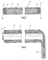
- Fig. 1 illustrated endoscope is provided in its entirety by the reference numeral 10.
- the endoscope 10 has an elongate shaft 12 which is provided on the proximal side with a housing 14.
- an optical fiber connection 16 extends away from the housing 14.
- the endoscope 10 is not shown in the final assembled state in the region of its housing 14, for clarity, the optical elements contained in the housing 14 and the final eyepiece shell are not shown.
- the shaft 12 of the endoscope 10, as well as from the sectional view of Fig. 2 can be seen, consists of an outer tube 18, in which a smaller diameter inner tube 20 is received.
- the inner tube 20 is arranged off-center, ie it lies along an outer surface line on an inner side the outer tube 18, as that in particular from the sectional view of Fig. 2 is apparent.
- the interior of the inner tube 20 constitutes a first tubular channel 21 for receiving the image-conducting components of the endoscope 10.
- Fig. 1 For example, only a few of these image-guiding elements are shown, namely two rod lenses 22 and a closure window 24 terminating proximally the first tubular channel 21. Between the outside of the inner tube 20 and the inside of the outer tube 18, a second channel 26 is formed, which is in the region of the shaft 12 has a crescent-shaped cross-section, as that in particular Fig. 2 is apparent.
- an assembly 38 of a flexible tube 28 and therein light guides 30 is received in the form of a bundle of glass fibers.
- the structure of the assembly 38 is initially on hand of Fig. 3 be described in more detail.
- the assembly 38 consists, as mentioned, of a flexible hose 28 made of plastic material.
- the material is a shrinkable plastic material.
- a bundle of glass fibers is inserted, whose length is chosen so that the opposite ends 32 and 33 of the flexible tube 28 slightly, about 1 cm, are surmounted.
- the bundle of glass fibers provides the optical waveguide 30.
- the glass fibers are connected to one another via an adhesive 34 and to the inside of the flexible hose 28.
- the adhesive 34 is applied and selected so that a sealing finish is granted, so that no contamination such as moisture or superheated steam can enter the interior of the flexible hose 28 from the outside.
- the optical waveguide 30 in the flexible tube 28 For introducing the optical waveguide 30 in the flexible tube 28, this can be aligned vertically hanging, and in one end, namely in the upper end, for example, the end 33, a funnel-shaped expanded outward insertion aid are inserted.
- the light guides 30 are introduced as glass fiber bundles from top to bottom.
- the glass fibers are slightly moistened with a slightly evaporable moistening agent, whereby they are held together by a non-spliced, about rod-shaped bundle by adhesion forces.
- the adhesive 34 is introduced in each case in the region of the ends 32 and 33 and optionally cured with the aid of heat. A possible shrinkage of the flexible tube 28 of shrinkable material in this curing in the region of the ends 32 and 33 is taken into account.
- the in Fig. 3 shown assembly 38 is now inserted into the second channel 26 of the endoscope 10, for example, inserted, from distal to proximal, ie in the representation of Fig. 1 left to right.
- the assembly 38 can thereby be inserted in a completely straight alignment or also screwed in, so that it at the proximal end of the still open housing 14 stands out.
- the lateral optical fiber connection 16 is not yet inserted into the housing 14.
- the optical fiber connector 16 is slid over this laterally depending end of the assembly 38 and used.
- the circumference of the flexible tube 28 is now chosen so that it can conform to the crescent-shaped cross-sectional contour of the second channel 28, as shown in particular in the sectional view of Fig. 2 evident.
- the individual glass fibers of the bundle which as a whole build up the light guide 30, are distributed uniformly in the crescent-shaped region.
- the hose 28 is removed with a circular cross section.
- the light guides 30 in the interior of the tube 28 are completely protected and fastened only via the end-side proximal and distal adhesive spots.
- certain movements, in particular thermal expansions in the Sterilisierzyklen possible if the endoscope 10 is used for the medical field.
- it can also compensate for the corresponding thermal expansion stresses, for example, when used in a warm or hot room.
- the material and the geometry of the flexible tube 28 may be selected so that different fixing points are formed with the inner wall of the second channel 26 and the light guide terminal 16 by the shrinking process.
- the material of the tube 28 beads or bulges that get a certain axial jamming with the walls surrounding the flexible tube 28 during the radial contraction during shrinking.
- a flexible hose 42 is provided, in the interior of which light guide 44 are introduced, wherein here also the light guide 44 consist of a bundle of fine light-conducting glass fibers.
- the light guides 44 were previously impregnated over their entire length with an adhesive 45.
- a core 46 is driven in, and to facilitate insertion, it may optionally have a tip.
- the length of the light guide 44 is chosen so that it at one end, the later the distal end is slightly protruding, about 1 cm, and at the opposite end there is a longer exposed strand 50.
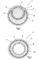
- the shaft 52 of an endoscope shown there has an outer tube 54, in which an inner tube 56 is concentrically received.
- the interior of the inner tube 56 in turn delimits here a first channel 57, which is provided for receiving the image-guiding system, that is, for example, the lenses described above, etc.
- the annular space in the cross section around the outside of the inner tube 56 and the inside of the outer tube 54 is the second channel 58 for receiving the photoconductive system.
- the core 46 has an outer diameter which corresponds approximately to the outer diameter of the inner tube 56.
- the in Fig. 4 shown assembly for example, pushed from the proximal end through the housing of the endoscope and placed so that the core 46 is approximately in alignment with the inner tube 46.
- the assembly of optical fiber 44 and flexible hose 42 can be deported directly from the core 46 and inserted into the second channel 58.
- the exposed strand 50 can then be inserted into the lateral fiber optic port; It can also be pushed over before a corresponding hose. It is also possible to slide over the outside of the shaft 52 a further tube, so that then the hollow cylindrical Assembly has a corresponding flexible hose both on the inside and on the outside.
- the distally protruding ends 48 of the glass fibers serve to be finally sealingly bonded to the distal end of the endoscope, as previously in the embodiment of Fig. 1 has been described.
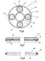
- Fig. 6 is a cross section of a shaft 62 is shown, which is similar to that described above from an outer tube 64 and an inner tube 66 concentrically arranged thereon.
- the inner tube 66 again delimits the first channel 67 for receiving the image-guiding system.
- a second channel 68 which is bounded by the outside of the inner tube 66 and the inside of the outer tube 64 and is of hollow cylindrical shape.
- this hollow cylindrical second channel 68 now four assembly copies 70, 71, 72, 73 are inserted, as previously in Fig. 3 have been described. These are arranged so that they are each offset by 90 ° to each other.
- Each individual assembly here representative only the assembly 70 is designated, then again consists of a flexible hose 74, in the interior of which a light guide 76 is composed of a bundle of fine glass fibers.
- the holder may be made mechanically, namely by the spacers that hold the inner tube 66 in coaxial alignment with the outer tube 64. These spacers consist of at least two or more axially spaced rings which are pushed onto the inner tube 66 and the four by 90 ° have offset passage openings through which the assembly specimens 70, 71, 72, 73 are pushed.
- FIGS. 7 and 8 It is shown how a previously described assembly of tube and light guide can be accomplished when an extremely long and thin endoscope is present. Here it may possibly be difficult to safely insert the optical fibers into an interior of a hose.
- a corresponding rectangular strip 80 is provided, which is provided over a longitudinal edge with an adhesive edge 82.
- the light guide 44 that is, a bundle of glass fibers, placed, and then the strip 80 is formed into a tube, wherein first one end is turned over, as shown by an arrow 89, and then the other end this is folded overlapping, as shown by an arrow 90, which is then accomplished by the adhesive edge 82 a fixation to a tubular body.
Landscapes
- Health & Medical Sciences (AREA)
- Life Sciences & Earth Sciences (AREA)
- Surgery (AREA)
- Physics & Mathematics (AREA)
- Engineering & Computer Science (AREA)
- Optics & Photonics (AREA)
- Biomedical Technology (AREA)
- Molecular Biology (AREA)
- Pathology (AREA)
- Nuclear Medicine, Radiotherapy & Molecular Imaging (AREA)
- Biophysics (AREA)
- Heart & Thoracic Surgery (AREA)
- Medical Informatics (AREA)
- Radiology & Medical Imaging (AREA)
- Animal Behavior & Ethology (AREA)
- General Health & Medical Sciences (AREA)
- Public Health (AREA)
- Veterinary Medicine (AREA)
- Manufacturing & Machinery (AREA)
- Endoscopes (AREA)
Claims (16)
- Procédé pour assembler un endoscope (10) comprenant un premier canal tubulaire (21, 57, 67) recevant des composants conducteurs d'images (22) et un deuxième canal (26, 58, 68) recevant des conducteurs de lumière (30, 44, 76, 84), les conducteurs de lumière (30, 44, 76, 84) étant introduits dans un tuyau flexible (28, 42, 74, 86) et l'ensemble (38, 70-73) composé du tuyau (28, 42, 74, 86) et des conducteurs de lumière (30, 44, 76, 84) étant introduit dans le deuxième canal (26, 58, 68), caractérisé en ce que les conducteurs de lumière (30, 44, 76, 84) sont fixés dans le tuyau (42) et les conducteurs de lumière (30, 44, 76, 84) sont pourvus d'une longueur telle qu'ils dépassent des deux côtés du tuyau (28, 42, 74, 86), un tuyau (28, 42, 74, 86) en matériau rétractable étant utilisé et le tuyau (28) étant rétracté après l'introduction dans le deuxième canal.
- Procédé selon la revendication 1, caractérisé en ce que les conducteurs de lumière (30) sont fixés dans la région des extrémités de tuyau (32, 33).
- Procédé selon la revendication 1 ou 2, caractérisé en ce que les conducteurs de lumière (44) sont fixés dans le tuyau (42) au moyen d'un produit adhésif (45).
- Procédé selon la revendication 3, caractérisé en ce que les collages sont réalisés de manière que les conducteurs de lumière (30) soient fixés de manière étanche dans la région des extrémités de tuyau (32, 33).
- Procédé selon l'une des revendications 1 à 4, caractérisé en ce que dans le cas d'un deuxième canal cylindrique creux (68), plusieurs tuyaux (74) sont introduits en étant répartis sur la circonférence.
- Procédé selon la revendication 5, caractérisé en ce que quatre tuyaux (74) décalés chaque fois d'environ 90° sur la circonférence sont introduits.
- Procédé selon l'une des revendications 1 à 4, caractérisé en ce que dans le cas d'un deuxième canal cylindrique creux (58), un ensemble composé du tuyau (42) et de conducteurs de lumière (44), qui présente un noyau central (46), est réalisé.
- Procédé selon la revendication 7, caractérisé en ce que les conducteurs de lumière (44) sont imprégnés d'un produit adhésif (45) et le produit adhésif (45) est durci avec le noyau (46) encore inséré.
- Procédé selon la revendication 7 ou 8, caractérisé en ce qu'un tuyau est également monté au-dessus du noyau (46).
- Procédé selon la revendication 1, caractérisé en ce que le tuyau est pré-rétracté avant l'introduction dans le deuxième canal.
- Procédé selon l'une des revendications 3 à 10, caractérisé en ce que le durcissement du produit adhésif et la rétraction du tuyau sont effectués en même temps sous l'action de la chaleur.
- Endoscope comprenant un premier canal tubulaire (21, 57, 67) recevant des composants conducteurs d'images (22) et un deuxième canal (26, 58, 68) recevant des conducteurs de lumière (30, 44, 76, 84), l'ensemble (38, 70-73) composé des conducteurs de lumière (30, 44, 76, 84) et d'un tuyau (28, 42, 74, 86) étant logé dans le deuxième canal (26, 58, 68), caractérisé en ce que les conducteurs de lumière (30, 44, 76, 84) sont logés dans un tuyau flexible rétracté (28, 42, 74, 86), les conducteurs de lumière (30, 44, 76, 84) étant fixés dans le tuyau et présentant une longueur telle qu'ils dépassent des deux côtés du tuyau.
- Endoscope selon la revendication 12, caractérisé en ce que les conducteurs de lumière (30) sont fixés dans la région des extrémités de tuyau (32, 33).
- Endoscope selon la revendication 12 ou 13, caractérisé en ce que les conducteurs de lumière (44) sont fixés dans le tuyau (42) au moyen d'un produit adhésif (45).
- Endoscope selon la revendication 14, caractérisé en ce que les collages sont réalisés de manière que les conducteurs de lumière (30) soient fixés de manière étanche dans la région des extrémités de tuyau (32, 33).
- Endoscope selon l'une des revendications 12 à 15, caractérisé en ce que le tuyau flexible (28) est fixé dans le deuxième canal (26) après l'opération de rétraction.
Applications Claiming Priority (3)
| Application Number | Priority Date | Filing Date | Title |
|---|---|---|---|
| DE10307903 | 2003-02-18 | ||
| DE10307903A DE10307903A1 (de) | 2003-02-18 | 2003-02-18 | Verfahren zum Montieren eines Endoskopes |
| PCT/EP2004/000766 WO2004073507A1 (fr) | 2003-02-18 | 2004-01-29 | Procede pour monter un endoscope |
Publications (2)
| Publication Number | Publication Date |
|---|---|
| EP1596703A1 EP1596703A1 (fr) | 2005-11-23 |
| EP1596703B1 true EP1596703B1 (fr) | 2009-04-08 |
Family
ID=32797726
Family Applications (1)
| Application Number | Title | Priority Date | Filing Date |
|---|---|---|---|
| EP04706138A Expired - Lifetime EP1596703B1 (fr) | 2003-02-18 | 2004-01-29 | Procede pour monter un endoscope |
Country Status (4)
| Country | Link |
|---|---|
| US (1) | US7662096B2 (fr) |
| EP (1) | EP1596703B1 (fr) |
| DE (2) | DE10307903A1 (fr) |
| WO (1) | WO2004073507A1 (fr) |
Families Citing this family (42)
| Publication number | Priority date | Publication date | Assignee | Title |
|---|---|---|---|---|
| NL1006944C2 (nl) | 1997-09-04 | 1999-03-11 | Mark Hans Emanuel | Chirurgische endoscopische snij-inrichting. |
| US7226459B2 (en) | 2001-10-26 | 2007-06-05 | Smith & Nephew, Inc. | Reciprocating rotary arthroscopic surgical instrument |
| DE10245009B4 (de) * | 2002-09-20 | 2007-09-06 | Karl Storz Gmbh & Co. Kg | Medizinisches Instrument zum Saugen und Spülen und Verfahren zu seiner Herstellung |
| US8062214B2 (en) | 2004-08-27 | 2011-11-22 | Smith & Nephew, Inc. | Tissue resecting system |
| EP1887946A2 (fr) * | 2005-06-06 | 2008-02-20 | The Board Of Regents, The University Of Texas System | Tomographie a coherence optique utilisant une largeur de bande a resolution spectrale |
| DE102005051208A1 (de) * | 2005-10-18 | 2007-04-19 | Karl Storz Gmbh & Co. Kg | Endoskop und Verfahren zu seiner Herstellung |
| DE102005051209A1 (de) * | 2005-10-18 | 2007-04-19 | Karl Storz Gmbh & Co. Kg | Endoskop |
| DE102005051207A1 (de) * | 2005-10-18 | 2007-04-19 | Karl Storz Gmbh & Co. Kg | Endoskop und Verfahren zu seiner Herstellung |
| DE202005017518U1 (de) * | 2005-11-04 | 2007-03-08 | Kämpfert, Marco | Stabendoskop |
| US7333700B2 (en) * | 2006-06-01 | 2008-02-19 | University Of Washington | Scanning apparatus and endoscope |
| DE102007002042B4 (de) * | 2007-01-13 | 2008-09-18 | Olympus Winter & Ibe Gmbh | Endoskopoptik mit Lichtleitfaserbündel |
| US20080269556A1 (en) * | 2007-04-02 | 2008-10-30 | Jagasia Ashok A | Endoscope with flexible tip |
| DE102009037317A1 (de) * | 2009-08-14 | 2011-02-17 | Karl Storz Gmbh & Co. Kg | Vorrichtung und Verfahren zur Zentrierung von Innen- und Außenrohr eines Endoskops |
| US8627579B2 (en) * | 2010-03-30 | 2014-01-14 | Verizon New York Inc. | Heat gun air flow-extenders |
| US9155454B2 (en) | 2010-09-28 | 2015-10-13 | Smith & Nephew, Inc. | Hysteroscopic system |
| DE102010056025A1 (de) | 2010-12-27 | 2012-06-28 | Olympus Winter & Ibe Gmbh | Endoskop mit einem Schaftrohr |
| CN102798928A (zh) * | 2011-05-27 | 2012-11-28 | 吕路可 | 可传递光线的复合塑料管体 |
| DE102012200794A1 (de) * | 2012-01-20 | 2013-07-25 | Karl Storz Gmbh & Co. Kg | Lichtleiter mit einem Bündel von lichtleitenden Fasern und ein Verfahren zur Biegung des Lichtleiters |
| ES2738530T3 (es) * | 2013-02-25 | 2020-01-23 | Steris Instrument Man Services Inc | Parte distal de endoscopio rígido |
| WO2016100522A1 (fr) | 2014-12-16 | 2016-06-23 | Smith & Nephew, Inc. | Dispositif chirurgical avec système d'extraction tissulaire incorporé |
| DE102015000773B4 (de) * | 2015-01-26 | 2021-09-16 | Karl Storz Se & Co. Kg | Endoskop und Verfahren zur Herstellung eines Endoskops |
| WO2016122500A1 (fr) | 2015-01-28 | 2016-08-04 | Smith & Nephew, Inc. | Système de résection de tissu |
| WO2016191422A1 (fr) | 2015-05-26 | 2016-12-01 | Covidien Lp | Systèmes et procédés pour la génération d'un palier fluide pour une procédure de fonctionnement |
| US10804769B2 (en) | 2015-06-17 | 2020-10-13 | Covidien Lp | Surgical instrument with phase change cooling |
| US11864735B2 (en) | 2016-05-26 | 2024-01-09 | Covidien Lp | Continuous flow endoscope |
| US10299819B2 (en) | 2016-07-28 | 2019-05-28 | Covidien Lp | Reciprocating rotary surgical cutting device and system for tissue resecting, and method for its use |
| US10299803B2 (en) | 2016-08-04 | 2019-05-28 | Covidien Lp | Self-aligning drive coupler |
| US10772654B2 (en) | 2017-03-02 | 2020-09-15 | Covidien Lp | Fluid-driven tissue resecting instruments, systems, and methods |
| DE102017111306A1 (de) | 2017-05-23 | 2018-11-29 | Karl Storz Se & Co. Kg | Endoskop |
| US10869684B2 (en) | 2018-02-13 | 2020-12-22 | Covidien Lp | Powered tissue resecting device |
| US11547815B2 (en) | 2018-05-30 | 2023-01-10 | Covidien Lp | Systems and methods for measuring and controlling pressure within an internal body cavity |
| US11065147B2 (en) | 2018-10-18 | 2021-07-20 | Covidien Lp | Devices, systems, and methods for pre-heating fluid to be introduced into a patient during a surgical procedure |
| US11083481B2 (en) | 2019-02-22 | 2021-08-10 | Covidien Lp | Tissue resecting instrument including an outflow control seal |
| US11154318B2 (en) | 2019-02-22 | 2021-10-26 | Covidien Lp | Tissue resecting instrument including an outflow control seal |
| US10898218B2 (en) | 2019-02-25 | 2021-01-26 | Covidien Lp | Tissue resecting device including a motor cooling assembly |
| CN113840578B (zh) | 2019-05-29 | 2024-06-18 | 柯惠有限合伙公司 | 用于管理患者体液的宫腔镜检查系统和方法 |
| US11890237B2 (en) | 2019-10-04 | 2024-02-06 | Covidien Lp | Outflow collection vessels, systems, and components thereof for hysteroscopic surgical procedures |
| US11452806B2 (en) | 2019-10-04 | 2022-09-27 | Covidien Lp | Outflow collection vessels, systems, and components thereof for hysteroscopic surgical procedures |
| DE102020105469A1 (de) * | 2020-03-02 | 2021-09-02 | Karl Storz Se & Co. Kg | Endoskop mit einer Lichtleitereinrichtung, Verfahren zur Herstellung eines Endoskops mit einer Lichtleitereinrichtung und Verwendung eines Verfahrens zur Herstellung eines Endoskops |
| US11571233B2 (en) | 2020-11-19 | 2023-02-07 | Covidien Lp | Tissue removal handpiece with integrated suction |
| US12303109B2 (en) | 2021-12-22 | 2025-05-20 | Covidien Lp | Surgical systems and methods for component cooling while warming fluid to be introduced during a surgical procedure |
| US12478359B2 (en) | 2022-09-13 | 2025-11-25 | Covidien Lp | Surgical instruments and manufacturing methods facilitating durable engagement between components of different materials |
Family Cites Families (30)
| Publication number | Priority date | Publication date | Assignee | Title |
|---|---|---|---|---|
| DE1869483U (de) * | 1963-02-01 | 1963-03-28 | Wolf Gmbh Richard | Endoskop. |
| US3496931A (en) * | 1966-09-20 | 1970-02-24 | Pilling Co | Illuminating endoscope with oval fiber optic channel |
| US3699950A (en) * | 1970-07-02 | 1972-10-24 | Dyonics Inc | Flexible optical light pipes used for surgery |
| GB1463350A (en) * | 1974-12-05 | 1977-02-02 | Bowthorpe Hellermann Ltd | Light guide contact |
| US4173392A (en) * | 1977-07-20 | 1979-11-06 | American Hospital Supply Corporation | Glass fiber light guide and method of making the same |
| JPH0115361Y2 (fr) * | 1979-02-10 | 1989-05-09 | ||
| US5041108A (en) * | 1981-12-11 | 1991-08-20 | Pillco Limited Partnership | Method for laser treatment of body lumens |
| JPS58105202A (ja) * | 1981-12-18 | 1983-06-23 | Olympus Optical Co Ltd | 光学繊維束を用いた照明装置 |
| US4652288A (en) * | 1984-08-04 | 1987-03-24 | Horiba, Ltd. | Method of producing infrared image guide |
| US4657742A (en) * | 1985-07-01 | 1987-04-14 | Ppg Industries, Inc. | Packed fiber glass reaction vessel |
| EP0212426B1 (fr) * | 1985-08-16 | 1992-07-22 | Olympus Optical Co., Ltd. | Endoscope |
| JPH0785129B2 (ja) * | 1986-02-04 | 1995-09-13 | 旭光学工業株式会社 | 内視鏡用光学繊維束 |
| US4813400A (en) * | 1986-08-08 | 1989-03-21 | Olympus Optical Co., Ltd. | Optical fiber assembly for an endoscope |
| US4832003A (en) * | 1986-09-12 | 1989-05-23 | Olympus Optical Co., Ltd. | Electronic endoscope tip |
| GB2197496B (en) * | 1986-11-13 | 1990-01-24 | Keymed | Borescopes. |
| US4782819A (en) * | 1987-02-25 | 1988-11-08 | Adair Edwin Lloyd | Optical catheter |
| DE3822885C2 (de) * | 1987-07-06 | 1994-06-01 | Asahi Optical Co Ltd | Optisches Kabel und Verfahren zu dessen Herstellung |
| JPH01126616A (ja) * | 1987-11-11 | 1989-05-18 | Olympus Optical Co Ltd | 内視鏡における光学繊維束の組付け方法 |
| IT1228288B (it) * | 1989-01-09 | 1991-06-07 | Zambon Spa | Composti ad attivita' antiserotoninica |
| US5460781A (en) * | 1989-10-27 | 1995-10-24 | Fujirebio Kabushiki Kaisha | Hemoglobin sampler |
| JP3001117B2 (ja) * | 1990-05-28 | 2000-01-24 | 日本電信電話株式会社 | 光ケーブルとその製造方法 |
| US5305736A (en) * | 1991-04-26 | 1994-04-26 | Asahi Kogaku Kogyo Kabushiki Kaisha | Distal end part of endoscope |
| DE4207092A1 (de) * | 1992-03-06 | 1993-09-16 | Schott Glaswerke | Endoskop |
| US5354518A (en) * | 1993-02-11 | 1994-10-11 | Sherwood Medical Company | Method for manufacturing a fiberscopic catheter |
| US5662817A (en) * | 1994-06-28 | 1997-09-02 | Nec Corporation | Method for forming tip of array optical fiber using etching process |
| JP3291177B2 (ja) | 1995-10-31 | 2002-06-10 | 古河電気工業株式会社 | チューブ付き光ファイバ心線の端末部 |
| US5953477A (en) * | 1995-11-20 | 1999-09-14 | Visionex, Inc. | Method and apparatus for improved fiber optic light management |
| US6337737B1 (en) * | 2001-03-09 | 2002-01-08 | Ciena Corporation | Fiber-Bragg-grating-based strain measuring apparatus, system and method |
| US6760523B2 (en) * | 2001-06-20 | 2004-07-06 | Alcatel | Tape based high fiber count cable |
| JP2003070722A (ja) * | 2001-09-06 | 2003-03-11 | Pentax Corp | プローブ及び蛍光診断システム |
-
2003
- 2003-02-18 DE DE10307903A patent/DE10307903A1/de not_active Withdrawn
-
2004
- 2004-01-29 WO PCT/EP2004/000766 patent/WO2004073507A1/fr not_active Ceased
- 2004-01-29 EP EP04706138A patent/EP1596703B1/fr not_active Expired - Lifetime
- 2004-01-29 DE DE502004009312T patent/DE502004009312D1/de not_active Expired - Lifetime
-
2005
- 2005-08-18 US US11/206,694 patent/US7662096B2/en not_active Expired - Lifetime
Also Published As
| Publication number | Publication date |
|---|---|
| US7662096B2 (en) | 2010-02-16 |
| EP1596703A1 (fr) | 2005-11-23 |
| US20060036132A1 (en) | 2006-02-16 |
| WO2004073507A1 (fr) | 2004-09-02 |
| DE502004009312D1 (de) | 2009-05-20 |
| DE10307903A1 (de) | 2004-09-02 |
Similar Documents
| Publication | Publication Date | Title |
|---|---|---|
| EP1596703B1 (fr) | Procede pour monter un endoscope | |
| EP1083821B1 (fr) | Gaine protectrice utilisee lors de la sterilisation d'endoscopes souples | |
| EP0842633B1 (fr) | Endoscope électronique pouvant être entièrement stérilisé à l'autoclave | |
| DE4115419C2 (de) | Verfahren zum Herstellen eines flexiblen Rohres für ein Endoskop und entsprechend hergestelltes flexibles Rohr | |
| EP1031054B1 (fr) | Procede de montage de lentilles en forme de barres dans un endoscope et endoscope dote de telles lentilles en forme de barres | |
| EP1776917B1 (fr) | Endoscope | |
| DE3909290A1 (de) | Umhuelltes endoskop | |
| WO2019211456A1 (fr) | Déflexion endoscopique comprenant un mécanisme rabattable distal | |
| EP1776918B1 (fr) | Endoscope et procédé de sa fabrication | |
| DE3737425A1 (de) | Endoskop mit verbessertem optischen system, sowie verfahren zur herstellung des optischen systems | |
| DE2814236A1 (de) | Modulstablinsenanordnung und verfahren zu ihrer herstellung | |
| DE2743781A1 (de) | Endoskop | |
| DE102018110228A1 (de) | Vorrichtung und Verfahren zur kontaminationsfreien Durchführung einer endoskopischen Untersuchung | |
| DE102008037260A1 (de) | Verfahren zum Entfernen von Nierensteinen und für dieses Verfahren geeignetes Endoskop | |
| WO2017025434A1 (fr) | Tête d'endoscope, endoscope, capuchon et procédé de formation d'un capuchon | |
| EP2263518A1 (fr) | Endoscope doté d'une fenêtre et procédé de fabrication d'un endoscope | |
| DE102015000773A1 (de) | Endoskop und Verfahren zur Herstellung eines Endoskops | |
| DE102016111363B4 (de) | Endoskop mit flexibel verklebtem Lichtleiter | |
| DE4238977C2 (de) | Vorrichtung zur Beleuchtung und Inspektion von Hohl- und Zwischenräumen | |
| EP1777573A1 (fr) | Endoscope et procédé pour sa fabrication | |
| DE20320943U1 (de) | Endoskop | |
| DE102021105244B3 (de) | Endoskop | |
| DE202010001630U1 (de) | Endoskopoptik und Endoskop | |
| DE2926919C2 (de) | Endoskop | |
| EP3747341B1 (fr) | Endoscope pourvu de conducteur de lumière collé |
Legal Events
| Date | Code | Title | Description |
|---|---|---|---|
| PUAI | Public reference made under article 153(3) epc to a published international application that has entered the european phase |
Free format text: ORIGINAL CODE: 0009012 |
|
| 17P | Request for examination filed |
Effective date: 20050914 |
|
| AK | Designated contracting states |
Kind code of ref document: A1 Designated state(s): AT BE BG CH CY CZ DE DK EE ES FI FR GB GR HU IE IT LI LU MC NL PT RO SE SI SK TR |
|
| AX | Request for extension of the european patent |
Extension state: AL LT LV MK |
|
| DAX | Request for extension of the european patent (deleted) | ||
| RBV | Designated contracting states (corrected) |
Designated state(s): DE FR GB IT |
|
| 17Q | First examination report despatched |
Effective date: 20080409 |
|
| GRAP | Despatch of communication of intention to grant a patent |
Free format text: ORIGINAL CODE: EPIDOSNIGR1 |
|
| GRAS | Grant fee paid |
Free format text: ORIGINAL CODE: EPIDOSNIGR3 |
|
| GRAA | (expected) grant |
Free format text: ORIGINAL CODE: 0009210 |
|
| AK | Designated contracting states |
Kind code of ref document: B1 Designated state(s): DE FR GB IT |
|
| REG | Reference to a national code |
Ref country code: GB Ref legal event code: FG4D Free format text: NOT ENGLISH |
|
| REF | Corresponds to: |
Ref document number: 502004009312 Country of ref document: DE Date of ref document: 20090520 Kind code of ref document: P |
|
| PLBE | No opposition filed within time limit |
Free format text: ORIGINAL CODE: 0009261 |
|
| STAA | Information on the status of an ep patent application or granted ep patent |
Free format text: STATUS: NO OPPOSITION FILED WITHIN TIME LIMIT |
|
| 26N | No opposition filed |
Effective date: 20100111 |
|
| REG | Reference to a national code |
Ref country code: FR Ref legal event code: PLFP Year of fee payment: 13 |
|
| PGFP | Annual fee paid to national office [announced via postgrant information from national office to epo] |
Ref country code: IT Payment date: 20160111 Year of fee payment: 13 |
|
| REG | Reference to a national code |
Ref country code: FR Ref legal event code: PLFP Year of fee payment: 14 |
|
| REG | Reference to a national code |
Ref country code: FR Ref legal event code: PLFP Year of fee payment: 15 |
|
| REG | Reference to a national code |
Ref country code: DE Ref legal event code: R081 Ref document number: 502004009312 Country of ref document: DE Owner name: KARL STORZ SE & CO. KG INTELLECTUAL PROPERTY, DE Free format text: FORMER OWNER: KARL STORZ GMBH & CO. KG, 78532 TUTTLINGEN, DE Ref country code: DE Ref legal event code: R082 Ref document number: 502004009312 Country of ref document: DE Representative=s name: WITTE, WELLER & PARTNER PATENTANWAELTE MBB, DE Ref country code: DE Ref legal event code: R081 Ref document number: 502004009312 Country of ref document: DE Owner name: KARL STORZ SE & CO. KG, DE Free format text: FORMER OWNER: KARL STORZ GMBH & CO. KG, 78532 TUTTLINGEN, DE |
|
| PG25 | Lapsed in a contracting state [announced via postgrant information from national office to epo] |
Ref country code: IT Free format text: LAPSE BECAUSE OF NON-PAYMENT OF DUE FEES Effective date: 20170129 |
|
| PGFP | Annual fee paid to national office [announced via postgrant information from national office to epo] |
Ref country code: GB Payment date: 20221221 Year of fee payment: 20 Ref country code: FR Payment date: 20221220 Year of fee payment: 20 |
|
| PGFP | Annual fee paid to national office [announced via postgrant information from national office to epo] |
Ref country code: DE Payment date: 20221220 Year of fee payment: 20 |
|
| P01 | Opt-out of the competence of the unified patent court (upc) registered |
Effective date: 20230527 |
|
| REG | Reference to a national code |
Ref country code: DE Ref legal event code: R071 Ref document number: 502004009312 Country of ref document: DE |
|
| REG | Reference to a national code |
Ref country code: GB Ref legal event code: PE20 Expiry date: 20240128 |
|
| PG25 | Lapsed in a contracting state [announced via postgrant information from national office to epo] |
Ref country code: GB Free format text: LAPSE BECAUSE OF EXPIRATION OF PROTECTION Effective date: 20240128 |