EP1597112B1 - Retroviseur exterieur pour vehicules automobiles - Google Patents
Retroviseur exterieur pour vehicules automobiles Download PDFInfo
- Publication number
- EP1597112B1 EP1597112B1 EP04713455A EP04713455A EP1597112B1 EP 1597112 B1 EP1597112 B1 EP 1597112B1 EP 04713455 A EP04713455 A EP 04713455A EP 04713455 A EP04713455 A EP 04713455A EP 1597112 B1 EP1597112 B1 EP 1597112B1
- Authority
- EP
- European Patent Office
- Prior art keywords
- rearview mirror
- outside rearview
- mirror according
- mirror
- housing
- Prior art date
- Legal status (The legal status is an assumption and is not a legal conclusion. Google has not performed a legal analysis and makes no representation as to the accuracy of the status listed.)
- Expired - Lifetime
Links
Images


Classifications
-
- B—PERFORMING OPERATIONS; TRANSPORTING
- B60—VEHICLES IN GENERAL
- B60Q—ARRANGEMENT OF SIGNALLING OR LIGHTING DEVICES, THE MOUNTING OR SUPPORTING THEREOF OR CIRCUITS THEREFOR, FOR VEHICLES IN GENERAL
- B60Q1/00—Arrangement of optical signalling or lighting devices, the mounting or supporting thereof or circuits therefor
- B60Q1/26—Arrangement of optical signalling or lighting devices, the mounting or supporting thereof or circuits therefor the devices being primarily intended to indicate the vehicle, or parts thereof, or to give signals, to other traffic
- B60Q1/2661—Arrangement of optical signalling or lighting devices, the mounting or supporting thereof or circuits therefor the devices being primarily intended to indicate the vehicle, or parts thereof, or to give signals, to other traffic mounted on parts having other functions
- B60Q1/2665—Arrangement of optical signalling or lighting devices, the mounting or supporting thereof or circuits therefor the devices being primarily intended to indicate the vehicle, or parts thereof, or to give signals, to other traffic mounted on parts having other functions on rear-view mirrors
-
- B—PERFORMING OPERATIONS; TRANSPORTING
- B60—VEHICLES IN GENERAL
- B60R—VEHICLES, VEHICLE FITTINGS, OR VEHICLE PARTS, NOT OTHERWISE PROVIDED FOR
- B60R1/00—Optical viewing arrangements; Real-time viewing arrangements for drivers or passengers using optical image capturing systems, e.g. cameras or video systems specially adapted for use in or on vehicles
- B60R1/02—Rear-view mirror arrangements
- B60R1/06—Rear-view mirror arrangements mounted on vehicle exterior
-
- B—PERFORMING OPERATIONS; TRANSPORTING
- B60—VEHICLES IN GENERAL
- B60R—VEHICLES, VEHICLE FITTINGS, OR VEHICLE PARTS, NOT OTHERWISE PROVIDED FOR
- B60R1/00—Optical viewing arrangements; Real-time viewing arrangements for drivers or passengers using optical image capturing systems, e.g. cameras or video systems specially adapted for use in or on vehicles
- B60R1/12—Mirror assemblies combined with other articles, e.g. clocks
- B60R1/1207—Mirror assemblies combined with other articles, e.g. clocks with lamps; with turn indicators
Definitions
- the invention relates to an exterior rearview mirror for vehicles, preferably for motor vehicles, according to the preamble of claim 1.
- the invention has the object of providing the generic exterior rearview mirror in such a way that the lamp unit can be easily mounted with little installation space.
- the lighting unit is part of the add-on element, which is physically separated from the exterior rearview mirror.
- the lighting unit and the lighting means can therefore be easily manufactured and mounted.
- no installation space is needed.
- the housing of the lamp unit is received in the receiving space of the mirror base.
- the receiving space is formed by a recess in the mirror, in which the housing can be easily inserted.
- the wall of the attachment is located between the mirror and the body of the vehicle.
- the exterior rearview mirrors described below are intended for motor vehicles and each have at least one illumination that can be arranged and configured in different ways to fulfill different lighting functions.
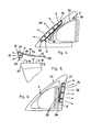
- the exterior rearview mirror according to FIGS. 1 and 2 has a mirror head 1 and a mirror 2, with which the exterior rearview mirror can be attached to the motor vehicle.
- a part of the door panel 3 of the motor vehicle is shown by way of example.
- the mirror 2 can be fixed to the door panel 3 in a known manner, for example by snapping, hanging, screwing or other known mounting options.
- the mirror head 1 is folded down relative to the mirror 2, preferably in the direction of travel to the rear and to the front.
- the exterior rearview mirror according to FIGS. 1 and 2 is designed as a single-axis mirror, in which the mirror head 1, when folded down, pivots forwards and backwards about the same upright axis. Since such swivel training in exterior rearview mirrors are known, they are not explained in detail.
- the mirror 2 has on its bottom 4 facing the bottom of a receiving space 5, in which a lamp unit 6 is housed.
- the underside 4 of the mirror base is correspondingly deformed (FIG. 2).
- the recording room 5 is approximately half the width of the mirror base 2 and is bounded on the outside by a rear wall 7 and in the direction of travel forward and backward by side walls 8, 9.
- a ceiling 10 which merges into an upward investment wall 11 of the mirror base 2 (Fig. 1).
- the investment wall 11 is advantageously covered with a seal 12.
- three sleeves 13 to 15 are provided in the abutment wall 11, which has approximately triangular outline in the exemplary embodiment, which protrude beyond the abutment wall 11, pass through the seal 12 and in the installed position in openings 16th 17 intervene in the door panel 3.
- the sleeves 13 to 15 cooperate with threaded bolts 18, with which the exterior rearview mirror is attached to the door panel 3.
- the lighting unit 6 is part of an attachment element 19, which is arranged in the installed position of the exterior rearview mirror between the door panel 3 and the mirror 2.
- the attachment member 19 has a housing 20, the outline shape of the inner shape of the receiving space 5 of the mirror base 2 is adapted.
- the housing 20 has a rear wall 21, a front wall 22, (not shown) side walls and a top wall 23. With these walls, the housing 20 is in the installed position on the rear wall 7, the side walls 8, 9 and the ceiling 10 of the receiving space 5 at , The housing 20 is closed downwardly towards the floor by a lens 24 through which the light emitted by bulbs 25 in the housing 20 falls downwardly toward the floor.
- the bulbs 25 accommodated in the housing 20 are preferably LEDs, but may also be incandescent lamps or other bulbs known in automotive engineering.
- the lens 24 is flat in the embodiment and is in the installed position flush with the bottom 4 of the mirror base 2.
- the lens 24 may, for example according to the design specification also the mirror 2 to be arched accordingly.
- a rear wall 26 which is in extension of the rear wall 21 of the housing 20 and in the installed position against the seal 12 flat.
- the rear wall 26 has openings 27 for the passage of the sleeves 13 to 15 and for cables.
- the rear wall 26 is approximately adapted to the outline shape of the seal 12. From the rear wall 26 are latching hooks 28, which is associated with a corresponding (not shown) latching opening in the door panel 3.
- the illuminant unit 6 of the add-on element 19 forms an ambient lighting, which can be attached to the door panel 3 of the motor vehicle independently of the exterior rearview mirror by means of the latching hooks 28. It is notwithstanding the illustrated embodiment also possible to mount the attachment 19 on the door panel 3, screw or otherwise secure. It is also possible to attach the attachment member 19 on the mirror 2. Since the lighting unit 6 is part of the add-on element 19, the lighting unit does not have to be integrated into the mirror 2.
- the attachment element 19 is attached to the door panel 3. Subsequently, the mirror 2 including mirror head 1 is screwed to the door panel 3 with the threaded bolt 18 in a known manner.
- the rear wall 26 of the attachment element 19 is covered by the mirror 2, while the lighting unit 6 is accommodated in the receiving space 5 of the mirror 2.
- the attachment 19 is held securely. With the light radiated downwards by the light sources 25, the area next to the motor vehicle door is illuminated, so that this area is optimally illuminated when the vehicle is to be climbed in the dark.
- the attachment element 19 is formed in one piece except for the lens 24 and is advantageously made of a plastic.
- a seal 29 is provided which prevents ingress of dirt into the receiving space 5.
- Fig. 3 shows an exterior rearview mirror in two-axle design.
- the mirror head 1 is pivotable in and against the direction of travel of the motor vehicle about an axis 30, 31.
- the two pivot axes are parallel to each other and extend as the pivot axis of the exterior rearview mirror according to FIGS. 1 and 2 upwards.
- Such ZweiachsLite are known and are therefore not explained in detail.
- the mirror 2 is provided as in the previous embodiment on its underside with the receiving space 5, which receives the lighting unit 6 of the add-on element 19.
- the receiving space 5 is not centered in the bottom 4, but is provided in the direction of travel to the rear offset in the bottom 4.
- the receiving space 5 is formed substantially the same as in the previous embodiment.
- the receiving space 5 may be provided centrally in the underside 4 of the mirror base 2 even at a two-axis mirror.
- the door panel 3 facing side of the contact wall 11 of the mirror base 2 is covered with the seal 12, which is designed as a flat sealing disc and can be attached to the contact wall 11. But it is also possible to clamp the seal 12 between the abutment wall 11 of the mirror base 2 and the rear wall 26 of the attachment element 19.
- the rear wall 26 is integrally formed with the housing 20 of the lamp unit 6, in which the bulbs 25 are housed. In the installed position, the bulbs 25 radiate the light down to the ground.
- the attachment member 19 is a dimensionally stable, but partially elastic component, which is arranged as an independent unit between the mirror 2 and the door panel 3.
- the attachment member 19 forms according to the previous embodiment, a kind of adapter piece between the mirror 2 and the vehicle door. 3
- the attachment element 19 is a separate component which is installed between the mirror base 2 and the door panel 3.
- the attachment element 19 projects beyond its circumference via the mirror base 2 (FIG. 4).
- the lighting unit 6 of the attachment is adjacent to the front in the direction of travel, obliquely upward edge 32 of the mirror 2 arranged.
- the lighting unit 6 has the housing 20 in which the bulbs 25 are housed.
- the bulbs 25 are disposed within the housing 20 adjacent to the edge 32 of the mirror base 2.
- the housing 20 is closed in the direction of travel forward through the lens 24, which lies flush in the outside of the attachment element 19.
- the lens 24 In cross-section (FIG. 5), the lens 24 is convexly curved.
- the lens 24 may also have any other suitable cross-sectional shape.
- the attachment 19 has in view triangular shape. Its edges are approximately parallel to the edges of the mirror base 2.
- the attachment member 19 may consist entirely of soft, rubbery material. Of course, an embodiment of this attachment element 19 in a combination of soft and hard, dimensionally stable plastic is conceivable.
- the light emitted by the bulbs 25 light passes through the lens 24 in the direction of travel to the front.
- the lighting unit 6 forms a repeating flashing light.
- the housing 20 is formed integrally with the rear wall 26 of the attachment element 19. It lies flat in the installation position on the abutment wall 11 of the mirror base 2. He has the over the abutment wall 11 projecting sleeves 13, 14, which protrude through the openings 16, 17 in the rear wall 26 of the attachment member 19 and which cooperate with the threaded bolt 18 (Fig. 1) during assembly of the exterior rearview mirror.
- the light beams 33 of the bulbs 25 can be directed so that they are directed obliquely down to the ground.
- the lighting unit 6 of the add-on element 19 does not form a repeating flashing light, but an ambient light that illuminates the floor area next to the vehicle door.
- the lighting unit 6 can be used as Wiederholinkinkmple. In this case, it is advantageous to be able to operate the lighting means of the ambient light independently of the bulbs of the repeating flashing light.
- the illuminant unit 6 of the add-on element 19 is located on the upwardly directed edge 34 of the mirror base 2 in the direction of travel.
- the edge 34 is provided with the receiving space 5 designed as a recess in which the illuminant unit 6 is in the installed position.
- the housing 20 of the lighting unit 6 is applied to the walls of the receiving space 5 area.
- the lens 24 is flush in the outside of the edge 34 of the mirror base. 2
- the bulbs 25 are housed, emit their light in contrast to the previous embodiment in the direction of travel to the rear.
- the lighting unit 6 can also be used in this case as a repeating indicator.
- the light beams 33 can be directed in the desired direction, for example, by optics on the back of the lens 24 and / or by reflectors housed in the housing 20.
- the rear wall 26 connects, which is advantageously integrally formed with the housing and in the installed position rests flat against the abutment wall 11 of the mirror base 2. While in the embodiment of FIGS. 4 and 5, the housing 20 is provided on the front in the direction of travel edge of the rear wall 26, the housing 20 is in the embodiment of FIG. 6th and 7 at the rear in the direction of travel of the vehicle edge of the rear wall 26. At the opposite side of the housing 20, the rear wall 26 is angled at an acute angle. This angled edge 35 of the rear wall 26 touches the front in the direction of travel, upwardly directed edge 32 of the mirror base. 2
- the lighting unit 6 is part of the separate attachment element 19, which is arranged between the mirror 2 and the vehicle door.
- the attachment element 19 with the lighting unit 6 is advantageously formed in one piece.
- the attachment element 19 may consist of a hard material, preferably a corresponding plastic. It is also possible to produce the attachment element 19 of flexible material, so that it can simultaneously fulfill a sealing function between the exterior rearview mirror or its mirror base 2 and the door panel 3. It is also possible to make the attachment 19 partly of a hard material and partly of a flexible material. For example, it is possible to produce the housing 20 of the lighting unit 6 from a suitably solid material, while the rear wall 26 can be made of flexible material.
- the attachment element 19 is a separate component from the mirror, the interior of the mirror base 2 and in particular of the mirror head 1 is available for other installations.
- the drives for mirror glass adjustment and motorized adjustment of the mirror head 1 heating elements for the mirror glass, transmitter of garage door openers, speakers, antennas, GPS modules and the like can be easily installed in the mirror head 1.
Landscapes
- Engineering & Computer Science (AREA)
- Mechanical Engineering (AREA)
- Multimedia (AREA)
- Rear-View Mirror Devices That Are Mounted On The Exterior Of The Vehicle (AREA)
- Lighting Device Outwards From Vehicle And Optical Signal (AREA)
Claims (20)
- Rétroviseur extérieur pour véhicules, de préférence pour véhicules automobiles, comportant un pied de rétroviseur (2) et une tête de rétroviseur (1) ainsi qu'au moins une unité à moyen d'éclairage (6) qui présente au moins un moyen d'éclairage (25) et un boîtier (20) dans lequel est logé le moyen d'éclairage (25) et qui est situé dans une chambre de réception du pied de rétroviseur (2),
caractérisé en ce que la chambre de réception (5) est un renfoncement dans le pied de rétroviseur (2), dans lequel fait saillie le boîtier (20), et en ce que l'unité à moyen d'éclairage (6) fait partie d'un élément rapporté (19) qui est corporellement séparé du rétroviseur extérieur et qui présente une paroi (26) se trouvant entre le pied de rétroviseur (2) et la carrosserie (3) du véhicule. - Rétroviseur extérieur selon la revendication 1, caractérisé en ce que le boîtier (20) et la paroi (26) de l'élément rapporté (19) sont réalisés d'un seul tenant l'un avec l'autre.
- Rétroviseur extérieur selon la revendication 1 ou 2, caractérisé en ce que l'élément rapporté (19) présente au moins une partie à coopération de formes (28, 35).
- Rétroviseur extérieur selon la revendication 3, caractérisé en ce que la partie à coopération de formes (28) est formée par des crochets d'enclenchement.
- Rétroviseur extérieur selon la revendication 4, caractérisé en ce que la partie à coopération de formes (28) peut être enclenchée dans la carrosserie (3) du véhicule.
- Rétroviseur extérieur selon l'une des revendications 3 à 5, caractérisé en ce que la partie à coopération de formes (28, 35) fait saillie transversalement depuis la paroi (26) de l'élément rapporté (19).
- Rétroviseur extérieur selon la revendication 3 ou 6, caractérisé en ce que la partie à coopération de formes (35) est une partie coudée de la paroi (26) de l'élément rapporté (19).
- Rétroviseur extérieur selon l'une des revendications 1 à 7, caractérisé en ce que la chambre de réception (5) est formée par un tronçon conformé du pied de rétroviseur (2).
- Rétroviseur extérieur selon l'une des revendications 1 à 8, caractérisé en ce que la chambre de réception (5) est prévue sur la face inférieure (4) du pied de rétroviseur (2).
- Rétroviseur extérieur selon l'une des revendications 1 à 8,
caractérisé en ce que la chambre de réception (5) est prévue sur le bord (32, 34) antérieur et/ou postérieur, orienté vers le haut, du pied de rétroviseur (2). - Rétroviseur extérieur selon l'une des revendications 1 à 10,
caractérisé en ce que le boîtier (20) de l'unité à moyen d'éclairage (6) est en appui sur la paroi de la chambre de réception (5). - Rétroviseur extérieur selon l'une des revendications 1 à 11,
caractérisé en ce que le boîtier (20) est fermé par une plaque d'éclairement (24). - Rétroviseur extérieur selon l'une des revendications 1 à 12,
caractérisé en ce que l'unité à moyen d'éclairage (6) est prévue en tant que feu d'environnement. - Rétroviseur extérieur selon l'une des revendications 1 à 12,
caractérisé en ce que l'unité à moyen d'éclairage (6) est réalisée sous la forme de feu clignotant répétiteur. - Rétroviseur extérieur selon l'une des revendications 1 à 14,
caractérisé en ce que l'élément rapporté (19) présente des ouvertures de passage (16, 17) pour des parties de fixation (13 à 15) du pied de rétroviseur (2), le cas échéant aussi pour des câbles. - Rétroviseur extérieur selon l'une des revendications 1 à 15,
caractérisé en ce que l'élément rapporté (19) est indéformable. - Rétroviseur extérieur selon l'une des revendications 1 à 15,
caractérisé en ce que l'élément rapporté (19) est partiellement indéformable. - Rétroviseur extérieur selon la revendication 17, caractérisé en ce que l'élément rapporté (19) présente des éléments d'étanchéité.
- Rétroviseur extérieur selon l'une des revendications 1 à 18,
caractérisé en ce que le rétroviseur extérieur est un rétroviseur monoaxial. - Rétroviseur extérieur selon l'une des revendications 1 à 18,
caractérisé en ce que le rétroviseur extérieur est un rétroviseur biaxial.
Applications Claiming Priority (3)
| Application Number | Priority Date | Filing Date | Title |
|---|---|---|---|
| DE10308073A DE10308073A1 (de) | 2003-02-26 | 2003-02-26 | Außenrückblickspiegel für Fahrzeuge, vorzugsweise für Kraftfahrzeuge |
| DE10308073 | 2003-02-26 | ||
| PCT/DE2004/000328 WO2004076236A1 (fr) | 2003-02-26 | 2004-02-21 | Retroviseur exterieur pour vehicules automobiles |
Publications (2)
| Publication Number | Publication Date |
|---|---|
| EP1597112A1 EP1597112A1 (fr) | 2005-11-23 |
| EP1597112B1 true EP1597112B1 (fr) | 2007-06-20 |
Family
ID=32841871
Family Applications (1)
| Application Number | Title | Priority Date | Filing Date |
|---|---|---|---|
| EP04713455A Expired - Lifetime EP1597112B1 (fr) | 2003-02-26 | 2004-02-21 | Retroviseur exterieur pour vehicules automobiles |
Country Status (4)
| Country | Link |
|---|---|
| US (1) | US7226194B2 (fr) |
| EP (1) | EP1597112B1 (fr) |
| DE (3) | DE10308073A1 (fr) |
| WO (1) | WO2004076236A1 (fr) |
Families Citing this family (5)
| Publication number | Priority date | Publication date | Assignee | Title |
|---|---|---|---|---|
| DE10256197A1 (de) * | 2002-12-02 | 2004-06-09 | Schefenacker Vision Systems Germany Gmbh & Co. Kg | Außenrückblickspiegel für Fahrzeuge, insbesondere Kraftfahrzeuge |
| USD609151S1 (en) * | 2006-09-15 | 2010-02-02 | Kawasaki Jukogyo Kabushiki Kaisha | Motorcycle mirror |
| USD600183S1 (en) * | 2007-04-18 | 2009-09-15 | Bayerische Motoren Werke Aktiengesellschaft | Decorative element for a vehicle |
| USD654003S1 (en) * | 2011-07-27 | 2012-02-14 | Fang-Mei Kuo | Sideview mirror of a car |
| US20220080892A1 (en) * | 2020-09-15 | 2022-03-17 | Ford Global Technologies, Llc | Vehicle body mounted side view mirror assemblies with accessory mounting platforms |
Family Cites Families (7)
| Publication number | Priority date | Publication date | Assignee | Title |
|---|---|---|---|---|
| US5497306A (en) | 1993-02-01 | 1996-03-05 | Donnelly Corporation | Exterior vehicle security light |
| US6572250B1 (en) * | 1999-03-15 | 2003-06-03 | Britax Wingard Limited | Exterior mirror having an attachment member including an approach light |
| AU2615201A (en) * | 1999-10-21 | 2001-04-30 | Federal Mogul Corporation | Vehicle side mirror assembly with integral illumination and signal lighting |
| US6848816B2 (en) * | 2000-02-11 | 2005-02-01 | Schefenacker Vision Systems Australia Pty Ltd | Exterior mirror |
| FR2821308B1 (fr) * | 2001-02-28 | 2003-08-15 | Ficomirrors France Sas | Retroviseur muni d'un dispositif clignotant ou repetiteur de clignotement |
| US6817742B2 (en) * | 2003-01-24 | 2004-11-16 | Rocky Lin | Vehicle rearview mirror assembly with color changing legs |
| US20060092651A1 (en) * | 2004-11-01 | 2006-05-04 | Wen Huang | Automobile auxiliary mirror |
-
2003
- 2003-02-26 DE DE10308073A patent/DE10308073A1/de not_active Withdrawn
-
2004
- 2004-02-21 WO PCT/DE2004/000328 patent/WO2004076236A1/fr not_active Ceased
- 2004-02-21 EP EP04713455A patent/EP1597112B1/fr not_active Expired - Lifetime
- 2004-02-21 DE DE112004000804T patent/DE112004000804D2/de not_active Expired - Fee Related
- 2004-02-21 US US10/547,029 patent/US7226194B2/en not_active Expired - Lifetime
- 2004-02-21 DE DE502004004138T patent/DE502004004138D1/de not_active Expired - Lifetime
Also Published As
| Publication number | Publication date |
|---|---|
| DE502004004138D1 (de) | 2007-08-02 |
| US20060146429A1 (en) | 2006-07-06 |
| US7226194B2 (en) | 2007-06-05 |
| EP1597112A1 (fr) | 2005-11-23 |
| DE10308073A1 (de) | 2004-09-09 |
| DE112004000804D2 (de) | 2006-01-19 |
| WO2004076236A1 (fr) | 2004-09-10 |
Similar Documents
| Publication | Publication Date | Title |
|---|---|---|
| EP1598237B1 (fr) | Rétroviseur extérieur de véhicule | |
| EP1914118B1 (fr) | Miroir extérieur avec moyen lumineux | |
| EP1120312B1 (fr) | Rétroviseur extérieur de véhicule, en particulier de véhicule automobile | |
| DE19538770B4 (de) | Außenrückblickspiegel für Fahrzeuge, vorzugsweise für Kraftfahrzeuge | |
| DE10337617B4 (de) | Leuchtvorrichtung für Fahrzeuge | |
| DE19538771B4 (de) | Außenrückblickspiegel für Fahrzeuge, vorzugsweise für Kraftfahrzeuge | |
| EP1215081A2 (fr) | Feu pour véhicule | |
| DE102018214790A1 (de) | Beleuchtungsvorrichtung für ein Kraftfahrzeug | |
| EP1737701A1 (fr) | Retroviseur exterieur pour vehicules, notamment pour vehicules a moteur | |
| WO2005113291A1 (fr) | Rétroviseur externe pour véhicules, en particulier pour véhicules à moteur | |
| DE10337615B3 (de) | Leuchtvorrichtung für Fahrzeuge | |
| EP1859995B1 (fr) | Rétroviseur d'un véhicule | |
| DE102007010747A1 (de) | Außenrückblickspiegel für Fahrzeuge, insbesondere Kraftfahrzeuge | |
| EP1597112B1 (fr) | Retroviseur exterieur pour vehicules automobiles | |
| DE102007006290A1 (de) | Dachmodul für Fahrzeuge, vorzugsweise für Kraftfahrzeuge | |
| EP1293380A2 (fr) | Feu de signalisation de freinage pour lunette arrière de véhicule | |
| DE29614664U1 (de) | Aus thermoplastischem Kunststoff bestehendes Gehäuse eines Fahrzeugspiegels | |
| EP0879735A2 (fr) | Feux en particulier feux arrières pour véhicule | |
| DE102010034927A1 (de) | Vorrichtung zur Außenbeleuchtung eines Fahrzeugs und Verfahren zum Betreiben der Vorrichtung | |
| DE102006032023B4 (de) | Vorrichtung zum Beleuchten eines Kraftfahrzeuges | |
| EP1304262A2 (fr) | Eclairage intérieur pour véhicule | |
| DE20114989U1 (de) | Fahrzeugleuchte | |
| DE10390993B4 (de) | Aussenrückblickspiegel für Fahrzeuge, insbesondere für Kraftfahrzeuge | |
| DE102006007884B4 (de) | Leuchtenanordnung an einem Kraftfahrzeug-Außenspiegel | |
| DE60303492T2 (de) | Verbesserte Signaleinrichtung für Kfz |
Legal Events
| Date | Code | Title | Description |
|---|---|---|---|
| PUAI | Public reference made under article 153(3) epc to a published international application that has entered the european phase |
Free format text: ORIGINAL CODE: 0009012 |
|
| 17P | Request for examination filed |
Effective date: 20050803 |
|
| AK | Designated contracting states |
Kind code of ref document: A1 Designated state(s): AT BE BG CH CY CZ DE DK EE ES FI FR GB GR HU IE IT LI LU MC NL PT RO SE SI SK TR |
|
| AX | Request for extension of the european patent |
Extension state: AL LT LV MK |
|
| DAX | Request for extension of the european patent (deleted) | ||
| RBV | Designated contracting states (corrected) |
Designated state(s): DE FR GB IT |
|
| GRAP | Despatch of communication of intention to grant a patent |
Free format text: ORIGINAL CODE: EPIDOSNIGR1 |
|
| GRAS | Grant fee paid |
Free format text: ORIGINAL CODE: EPIDOSNIGR3 |
|
| GRAA | (expected) grant |
Free format text: ORIGINAL CODE: 0009210 |
|
| AK | Designated contracting states |
Kind code of ref document: B1 Designated state(s): DE FR GB IT |
|
| REG | Reference to a national code |
Ref country code: GB Ref legal event code: FG4D Free format text: NOT ENGLISH |
|
| RAP2 | Party data changed (patent owner data changed or rights of a patent transferred) |
Owner name: SCHEFENACKER PATENTS S.A.R.L. |
|
| REF | Corresponds to: |
Ref document number: 502004004138 Country of ref document: DE Date of ref document: 20070802 Kind code of ref document: P |
|
| GBT | Gb: translation of ep patent filed (gb section 77(6)(a)/1977) |
Effective date: 20071016 |
|
| ET | Fr: translation filed | ||
| PLBE | No opposition filed within time limit |
Free format text: ORIGINAL CODE: 0009261 |
|
| STAA | Information on the status of an ep patent application or granted ep patent |
Free format text: STATUS: NO OPPOSITION FILED WITHIN TIME LIMIT |
|
| PG25 | Lapsed in a contracting state [announced via postgrant information from national office to epo] |
Ref country code: IT Free format text: LAPSE BECAUSE OF FAILURE TO SUBMIT A TRANSLATION OF THE DESCRIPTION OR TO PAY THE FEE WITHIN THE PRESCRIBED TIME-LIMIT Effective date: 20070620 |
|
| 26N | No opposition filed |
Effective date: 20080325 |
|
| REG | Reference to a national code |
Ref country code: GB Ref legal event code: 732E |
|
| REG | Reference to a national code |
Ref country code: FR Ref legal event code: CD |
|
| REG | Reference to a national code |
Ref country code: FR Ref legal event code: CA Ref country code: FR Ref legal event code: CD |
|
| REG | Reference to a national code |
Ref country code: DE Ref legal event code: R082 Ref document number: 502004004138 Country of ref document: DE Representative=s name: RAUSCH, GABRIELE, DIPL.-PHYS. DR.RER.NAT., DE |
|
| REG | Reference to a national code |
Ref country code: FR Ref legal event code: PLFP Year of fee payment: 13 |
|
| REG | Reference to a national code |
Ref country code: FR Ref legal event code: PLFP Year of fee payment: 14 |
|
| REG | Reference to a national code |
Ref country code: FR Ref legal event code: PLFP Year of fee payment: 15 |
|
| REG | Reference to a national code |
Ref country code: DE Ref legal event code: R084 Ref document number: 502004004138 Country of ref document: DE |
|
| PGFP | Annual fee paid to national office [announced via postgrant information from national office to epo] |
Ref country code: FR Payment date: 20230220 Year of fee payment: 20 |
|
| PGFP | Annual fee paid to national office [announced via postgrant information from national office to epo] |
Ref country code: GB Payment date: 20230220 Year of fee payment: 20 Ref country code: DE Payment date: 20230216 Year of fee payment: 20 |
|
| P01 | Opt-out of the competence of the unified patent court (upc) registered |
Effective date: 20230616 |
|
| REG | Reference to a national code |
Ref country code: DE Ref legal event code: R071 Ref document number: 502004004138 Country of ref document: DE |
|
| REG | Reference to a national code |
Ref country code: GB Ref legal event code: PE20 Expiry date: 20240220 |
|
| PG25 | Lapsed in a contracting state [announced via postgrant information from national office to epo] |
Ref country code: GB Free format text: LAPSE BECAUSE OF EXPIRATION OF PROTECTION Effective date: 20240220 |