EP1597429B1 - Diffuseur de fluids - Google Patents
Diffuseur de fluids Download PDFInfo
- Publication number
- EP1597429B1 EP1597429B1 EP04708759A EP04708759A EP1597429B1 EP 1597429 B1 EP1597429 B1 EP 1597429B1 EP 04708759 A EP04708759 A EP 04708759A EP 04708759 A EP04708759 A EP 04708759A EP 1597429 B1 EP1597429 B1 EP 1597429B1
- Authority
- EP
- European Patent Office
- Prior art keywords
- steam
- web
- porous metal
- housing
- fluid
- Prior art date
- Legal status (The legal status is an assumption and is not a legal conclusion. Google has not performed a legal analysis and makes no representation as to the accuracy of the status listed.)
- Expired - Lifetime
Links
- 239000012530 fluid Substances 0.000 title claims description 23
- 239000002184 metal Substances 0.000 claims abstract description 60
- 238000004891 communication Methods 0.000 claims description 18
- 239000000843 powder Substances 0.000 claims description 3
- 239000000725 suspension Substances 0.000 claims description 3
- 238000009826 distribution Methods 0.000 description 12
- 230000008878 coupling Effects 0.000 description 8
- 238000010168 coupling process Methods 0.000 description 8
- 238000005859 coupling reaction Methods 0.000 description 8
- XLYOFNOQVPJJNP-UHFFFAOYSA-N water Substances O XLYOFNOQVPJJNP-UHFFFAOYSA-N 0.000 description 5
- 238000004519 manufacturing process Methods 0.000 description 4
- 238000000034 method Methods 0.000 description 3
- 239000002245 particle Substances 0.000 description 3
- 238000003825 pressing Methods 0.000 description 3
- 239000007921 spray Substances 0.000 description 2
- 238000003490 calendering Methods 0.000 description 1
- 238000009833 condensation Methods 0.000 description 1
- 230000005494 condensation Effects 0.000 description 1
- 230000000694 effects Effects 0.000 description 1
- 239000007788 liquid Substances 0.000 description 1
- 238000012423 maintenance Methods 0.000 description 1
- 239000000203 mixture Substances 0.000 description 1
- 238000003908 quality control method Methods 0.000 description 1
- 230000001105 regulatory effect Effects 0.000 description 1
- 238000007789 sealing Methods 0.000 description 1
- 238000005507 spraying Methods 0.000 description 1
Images

Classifications
-
- D—TEXTILES; PAPER
- D21—PAPER-MAKING; PRODUCTION OF CELLULOSE
- D21F—PAPER-MAKING MACHINES; METHODS OF PRODUCING PAPER THEREON
- D21F7/00—Other details of machines for making continuous webs of paper
- D21F7/008—Steam showers
Definitions
- This invention relates to efficiently distributing a fluid to a web of a paper machine, and more specifically, to a steam distributor that can be used in steam showers to deliver steam with a predetermined mass profile.
- FIG. 1 shows a papermaking machine and four possible mounting locations for the steam showers.
- Steam is usually added before the press nips to increase the production with the effect of increasing the temperature of all of the moisture in the web.
- the added temperature makes the water removal by pressing much more effective.
- the moisture removed by pressing is much greater than the added moisture resulting from steam condensation.
- the web leaves the press nips and enters the dryer. A web with higher dryness at the end of pressing allows the dryer to run at a higher speed and hence results in increased paper production.
- Profiling steam showers work by selectively delivering steam to segments (or zones) of the web in the cross-machine (CD) direction to compensate an unfavorable moisture distribution in that direction.
- Existing profiling steam showers are constructed with an array of steam distributors along the CD direction.
- a single steam distributor is also used for non-profiling applications that delivers a constant pattern of steam across the CD direction.
- the steam distributor usually consists of a screen plate that is mounted nearby and facing the surface of the web to be steam treated. Traditionally, the screen plate has a number of orifices with a constant spacing along the CD direction through which steam impinges upon the moving web.
- the amount of steam passing through each steam distributor is adjustable by changing the steam pressure feeding the screen plate.
- Positioning or regulator-type actuator valves controlled by pneumatic signals generated remotely off the machine are usually employed to manipulate the steam' pressure within each steam distributor for profiling purpose.
- One of the parameters is the mass (moisture or heat) distribution within a single zone and the other is the coupling between adjacent zones.
- a flat moisture profile at reel could be achieved if the mass distribution is a perfect square in shape within a single zone and the coupling is zero between neighboring zones, as long as the zone size is small enough.
- the velocity profile and the mass profile of a single orifice jet both have a bell-shaped distribution.
- a single steam distributor consisting of a number of such orifices produces a wavy mass profile on the surface of the sheet.
- the magnitude of the fluctuation of the mass distribution is a function of several parameters including single jet mass distribution, orifice spacing and the distance between the orifices and the paper surface. Theoretically the smaller the orifice spacing the flatter the resulting mass profile, and the less the coupling between adjacent zones as a result of reduced sheet distance. However, smaller orifice spacing results in more orifices required In a single zone as well as smaller orifice diameter to maintain the flow rate and consequently higher cost for the screen plate, and the steam distributor or the steam shower.
- EP 1 081 278 A discloses a steam box (10) having an elongated steam-distribution chamber (11) with adjacent regulator chambers (15).
- a perforated screen (20) covers a side of the regulator chambers (15).
- EP1081278 does not disclose the size of the holes in the perforated screen (20) and does not disclose any details about the composition of the perforated screen (20).
- the steam distributor of the present invention consists of a steam distributing plate made from porous metal.
- the width of the porous metal plate represents the zone size of the steam shower in the CD direction.
- the steam flow rate passing through a single porous metal plate with a fixed zone size is determined by the media grade of the porous metal, the thickness and the length in the machine direction of the plate as well as the steam pressure feeding the porous metal plate.
- the porous metal plate is typically manufactured by preparing metal powders with a precisely controlled particle size based on the media grades produced. Powders with constant particle size are then compressed into a plate before being sintered. This procedure produces porous metal plates with uniform porosity and required bonds between the particles. The low cost and ready availability of the porous metal plates with different media grades make the steam distributor of the present invention practical yet affordable.
- a steam distributor for use with a machine that produces a web.
- the steam distributor comprises a steam housing having a steam inlet in sealed communication with the housing; and one or more porous metal plates mounted in the housing in an orientation to face the web when the steam distributor is mounted at a predetermined location on the web producing machine, each of the one or more porous metal plates forming a plurality of steam outlets which are in sealed communication with the steam housing.
- An apparatus for distributing a fluid for use with a machine that produces a web comprises a housing for the fluid having a fluid inlet in sealed communication with the housing; and one or more porous metal plates mounted in the housing in an orientation to face the web when the fluid distributing apparatus is mounted at a predetermined location on the web producing machine, each of the on or more porous metal plates having a plurality of said fluid outlets which are in sealed communication with the housing.
- a steam shower for use with a machine that produces a web comprises two or more steam housings, each of the two or more steam housings separated from an adjacent one of the two or more housings and having a steam inlet in sealed communication with an associated one of the two or more housings; and one or more porous metal plates mounted in the housing in an orientation to face the web when the steam shower is mounted at a predetermined location on the web producing machine, each of the one or more porous metal plates having a plurality of steam outlets which are in sealed communication with an associated one of the two or more steam housings.
- a machine for producing a web and one or more steam showers each mounted at an associated one of one or more predetermined locations along the web producing machine, each of the one or more steam showers comprising:
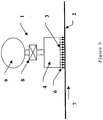
- FIG. 2 there is shown a schematic section view through an embodiment of the steam distributor 1 according to the present invention for delivering steam to the web 2 of a papermaking machine.
- the steam distributor 1 is mounted close to the paper web 2 that is to be steam treated by supports (not shown).
- the arrow 7 shows the machine direction (MD), that is, the moving direction of the web 2.
- the steam distributor 1 comprises a steam housing 4 and a steam inlet 9 that is in sealed communication with the steam housing 4.
- One or several pieces of porous metal plates 3 facing the web 2 at the bottom of the steam distributor 1 form the steam outlets of the housing 4.
- the steam outlets on the porous metal plate 3 are also in sealed communication with the steam housing 4.
- the porous metal plate 3 is placed parallel to the web of the paper sheet.
- the porous metal plate 3 is flat if the steam distributor 1 is mounted above a flat web.
- the porous metal plate 3 can also be formed into a curved metal sheet to match the curvature of the web 2 if the steam distributor 1 is mounted to face a roll.
- Arrow 6 shows the straight streamlines of the steam flow passing through the porous metal plate 3.
- the width of the porous plate 3 in the cross-machine direction defines a band on the web surface that is affected by the steam. This band could cover the whole web surface if a non-profiling steam shower is to be used.
- the width of the band in the CD direction defines the zone size. The size of a single zone can be arbitrary, however 2 inches (about 5 cm) to 6 inches (about 15 cm) are typical for existing profiling steam showers.
- the steam flow rate passing through the steam distributor 1 is determined by several properties of the porous plate 3 as well as the steam pressure in the steam housing 4.
- the influencing properties of the porous metal plate 3 include the length of the porous plate 3 in the machine direction, the media grade and the thickness of the porous plate 3.
- the variety in the selection of the porous metal plate 3 allows the users of the steam distributor 1 to design a steam shower that gives the best fit to their specific application.
- the application could be in the wet end (Location #1 and #2 in Figure 1 ) or in the dry end (Location #3 in Figure 1 , for example), or even in a finishing calender (Location #4 in Figure 1 ) of a paper making machine.
- the steam distributor 1 can deliver controllable steam flow to the web 2 by manipulating the steam pressure in the steam housing 4.
- An actuator valve 8 located between the inlet 9 and the steam housing 4 can be used to provide the required steam pressure in the steam housing 4.
- the inlet 9 is in sealed communication with a pressurized steam source (not shown) that is located off the paper-machine and readily available in any paper mill.
- the web 2 will receive no steam from the steam distributor 1 if the steam pressure in the steam housing 4 is zero. Increasing the steam pressure inside the housing 4 increases the steam flow passing through the porous metal plate 3 and consequently increases the amount of steam received by the moving web 2.
- the porous metal plate 3 can be considered as a conventional screen plate having thousands of thousands of micro-orifices aligned in both the cross-machine direction and the machine direction with spacing in the range of microns. The result is a flat mass or moisture or heat profile within the span (or zone) of the steam distributor.
- the flat steam distribution of the steam distributor 1 benefits all steam shower applications.
- Another benefit of the steam distributor 1 is the minimum coupling between neighboring distributors of a steam shower.
- the minimum coupling is a direct result of the almost perfect square-shaped steam mass profile generated by a single steam distributor 1.
- the result is the highest resolution achievable by a steam shower with a fixed zone size.
- Yet another benefit associated with the minimum coupling of the steam distributor 1 is the insensitivity of the steam distributor's distance to the web or sheet 2.
- Sheet distance is a sensitive parameter for conventional steam showers that require time-consuming on machine fine-tuning at start up. Inappropriate sheet distance of conventional steam showers causes streaking on the surface of the paper.
- the collimated beams of steam delivered by the steam distributor 1 can potentially eliminate the streaking without fine-tuning the sheet distance.
- the pressure drops through a conventional screen plate are less than a couple of kPa (PSI) in unit. Increased pressure drop in the conventional screen plate results in excessive steam velocity and consequently over-spray of the steam.
- PSD kPa
- the porous metal plate 3 of the steam distributor 1 allows the pressure drop to be much larger than that through a conventional screen plate thanks to the added frictions through the micro orifices in the porous plate 3.
- the efficient mixing between environment air and micro steam jets at the porous metal plate 3 during the distribution of the steam may also benefit the increased pressure drop. Larger pressure drops in steam distributor 1 provide a wider control range, as the flow rate passing through the steam distributor 1 is regulated by adjusting the pressure feeding the screen plate or the porous metal plate 3.
- the steam distributor 1 is not limited to the configuration of one porous metal plate 3 per distributor. It is possible to construct a steam shower with steam distributing zones that share a single piece of porous metal plate across the CD direction.
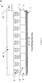
- FIG 3 shows a schematic steam shower 10 that is consisting of an array of the steam distributor 1 of the present invention across the machine direction.
- the steam housings 4 are separated by metal plate 12.
- Each steam distributor 1 has an actuator valve 8 that controls the steam pressure in the corresponding steam housing 4. All the steam distributors 1 share a common steam chamber 18, which is in sealed communication with a steam inlet 14.
- the steam inlet 14 is in sealed communication with a steam source (not shown) off the machine.
- the porous metal plate 3 in Figure 3 can be one single piece across the whole steam shower 10 to reduce the manufacturing and maintenance costs. In this case, sealing between adjacent steam housing 4 may be necessary.
- a porous metal plate 3 in Figure 3 with shapes other than a rectangle could be used to produce a desired mass profile in the CD direction.
- a single steam distributor 1 as shown in Figure 2 with a porous metal plate 3 cut into a special contour along the CD direction according to a measured profile of a selected paper property to be controlled could be used for profiling purposes.
- the measured profile can be a moisture profile, a gloss profile or any other profile that affects the quality of the paper products in the cross-machine direction. In this case, zone actuators and the conventional on-machine profiling are unnecessary. More importantly, a perfect flat moisture profile at the reel could be achieved as this custom designed steam distributor has infinite resolution.
- a variety of other arrangements can be devised which would operate on the same principles disclosed above.
- the steam distributor and the steam shower using the porous metal plate 3 are useful in many other applications.
- the present invention is appropriate where the need exists for a tailorable distribution of a fluid (steam, gas or liquid) to a surface of a medium.
- the distribution could be extremely uniform, or follow a predetermined profile as required.
- porous metal plate using the embodiment of Fig. 2 is a paper suspension device that supports the moving paper web without even touching the surface of the paper. This is especially useful for coated paper.
- element 9 is an inlet for compressed air. Air delivered through the porous metal plate forms a pressurized air cushion between the porous metal plate and the moving web. The air cushion serves as a medium for the contactless support to the moving web.
- FIG. 2 Yet another potential application of the porous metal plate using the embodiment of Fig. 2 is a highly efficient air curtain or air knife.
- Air curtains or air knifes are now widely used with water spray systems in papermaking machine to confine the spraying water droplets to the defined rewet area without causing problems to the papermaking process.
- Air curtains made of porous metal plates can be mounted very close to the moving web without interference to the process. Because the gap between the porous plates and the web sheet can be very small, the air that is required to curtain off water droplets is substantially reduced.
- element 9 is an inlet for compressed air.
Landscapes
- Paper (AREA)
- Nonwoven Fabrics (AREA)
- Treatment Of Fiber Materials (AREA)
Abstract
Claims (11)
- Appareil (1, 10) servant à répartir un fluide, destiné à être utilisé avec une machine qui produit une bande (2), comportant :une enceinte (4);une entrée (9, 18) de fluide en communication étanche avec ladite enceinte (4) ; etune ou plusieurs plaques métalliques (3) montées dans ladite enceinte (4) dans une orientation faisant face à ladite bande (2) lorsque ledit appareil répartiteur (1, 10) de fluide est monté à un emplacement prédéterminé sur ladite machine produisant une bande, ladite ouchacune desdites plaques métalliques (3) formant une pluralité de sorties de fluide qui sont en communication étanche avec ladite enceinte (4) ; etcaractérisé en ce que ladite ou chacune desdites plaques métalliques (3) sont formées d'une poudre métallique qui est comprimée puis frittée de telle sorte que ladite ou chacune desdites plaques métalliques (3) soient poreuses.
- Appareil (1, 10) selon la revendication 1, ladite ou chacune desdites plaques métalliques poreuses (3) étant orientées de façon à être parallèles à ladite bande (2) lorsque ledit appareil (1, 10) est monté sur ladite machine produisant une bande.
- Appareil (1, 10) selon la revendication 1, ladite ou chacune desdites plaques métalliques poreuses (3) présentant un profil qui correspond au profil de ladite bande (2) audit emplacement prédéterminé où ledit appareil (1, 10) est appelé à être monté sur ladite machine produisant une bande.
- Appareil (1, 10) selon la revendication 1, ladite ou chacune desdites plaques métalliques poreuses (3) étant de forme rectangulaire.
- Appareil (1, 10) selon la revendication 1, ladite ou chacune desdites plaques métalliques poreuses (3) étant mises en forme pour donner des tôles métalliques incurvées de façon à épouser la courbure de ladite bande (2) au niveau d'un rouleau d'une machine produisant une bande sur laquelle ledit appareil (1, 10) est monté.
- Appareil (1, 10) selon la revendication 1, comportant en outre une vanne (8) d'actionnement raccordée entre ladite enceinte (4) et ladite entrée (9, 18) de fluide.
- Dispositif de suspension de bande comportant l'appareil (1, 10) selon la revendication 1, le fluide étant de l'air.
- Lame d'air comportant l'appareil (1, 10) selon la revendication 1, le fluide étant de l'air.
- Répartiteur de vapeur comportant l'appareil (1, 10) selon la revendication 1, le fluide étant de la vapeur.
- Diffuseur (10) de vapeur comportant un alignement d'appareils (1) selon la revendication 1.
- Diffuseur (10) de vapeur selon la revendication 10, une chambre (18) à vapeur commune étant en communication étanche avec une entrée (14) de vapeur.
Applications Claiming Priority (5)
| Application Number | Priority Date | Filing Date | Title |
|---|---|---|---|
| US44751803P | 2003-02-14 | 2003-02-14 | |
| US447518P | 2003-02-14 | ||
| US755216 | 2004-01-12 | ||
| US10/755,216 US7452447B2 (en) | 2003-02-14 | 2004-01-12 | Steam distributor for steam showers |
| PCT/EP2004/001100 WO2004072366A1 (fr) | 2003-02-14 | 2004-02-06 | Diffuseur de vapeur pour douches vapeur |
Publications (2)
| Publication Number | Publication Date |
|---|---|
| EP1597429A1 EP1597429A1 (fr) | 2005-11-23 |
| EP1597429B1 true EP1597429B1 (fr) | 2012-05-02 |
Family
ID=32872034
Family Applications (1)
| Application Number | Title | Priority Date | Filing Date |
|---|---|---|---|
| EP04708759A Expired - Lifetime EP1597429B1 (fr) | 2003-02-14 | 2004-02-06 | Diffuseur de fluids |
Country Status (5)
| Country | Link |
|---|---|
| US (1) | US7452447B2 (fr) |
| EP (1) | EP1597429B1 (fr) |
| JP (1) | JP2007524005A (fr) |
| CA (1) | CA2515549C (fr) |
| WO (1) | WO2004072366A1 (fr) |
Families Citing this family (23)
| Publication number | Priority date | Publication date | Assignee | Title |
|---|---|---|---|---|
| US7513975B2 (en) * | 2003-06-25 | 2009-04-07 | Honeywell International Inc. | Cross-direction actuator and control system with adaptive footprint |
| JP4622312B2 (ja) | 2003-08-26 | 2011-02-02 | トヨタ自動車株式会社 | 車両 |
| US9481777B2 (en) | 2012-03-30 | 2016-11-01 | The Procter & Gamble Company | Method of dewatering in a continuous high internal phase emulsion foam forming process |
| US8968517B2 (en) | 2012-08-03 | 2015-03-03 | First Quality Tissue, Llc | Soft through air dried tissue |
| MX2016014887A (es) | 2014-05-16 | 2018-03-01 | First Quality Tissue Llc | Toallita lavable y metodo para formarla. |
| CN104213456B (zh) * | 2014-08-26 | 2016-05-04 | 华南理工大学 | 一种蒸汽箱及调节纸张温湿度的方法 |
| WO2016077594A1 (fr) | 2014-11-12 | 2016-05-19 | First Quality Tissue, Llc | Fibre de cannabis, structures cellulosiques absorbantes contenant de la fibre de cannabis et procédés de fabrication de celles-ci |
| US10273635B2 (en) | 2014-11-24 | 2019-04-30 | First Quality Tissue, Llc | Soft tissue produced using a structured fabric and energy efficient pressing |
| CA2967986C (fr) | 2014-12-05 | 2023-09-19 | Structured I, Llc | Procede de fabrication de courroies pour la fabrication du papier utilisant une technologie d'impression 3d |
| GB201514620D0 (en) * | 2015-08-17 | 2015-09-30 | Landa Labs 2012 Ltd | Air knife |
| US10544547B2 (en) | 2015-10-13 | 2020-01-28 | First Quality Tissue, Llc | Disposable towel produced with large volume surface depressions |
| US10538882B2 (en) | 2015-10-13 | 2020-01-21 | Structured I, Llc | Disposable towel produced with large volume surface depressions |
| US11220394B2 (en) | 2015-10-14 | 2022-01-11 | First Quality Tissue, Llc | Bundled product and system |
| WO2017139786A1 (fr) | 2016-02-11 | 2017-08-17 | Structured I, Llc | Courroie ou tissu comprenant une couche polymère pour machine à papier |
| US20170314206A1 (en) | 2016-04-27 | 2017-11-02 | First Quality Tissue, Llc | Soft, low lint, through air dried tissue and method of forming the same |
| CA3168412C (fr) | 2016-08-26 | 2024-10-22 | Structured I, Llc | Procede de production de structures absorbantes presentant une resistance a l'etat humide, une capacite d'absorption et une souplesse elevees |
| WO2018049390A1 (fr) | 2016-09-12 | 2018-03-15 | Structured I, Llc | Dispositif de formation d'un actif déposé par voie humide utilisant un tissu structuré en tant que fil externe |
| US11583489B2 (en) | 2016-11-18 | 2023-02-21 | First Quality Tissue, Llc | Flushable wipe and method of forming the same |
| CN106978760A (zh) * | 2016-11-30 | 2017-07-25 | 佛山市兴华源机械设备有限公司 | 一种产品加工用的喷淋装置 |
| US10619309B2 (en) | 2017-08-23 | 2020-04-14 | Structured I, Llc | Tissue product made using laser engraved structuring belt |
| DE102018114748A1 (de) | 2018-06-20 | 2019-12-24 | Voith Patent Gmbh | Laminierte Papiermaschinenbespannung |
| US11738927B2 (en) | 2018-06-21 | 2023-08-29 | First Quality Tissue, Llc | Bundled product and system and method for forming the same |
| US11697538B2 (en) | 2018-06-21 | 2023-07-11 | First Quality Tissue, Llc | Bundled product and system and method for forming the same |
Family Cites Families (7)
| Publication number | Priority date | Publication date | Assignee | Title |
|---|---|---|---|---|
| JPS5449606A (en) * | 1977-09-27 | 1979-04-19 | Shimizu Construction Co Ltd | Underground tank with construction of protecting equipment contained |
| ES244837Y (es) | 1979-07-27 | 1980-05-16 | Caja de vapor perfeccionada para calentar una hoja de papel durante su proceso de fabricacion | |
| JPS57171791A (en) * | 1981-04-15 | 1982-10-22 | Mitsubishi Heavy Ind Ltd | Steam supply apparatus |
| JPH09310290A (ja) * | 1996-05-24 | 1997-12-02 | Kubota Corp | 製紙用トップロール装置 |
| FI4283U1 (fi) | 1999-09-06 | 1999-12-31 | Neles Automation Oy | Höyrylaatikko |
| FI110627B (fi) | 2000-04-06 | 2003-02-28 | Metso Paper Automation Oy | Menetelmä höyryn puhaltamiseksi paperirainaa vasten ja paperikoneen höyrylaatikko |
| FI111092B (fi) * | 2001-06-26 | 2003-05-30 | Metso Automation Oy | Menetelmä kuivatuskaasun puhaltamiseksi paperirainaa vasten ja paperikoneen päällepuhalluskuivatin |
-
2004
- 2004-01-12 US US10/755,216 patent/US7452447B2/en not_active Expired - Fee Related
- 2004-02-06 EP EP04708759A patent/EP1597429B1/fr not_active Expired - Lifetime
- 2004-02-06 JP JP2006501756A patent/JP2007524005A/ja active Pending
- 2004-02-06 WO PCT/EP2004/001100 patent/WO2004072366A1/fr not_active Ceased
- 2004-02-06 CA CA2515549A patent/CA2515549C/fr not_active Expired - Fee Related
Also Published As
| Publication number | Publication date |
|---|---|
| WO2004072366A1 (fr) | 2004-08-26 |
| JP2007524005A (ja) | 2007-08-23 |
| CA2515549A1 (fr) | 2004-08-26 |
| CA2515549C (fr) | 2010-05-18 |
| EP1597429A1 (fr) | 2005-11-23 |
| US20040168784A1 (en) | 2004-09-02 |
| US7452447B2 (en) | 2008-11-18 |
Similar Documents
| Publication | Publication Date | Title |
|---|---|---|
| EP1597429B1 (fr) | Diffuseur de fluids | |
| CA1314392C (fr) | Controleur de brillant transversal | |
| EP3096887B1 (fr) | Ensemble buse avec face auto-nettoyante | |
| US6207020B1 (en) | Method for conditioning paper and paperboard webs | |
| EP0380413B1 (fr) | Appareil transversal d'application de vapeur | |
| CA2008733C (fr) | Regulateur d'uni transversal et mode d'utilisation connexe | |
| EP1636419B1 (fr) | Système et méthode pour contrôler les caractéristiques d'une bande de matériau durant sa fabrication dans une machine de fabrication de bandes de matériau | |
| US4763424A (en) | Apparatus and method for the control of web or web-production machine component surface temperatures or for applying a layer of moisture to web | |
| US5045342A (en) | Independent heat moisture control system for gloss optimization | |
| CA1278935C (fr) | Appareil de refroidissement par evaporation et methode de controle de la temperature de surface des rouleaux de papier ou des pieces connexes | |
| JP5334993B2 (ja) | 移動オリフィスを用いてスリット帯状包装紙を作る方法及び装置 | |
| EP2792787B1 (fr) | Méthode et appareil pour distribuer de la vapeur | |
| CA2368330A1 (fr) | Procede pour le conditionnement d'une courroie d'acheminement en feutre | |
| DE112011103033T5 (de) | Luftbalkenanordnung zum Trocknen von Tissue-Papier auf einem Band | |
| US6024797A (en) | Method and apparatus for controlling coat-weight profile | |
| JP4597679B2 (ja) | 水蒸気−水スプレイ・システム | |
| US5711087A (en) | Apparatus for profile control of a sheet having a removable screen | |
| US5798026A (en) | Dry end steam applicator | |
| US3359643A (en) | Production of paper | |
| FI81634C (fi) | Foerfarande och anordning foer avkylning av mantelytan av valsarna i en kalander, speciellt en soft-kalander. |
Legal Events
| Date | Code | Title | Description |
|---|---|---|---|
| PUAI | Public reference made under article 153(3) epc to a published international application that has entered the european phase |
Free format text: ORIGINAL CODE: 0009012 |
|
| 17P | Request for examination filed |
Effective date: 20050914 |
|
| AK | Designated contracting states |
Kind code of ref document: A1 Designated state(s): AT BE BG CH CY CZ DE DK EE ES FI FR GB GR HU IE IT LI LU MC NL PT RO SE SI SK TR |
|
| AX | Request for extension of the european patent |
Extension state: AL LT LV MK |
|
| DAX | Request for extension of the european patent (deleted) | ||
| RBV | Designated contracting states (corrected) |
Designated state(s): DE FI FR SE |
|
| 17Q | First examination report despatched |
Effective date: 20100705 |
|
| GRAP | Despatch of communication of intention to grant a patent |
Free format text: ORIGINAL CODE: EPIDOSNIGR1 |
|
| RTI1 | Title (correction) |
Free format text: FLUID DISTRIBUTOR |
|
| GRAS | Grant fee paid |
Free format text: ORIGINAL CODE: EPIDOSNIGR3 |
|
| GRAA | (expected) grant |
Free format text: ORIGINAL CODE: 0009210 |
|
| AK | Designated contracting states |
Kind code of ref document: B1 Designated state(s): DE FI FR SE |
|
| REG | Reference to a national code |
Ref country code: DE Ref legal event code: R082 Ref document number: 602004037599 Country of ref document: DE Representative=s name: ABB PATENT GMBH, DE |
|
| REG | Reference to a national code |
Ref country code: DE Ref legal event code: R096 Ref document number: 602004037599 Country of ref document: DE Effective date: 20120705 |
|
| REG | Reference to a national code |
Ref country code: SE Ref legal event code: TRGR |
|
| PLBE | No opposition filed within time limit |
Free format text: ORIGINAL CODE: 0009261 |
|
| STAA | Information on the status of an ep patent application or granted ep patent |
Free format text: STATUS: NO OPPOSITION FILED WITHIN TIME LIMIT |
|
| 26N | No opposition filed |
Effective date: 20130205 |
|
| REG | Reference to a national code |
Ref country code: DE Ref legal event code: R097 Ref document number: 602004037599 Country of ref document: DE Effective date: 20130205 |
|
| REG | Reference to a national code |
Ref country code: SE Ref legal event code: EUG |
|
| PG25 | Lapsed in a contracting state [announced via postgrant information from national office to epo] |
Ref country code: FI Free format text: LAPSE BECAUSE OF NON-PAYMENT OF DUE FEES Effective date: 20130206 Ref country code: SE Free format text: LAPSE BECAUSE OF NON-PAYMENT OF DUE FEES Effective date: 20130207 |
|
| REG | Reference to a national code |
Ref country code: FR Ref legal event code: ST Effective date: 20131031 |
|
| REG | Reference to a national code |
Ref country code: DE Ref legal event code: R119 Ref document number: 602004037599 Country of ref document: DE Effective date: 20130903 |
|
| PG25 | Lapsed in a contracting state [announced via postgrant information from national office to epo] |
Ref country code: FR Free format text: LAPSE BECAUSE OF NON-PAYMENT OF DUE FEES Effective date: 20130228 Ref country code: DE Free format text: LAPSE BECAUSE OF NON-PAYMENT OF DUE FEES Effective date: 20130903 |