EP1597510B1 - Fahrzeugsitzsystem mit verbesserter vibrationsisolierung - Google Patents
Fahrzeugsitzsystem mit verbesserter vibrationsisolierung Download PDFInfo
- Publication number
- EP1597510B1 EP1597510B1 EP03716067A EP03716067A EP1597510B1 EP 1597510 B1 EP1597510 B1 EP 1597510B1 EP 03716067 A EP03716067 A EP 03716067A EP 03716067 A EP03716067 A EP 03716067A EP 1597510 B1 EP1597510 B1 EP 1597510B1
- Authority
- EP
- European Patent Office
- Prior art keywords
- frame
- regulator
- gate
- bumper
- top frame
- Prior art date
- Legal status (The legal status is an assumption and is not a legal conclusion. Google has not performed a legal analysis and makes no representation as to the accuracy of the status listed.)
- Expired - Lifetime
Links
- 238000002955 isolation Methods 0.000 title description 15
- 230000033001 locomotion Effects 0.000 claims description 26
- 239000000725 suspension Substances 0.000 claims description 8
- 239000012858 resilient material Substances 0.000 claims description 4
- 230000001105 regulatory effect Effects 0.000 claims 7
- 238000006073 displacement reaction Methods 0.000 description 5
- 230000004044 response Effects 0.000 description 4
- 238000010276 construction Methods 0.000 description 3
- 238000005096 rolling process Methods 0.000 description 3
- 230000001133 acceleration Effects 0.000 description 2
- 230000009471 action Effects 0.000 description 2
- 230000008901 benefit Effects 0.000 description 2
- 239000006096 absorbing agent Substances 0.000 description 1
- 210000003484 anatomy Anatomy 0.000 description 1
- 230000008859 change Effects 0.000 description 1
- 238000006243 chemical reaction Methods 0.000 description 1
- 230000001419 dependent effect Effects 0.000 description 1
- 230000000694 effects Effects 0.000 description 1
- 238000004519 manufacturing process Methods 0.000 description 1
- 238000000034 method Methods 0.000 description 1
- 230000004048 modification Effects 0.000 description 1
- 238000012986 modification Methods 0.000 description 1
- 230000002035 prolonged effect Effects 0.000 description 1
- 230000035939 shock Effects 0.000 description 1
- 210000001835 viscera Anatomy 0.000 description 1
Images



Classifications
-
- B—PERFORMING OPERATIONS; TRANSPORTING
- B60—VEHICLES IN GENERAL
- B60N—SEATS SPECIALLY ADAPTED FOR VEHICLES; VEHICLE PASSENGER ACCOMMODATION NOT OTHERWISE PROVIDED FOR
- B60N2/00—Seats specially adapted for vehicles; Arrangement or mounting of seats in vehicles
- B60N2/50—Seat suspension devices
- B60N2/501—Seat suspension devices actively controlled suspension, e.g. electronic control
-
- B—PERFORMING OPERATIONS; TRANSPORTING
- B60—VEHICLES IN GENERAL
- B60N—SEATS SPECIALLY ADAPTED FOR VEHICLES; VEHICLE PASSENGER ACCOMMODATION NOT OTHERWISE PROVIDED FOR
- B60N2/00—Seats specially adapted for vehicles; Arrangement or mounting of seats in vehicles
- B60N2/02—Seats specially adapted for vehicles; Arrangement or mounting of seats in vehicles the seat or part thereof being movable, e.g. adjustable
- B60N2/04—Seats specially adapted for vehicles; Arrangement or mounting of seats in vehicles the seat or part thereof being movable, e.g. adjustable the whole seat being movable
- B60N2/06—Seats specially adapted for vehicles; Arrangement or mounting of seats in vehicles the seat or part thereof being movable, e.g. adjustable the whole seat being movable slidable
- B60N2/062—Seats specially adapted for vehicles; Arrangement or mounting of seats in vehicles the seat or part thereof being movable, e.g. adjustable the whole seat being movable slidable transversally slidable
-
- B—PERFORMING OPERATIONS; TRANSPORTING
- B60—VEHICLES IN GENERAL
- B60N—SEATS SPECIALLY ADAPTED FOR VEHICLES; VEHICLE PASSENGER ACCOMMODATION NOT OTHERWISE PROVIDED FOR
- B60N2/00—Seats specially adapted for vehicles; Arrangement or mounting of seats in vehicles
- B60N2/50—Seat suspension devices
- B60N2/502—Seat suspension devices attached to the base of the seat
-
- B—PERFORMING OPERATIONS; TRANSPORTING
- B60—VEHICLES IN GENERAL
- B60N—SEATS SPECIALLY ADAPTED FOR VEHICLES; VEHICLE PASSENGER ACCOMMODATION NOT OTHERWISE PROVIDED FOR
- B60N2/00—Seats specially adapted for vehicles; Arrangement or mounting of seats in vehicles
- B60N2/50—Seat suspension devices
- B60N2/505—Adjustable suspension including height adjustment
-
- B—PERFORMING OPERATIONS; TRANSPORTING
- B60—VEHICLES IN GENERAL
- B60N—SEATS SPECIALLY ADAPTED FOR VEHICLES; VEHICLE PASSENGER ACCOMMODATION NOT OTHERWISE PROVIDED FOR
- B60N2/00—Seats specially adapted for vehicles; Arrangement or mounting of seats in vehicles
- B60N2/50—Seat suspension devices
- B60N2/506—Seat guided by rods
- B60N2/508—Scissors-like structure
-
- B—PERFORMING OPERATIONS; TRANSPORTING
- B60—VEHICLES IN GENERAL
- B60N—SEATS SPECIALLY ADAPTED FOR VEHICLES; VEHICLE PASSENGER ACCOMMODATION NOT OTHERWISE PROVIDED FOR
- B60N2/00—Seats specially adapted for vehicles; Arrangement or mounting of seats in vehicles
- B60N2/50—Seat suspension devices
- B60N2/509—Seat guided by slides or the like
-
- B—PERFORMING OPERATIONS; TRANSPORTING
- B60—VEHICLES IN GENERAL
- B60N—SEATS SPECIALLY ADAPTED FOR VEHICLES; VEHICLE PASSENGER ACCOMMODATION NOT OTHERWISE PROVIDED FOR
- B60N2/00—Seats specially adapted for vehicles; Arrangement or mounting of seats in vehicles
- B60N2/50—Seat suspension devices
- B60N2/52—Seat suspension devices using fluid means
- B60N2/525—Seat suspension devices using fluid means using gas
-
- B—PERFORMING OPERATIONS; TRANSPORTING
- B60—VEHICLES IN GENERAL
- B60N—SEATS SPECIALLY ADAPTED FOR VEHICLES; VEHICLE PASSENGER ACCOMMODATION NOT OTHERWISE PROVIDED FOR
- B60N2/00—Seats specially adapted for vehicles; Arrangement or mounting of seats in vehicles
- B60N2/50—Seat suspension devices
- B60N2/54—Seat suspension devices using mechanical springs
- B60N2/544—Compression or tension springs
Definitions
- the present invention pertains to vehicle seats and in particular to vehicle seating arrangements which isolate passengers from vibrations carried through the vehicle structure.
- the goal of ameliorating systems is to selectively absorb vibrational energy and to channel or dissipate the unwanted energy away from the driver's anatomy.
- vibrations arriving at a driver's seat bear directional characteristics, and improvements to seating designs take advantage of this fact by restricting seating improvements to a particular type of vibration problem.
- seating improvements have been directed to improvements in providing fore and aft isolation and vertical isolation. By focusing isolation systems in this manner, it is hoped that the size of the isolation systems will not be so large as to require modification of the vehicle, due to increased height under a passenger's seat, for example.
- US 5,957,426 relates to a mechanical seat suspension between upper and lower supports comprising a scissors arm linkage and a support pivot assembly allowing height adjustment to multiple positions, corresponding to the preamble of claim 1.
- US 4,659,052 relates to a weight adjustment support device for a vehicle seat which is capable for adjusting the cushioning property of the seat according to weights or taste of an occupant.
- US 6,135,412 relates to a universal seat assembly for a garden tractor comprising a base for attachment to the vehicle, the base including an axle to which a first.support plate is pivotally mounted.
- Another object of the present invention is to provide improvements in the amount of isolation, using inexpensive components and cost-effective fabrication techniques.
- a further object of the present invention is to provide a user-selectable control over the fore and aft motion of the seating system.
- Yet another object of the present invention is to provide automatic adjustment of fore and aft motion control and vertical motion control proportional to the weight of the driver.
- a vehicle seating system is generally indicated at 10. Included is a linking system or middle frame 12 movably connecting a top frame 14 to a bottom frame 16. Bottom frame 16 has portions 20 for conventional fastening to a vehicle. Top frame 14 has portions 22 for fixed connection to a vehicle seat.
- the vehicle seating system10 isolates a driver or other passenger from vibrations which would otherwise be transmitted through the vehicle to the vehicle occupants.
- the vehicle seating system 10 provides fore/aft isolation for those occupants seated atop the vehicle seating system. It has been recognized that occupants subjected to fore/aft vibrations for prolonged periods of time suffer from more than a mere annoyance. With prolonged exposure to fore/aft vibrations, occupants tend to become more quickly fatigued because of the tendency of the human body to resist the effects of such vibrations. Over years of exposure to vibrations of this type, vehicle occupants may experience trouble in their joints and internal organs, for example. Various systems have been proposed in the past to provide fore/aft isolation.
- the present invention provides fore/aft isolation which is proportional to an occupant's weight and which therefore reliably provides a desired, effective reaction to fore/aft vibrations.
- the middle frame 12 includes two pairs of scissored arms, one pair of arms 30, 32 on the port or left side of the middle frame (see FIG. 1 ) and another pair of arms 34, 36 on the starboard or right-hand side of the middle frame as can be seen for example in FIG. 4 .
- Each scissor arm has opposed ends and it is preferred that rollers be mounted to each end of the scissor arms. Referring to FIG. 1 , for example, four rollers are provided at the forward end 40 of the seating assembly and four rollers are provided at the rear end 42 (see FIG. 6 ). Rollers 30F and 30A are visible in FIGS. 2 and 4 , and rollers 32F and 32A are visible in FIGS. 4 and 1 , respectively. Rollers 34F, 34A are visible in FIGS. 1 and 4 , respectively, and rollers 36F, 36A are visible in FIGS. 1 and 3 , respectively.
- relatively straight guide tracks are provided for rollers at the forward end 40 of the seating assembly.
- frame 14 provides straight or linear guide tracks 14A, 14B for rollers 32F, 34F at the left and right sides, respectively.
- Bottom frame 16 includes straight or linear guide tracks 16A, 16B for rollers 30F, 36F at the left and right sides, respectively.
- bottom frame 16 includes sockets 16C, 16D for pivotal connection to rollers 32A, 34A at the left and right sides, respectively.
- Sockets 16C, 16D provide pivotal connection of the aft ends of scissor arms 32, 34, respectively.
- Roller and socket combinations are preferred for their smooth operating characteristics. However, if desired, other conventional pivotal connections could be employed.
- the remaining pair of rollers at the aft, upper ends of the seating assembly are mounted in curvilinear guide tracks 14C, 14D at the left and right sides, respectively.
- the curvilinear tracks are sometimes referred to as "cups.”
- the curvilinear guide tracks 14C, 14D are convex when viewed from above and concave when viewed from below.
- the curvilinear guide tracks are preferably formed with an upper curvilinear guide wall 60 and a lower curvilinear guide wall 62. As can be seen for example in FIGS.
- the curvilinear guide walls have common centers so as to provide a relatively close fit rolling captivity for the rollers traveling therein to provide a smooth gliding motion, as is preferred in carrying out the present invention.
- the weight of the seat occupant will produce a downward force on the vehicle seating system.
- the downward force will be applied on upper curvilinear guide wall 60 which is transferred to roller 36A, producing increased rolling resistance compared to a "no-load" condition.
- roller 36A is free to travel back and forth along the cup or curvilinear guide track, greater rolling resistance will be experienced with heavier seat occupants, and thus the response time will be proportionally slower for heavier occupants.
- an air spring 70 is held captive between deck portions 72, 74 of the upper and lower frames 14, 16, respectively. If desired, the air spring 70 could be replaced by conventional mechanical suspensions. However, the use of an air spring suspension is preferred because its natural frequency can be held more constant and automatic adjustments (by altering the internal pressure of the air spring) can be made to accommodate occupants of different weights.
- a dash pot or shock absorber type device 80 is pinned at one end to a cross member 82 spanning the forward ends of scissor arms 30, 36. Referring to FIG. 1 , the remaining free end of dash pot 80 is pinned at 86 to the pivotal connection of scissor arms 34, 36.
- upper frame 14 has a generally rectangular shape when viewed from above, with cross member 102 connecting linear guide tracks 14A, 14B and cross member 104 connecting cups or curvilinear guide tracks 14C, 14D.
- the lower frame 16 has members cooperating to form a six sided rectangular box with open walls. As can be seen in FIG.
- frame 16 includes a transverse member 110 spanning linear guide tracks 16A, 16B and, with reference to FIG. 3 frame 16 at its upper, after end has a cross member 112 connecting guide sockets 16C,16D.
- the deck 74 supporting the bottom end of air spring 70 spans the cross members 110, 112.
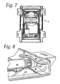
- roller 36A is supported on a shaft 120.
- Shaft 120 may be pivotally supported at the right-hand end of cross member 92 as seen in FIG. 8 .
- cross member 92 is preferably provided as a web member spanning the distance between rollers 36A, 30A. If desired, to achieve advantages explained herein, shaft 120 (see FIG. 8 ) could be made to span the distance between rollers 36A, 30A so as to provide continuous support for the rollers at the aft end of the upper frame 14.
- upper frame 14 freely reciprocates back and forth in a generally horizontal direction except for a slight vertical excursion that the upper aft end imparted by operation of cups or curvilinear guide tracks 14C, 14D.
- pairs of scissor arms be glidingly supported by a single pair of cups or curvilinear tracks, a single pair of pivotal connections and two pairs of linear guide tracks located at the forward end of the vehicle seating system.
- the scissor arms employed can take virtually any conventional shape including the straight scissor arm shaped visible for example in FIG.
- dash pot 80 described above could be located at other portions of the vehicle seating assembly.
- dash pot 80 is connected between the upper end of frame 16 and the forward end of scissor arm 34.
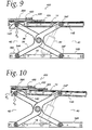
- roller 36A is located at a midpoint of cup or curvilinear guide track 14D.
- a downward force is imparted to the upper end of the roller through the upper guide wall of the cup.
- Downward force components carried by the aft end of scissor arm 36 is transmitted through the bottom of roller to the bottom curvilinear wall of cup 14D.
- FIG. 10 shows the resulting operation caused by a forward acceleration of the vehicle, causing the roller 36A to move to the left or rearward extent of cup 14D.
- FIG. 10 shows the resulting operation caused by a forward acceleration of the vehicle, causing the roller 36A to move to the left or rearward extent of cup 14D.
- roller 36A moves to the forward end of cup 14D in response to a rearwardly directed acceleration imparted by the vehicle to the lower, fixedly mounted frame 16.
- upper movable 14 frame follows the displacement of roller 36A which supports the frame.
- upper movable frame 14 reciprocates back and forth, in force-dissipating response.
- the dynamic fore/aft properties of the system can be adjusted.
- the radius of curvature of the cups may be altered in different systems to provide a desired natural frequency for fore/aft motion.
- the radius of curvature also determines the force deflection characteristic, or effective spring rate, for fore/aft motion.
- the effective spring rate is fairly constant for a given radius of curvature with slight variations for different displacements in the fore-aft direction.
- the natural frequency of fore/aft isolator is in the range of 0.60 to 1.20 Hertz for the effective isolation of fore/aft motions typical of commercial vehicles.
- the radius of curvature of the cups is set to approximately 13.60 inches, resulting in an effective spring rate of about 7.40 Ibs/inch.
- the radius of curvature of the cups is set to approximately 3.40 inches, resulting in an effective spring rate of roughly 30.00 Ibs/inch.
- the most preferred natural frequency for fore/aft motion is 1.00 Hertz. This frequency corresponds roughly to a radius of curvature of 5.00 inches and an effective spring rate of 20.00 Ibs/inch.
- the dynamic vertical motion properties of the system can also be adjusted.
- the internal pressure of air spring 70 automatically adjusts to the change in weight (w) associated with different occupants.
- the natural frequency of vertical motion is in the range of 0.50 to 1.20 Hertz for the effective isolation of vertical motions typical of commercial vehicles.
- the spring rate is set to about 5.11 Ibs/inch.
- the spring rate is set to about 30.00 Ibs/inch.
- the most preferred natural frequency of vertical motion is 0.70 Hertz. This natural frequency of vertical motion corresponds to a spring rate of 10.00 Ibs/inch.
- shaft 120 extends the width of the upper frame part 14, from roller 30A (see FIG. 13 ) to roller 36A (see FIG. 8 ).
- a shuttle 170 has a hole 172 for receiving shaft 120 and is free to rotate about the shaft.
- a bumper 176 having fore and aft surfaces 178, 180 is mounted atop shuttle 170. Bumper 176 is preferably made of rubber or other resilient material. Less preferably, the bumper could be made of non-resilient material.
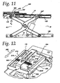
- a slide assembly or fore/aft regulator system 200 is provided at the aft end of the vehicle seating assembly and is positioned atop upper frame 14.
- Fore/aft regulator system 200 includes a slide frame 202 which is fixed in position, and a gate 204 mounted for lateral reciprocation within frame 202, in a direction of arrow 208 shown in FIG. 12 .
- Gate 204 is coupled to a spring carrier 212 through a vector pair of selector springs 216, 218 which are, in turn, secured to gate 204 by pins 220, 222, respectively.
- gate 204 has a stepped opening 230 with step portions 230A, 230B and 230C arranged sequentially in increasing size.
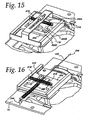
- a cable 234, connected to spring carrier 212 applies tension to a return spring 238. Tension is applied in the direction of arrow 242 in FIG. 16 . This imparts a force to gate 204 through selector springs 216, 218 which urges the gate in a direction of arrow 242, moving the gate with respect to bumper 176.
- gate 204 is urged from the position shown in FIG. 14 (with bumper 176 in gate opening 230A) to the position shown in FIG. 15 , (with the bumper located in the larger gate opening 230C).
- force is applied to spring carrier 212 in the direction of arrow 240, causing spring carrier 212 to distort the selector springs 216, 218 in the manner indicated in FIG. 14 .
- spring force is applied to gate 204 to move the gate in the direction of arrow 240.
- the vector spring system 216, 218 limits the amount of maximum force that the cable has to overcome, (so that the cable does not have to overcome the locking force of the gate against the bumper).
- the gate 204 assumes the position shown in FIG. 15 with the selector springs 216, 218 achieving a relaxed position, as indicated.
- return spring 238 is secured at one end to spring carrier 212 and at the other end to a securement 244 on upper frame 14.
- the selector spring 238 limits the amount of tension which can be applied to the system by cable 234.
- cable 234 is terminated by a detented user engageable adjustment handle of conventional construction allowing displacement of the cable by three different amounts corresponding to the stepped openings in gate 204.
- the first stepped opening 230A is dimensioned for close engagement with bumper 176 as shown for example in FIGS. 12 , 14 and 16 .
- the selector springs provide a vector spring system which, with operation of cable 234 urges gate 204 to bring gate stepped openings of increased size about bumper 176.
- bumper 176 is allowed the greatest range of travel within stepped slot 230C.
- Step 230B provides an intermediate position allowing the bumper an intermediate range of travel.
- Three stepped openings are shown in the figures. However, more or less stepped openings can be provided, as desired and such is contemplated by the present invention.
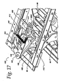
- FIG. 17 an alternative arrangement of a fore/aft regulator system, is generally indicated at 400.
- the slide frame has been eliminated, and the sliding gate has been replaced with a pivoting gate indicated at 404.
- Gate 404 includes a stepped opening 406 with stepped slots 406A, 406B and 406C.
- Bumper 176 is mounted to a carriage 410 which includes drive links 412 connected to axle or shaft 120.
- An operator 420 is pivotally connected at 424 along with gate 404 to cross member 426.
- the return springs 430, 432 are connected to the free end of operator arm 434. The remaining end of return spring 432 is supported by pin 438 coupled to gate 404.
Landscapes
- Engineering & Computer Science (AREA)
- Aviation & Aerospace Engineering (AREA)
- Transportation (AREA)
- Mechanical Engineering (AREA)
- Seats For Vehicles (AREA)
- Springs (AREA)
- Combined Devices Of Dampers And Springs (AREA)
- Vibration Prevention Devices (AREA)
Claims (29)
- Fahrzeugsitzsystem (10) zum Abstützen eines Fahrzeugsitzes in einem Fahrzeug umfassend:einen oberen Rahmen (14) mit einer oberen Anbringvorrichtung zum Sichern an dem Fahrzeugsitz;einen unteren Rahmen (16) mit einer unteren Anbringvorrichtung zum Sichern an dem Fahrzeug;ein Verbindungssystem (12) zum beweglichen Anbringen des oberen Rahmens an dem unteren Rahmen, wobei das Verbindungssystem Paare drehbar miteinander verbundene Scherenarme (30, 32, 34, 36), die an gegenüberliegenden Seiten des oberen und unteren Rahmens angeordnet sind umfasst;gekennzeichnet, durchden oberen Rahmen mit vorderen (40) und hinteren Enden, die zwischen gegenüberliegenden Seiten angeordnet sind, und vier Ecken mit einer Rollenlaufbahn (14A, 14B, 14C, 14D) an jeder Ecke;den unteren Rahmen mit vorderen und hinteren Enden, die zwischen gegenüberliegenden Seiten angeordnet sind, und vier Ecken mit einer Rollenlaufbahn (16A, 16B) an jeder vorderen Ecke und einer Fassung (16C, 16D) an jeder hinteren Ecke;von den Enden der Scherenarme der Verbindungssystems getragenen Rollen (30A, 30F, 32A, 34A, 34F, 36A, 36F) undim Allgemeinen kurvenförmige Rollenbahnen (14C, 14D) an dem hinteren Ende des oberen Rahmens, um die darin beinhalteten Rollen (30A, 36A) auf eine kurvenförmige Bewegung zu beschränken, wobei die Fassungen (16C, 16D) am hinteren Ende des unteren Rahmens die darin angeordneten Rollen (32A, 34A) drehbar halten und die verbleibenden Rollenlaufbahnen (14A, 14B, 16A, 16B) im Allgemeinen gerade sind, um die darin angeordneten Rollen (30F, 32F, 34F, 36F) auf eine im Allgemeinen geradlinige Bewegung zu beschränken.
- System nach Anspruch 1, bei dem die kurvenförmigen Bahnen, wenn von oben betrachtet, im Allgemeinen konvex sind.
- System nach Anspruch 1, ferner aufweisend einen doppelseitigen Vibrationsdämpfer (80), der an einem Ende mit dem Verbindungssystem verbunden ist.
- System nach Anspruch 3, ferner aufweisend eine Querstrebe (82), die sich zwischen den vorderen Enden der Scherenarme erstreckt und wobei der doppelseitige Vibrationsdämpfer mit einem Ende an die Querstrebe gestiftet ist und mit einem zweiten Ende an die Drehverbindung eines Paar Scherenarme gestiftet ist.
- System nach Anspruch 1, ferner aufweisend eine Luftfederaufhängung (70), die zwischen dem oberen Rahmen und dem unteren Rahmen angeordnet ist.
- System nach Anspruch 1, bei dem die im Allgemeinen kurvenförmigen Rollenbahnen einen vorgegebenen Kurvenradius aufweisen, der ausgewählt ist um die vorwärts/rückwärts Bewegung in dem Frequenzbereich von 0,60 Hertz bis 1,20 Hertz zu isolieren.
- System nach Anspruch 1, ferner aufweisend eine mechanische Aufhängung, die sich zwischen dem oberen Rahmen und dem unteren Rahmen erstreckt, wobei die mechanische Aufhängung eine Federrate, die auswählt ist um die vertikale Bewegung im Frequenzbereich von 0,50 Hertz bis 1,20 Hertz zu isolieren, aufweist.
- System nach Anspruch 1, ferner aufweisend ein Regulierungssystem (200) zum Regulieren des Betrages der Vorwärts- und Rückwärtsbewegung des oberen Rahmens, wobei das Regulierungssystem umfasst:einen Regulierrahmen (202), der von dem oberen Rahmen getragen wird,einen Schieber (204), der von dem Regulierrahmen getragen wird und eine Öffnung aufweist, die innere abgestufte Einstelloberflächen festlegt;eine Achse (120), die die Rollen an dem hinteren Ende des oberen Rahmens verbindet;eine Pendelvorrichtung (170), die zur Bewegung entlang der Achse angebracht ist;einen Stoßfänger (176), der auf der Pendelvorrichtung angebracht ist und vordere und hintere Kontaktierungsoberflächen aufweist;wobei der Stoßfänger innerhalb der Öffnung, die durch den Schieber festgelegt wird, angeordnet ist; undeine Auswählanordnung (216, 218) zum Bewegen des Schiebers in Bezug auf den Stoßfänger, um eine innere abgestufte Einstelloberfläche in Bezug auf den Stoßfänger auszurichten.
- System nach Anspruch 8, bei dem der Stoßfänger eine äußere elastische Oberfläche aufweist.
- System nach Anspruch 9, bei dem der Stoßfänger aus elastischem Material hergestellt ist.
- System nach Anspruch 8, ferner aufweisend eine gekerbte Führung die sich über die Breite des Regulierrahmes erstreckt, wobei die Auswählvorrichtung eine Gleitvorrichtung (212), die gleitbar in der gekerbten Führung angeordnet ist, ein Paar doppelseitiger Federn (216, 218), die mit ersten Enden mit der Gleitvorrichtung und mit zweiten Enden mit den beabstandeten Abschnitten des Schiebers verbunden sind und eine Gleitvorrichtungsbewegungsanordnung, die mit der Gleitvorrichtung verbunden ist um die Gleitvorrichtung entlang der gekerbten Führung zu bewegen, umfasst.
- System nach Anspruch 11, bei dem die Gleitvorrichtungsbewegungsanordnung ein Kabel (234) umfasst, das mit einem ersten Ende an der Gleitvorrichtung befestigt ist, wobei der Regulierrahmen ferner eine Rückstellfeder (238), die mit einem ersten Ende mit der Gleitvorrichtung verbunden ist und mit einem zweiten Ende mit dem Regulierrahmen verbunden ist, um die Gleitvorrichtung in eine erste Richtung zu drängen, um einem von dem Kabel angewendeten Zug standzuhalten, umfasst.
- System nach Anspruch 1, bei dem das Verbindungssystem ferner ein Verbindungsrahmentragewerk (90, 92, 72), das die Enden der Scherenarme verbindet, aufweist und das System ferner einen Reguliermechanismus (200) zum Regulieren des Betrags an Vorwärts- und Rückwärtsbewegung des oberen Rahmens umfasst, wobei der Reguliermechanismus umfasst:einen Regulierrahmen (202), der von dem oberen Rahmen getragen wird,einen Schieber (204), der von dem Regulierrahmen getragen wird und eine Öffnung aufweist, die innere Schritteinstelloberflächen festlegt;eine Pendelvorrichtung (170), die von dem Verbindungsrahmentragewerk getragen wird;einen Stoßfänger (176), der auf der Pendelvorrichtung angebracht ist und vordere und hintere Kontaktierungsoberflächen aufweist;wobei der Stoßfänger innerhalb der Öffnung, die durch den Schieber festgelegt wird, angeordnet ist; undeine Auswählanordnung (216, 218) zum Bewegen des Schiebers in Bezug auf den Stoßfänger, um eine innere abgestufte Einstelloberfläche in Bezug auf den Stoßfänger auszurichten, wodurch selektiv die Vorwärts- und Rückwärtsbewegung des Schiebers in Bezug auf den Stoßfänger begrenzt wird.
- System nach Anspruch 1, ferner aufweisend eine Achse (120), die die Rollen an dem hinteren Ende des oberen Rahmens verbindet.
- System nach Anspruch 1, ferner aufweisend Verbindungsabschnitte des Verbindungsrahmentragewerks (92) der Scherenarme an dem hinteren Ende des oberen Rahmens.
- System nach Anspruch 15, ferner aufweisend einen Regulierungsmechanismus (400) zum Regulieren des Betrags an Vorwärts- und Rückwärtsbewegung des oberen Rahmens, wobei das Regulierungssystem umfasst:einen Regulierungsrahmen (412), der von dem oberen Rahmen getragen wird,einen Schieber (404), der drehbar mit dem Regulierrahmen verbunden ist und eine Öffnung aufweist, die die inneren gestuften Einstelloberflächen festlegt;einen Stoßfänger (176), der auf dem Regulierrahmen angeordnet ist und vordere und hintere Kontaktierungsoberflächen aufweist, wobei der Stoßfänger innerhalb der von dem Schieber festgelegten Öffnung angeordnet ist; undeine Auswählanordnung (430, 432) zum drehbaren Bewegen des Schiebers in Bezug auf den Stoßfänger, um eine innere abgestufte Einstelloberfläche in Bezug auf den Stoßfänger auszurichten.
- System nach Anspruch 16, bei dem die Auswählanordnung einen V-förmigen Bedienhebel (420), der drehbar mit dem Regulierrahmen verbunden ist, umfasst;
wobei ein Ende des Bedienhebels mit einem Kabel (234) verbunden ist, das andere Ende des Bedienhebels mit dem Schieber durch eine erste Feder (432) verbunden ist und mit dem Regulierrahmen durch eine zweite Feder (430) verbunden ist, wobei die erste und zweite Feder den von dem Kabel auf den Bediener angelegten Zugkräften entgegenwirken. - System nach Anspruch 1, ferner aufweisend ein Reguliersystem (200) zum Regulieren des Betrags an Vorwärts- und Rückwärtsbewegung des oberen Rahmens, wobei das Reguliersystem umfasst:einen Regulierrahmen (202), der von dem oberen Rahmen getragen wird,einen Schieber (204), der von dem Regulierrahmen getragen wird und der eine Öffnung mit inneren abgestuften Einstelloberflächen festlegt;eine Achse (120), die die Rollen an entweder dem hinteren Ende oder dem vorderen Ende des oberen Rahmens verbindet;eine Pendelvorrichtung (170), die zur Bewegung entlang der Achse angebracht ist;wobei die Pendelvorrichtung innerhalb der von dem Schieber festgelegten Öffnung angeordnet ist; undein erster Aktuator (212) mit dem Schieber verbunden ist, um den Schieber in Bezug auf die Pendelvorrichtung schieben, um eine andere innere abgestufte Einstelloberfläche in Bezug auf die Pendelvorrichtung auszurichten.
- System nach Anspruch 18, bei dem zumindest ein Abschnitt der Pendelvorrichtung eine äußere elastische Oberfläche aufweist.
- System nach Anspruch 18, bei dem die Pendelvorrichtung ferner einen Stoßfänger (176) mit Kontaktoberflächen aufweist und der Stoßfänger innerhalb der von dem Schieber festgelegten Öffnung angeordnet ist.
- System nach Anspruch 20, bei dem der Stoßfänger aus elastischem Material hergestellt ist.
- System nach Anspruch 18, ferner aufweisend eine gekerbte Führung, die sich entlang des Regulierrahmes erstreckt, wobei der erste Aktuator eine Gleitvorrichtung, die gleitbar in der gekerbten Führung angeordnet ist, ein erstes Vorspannelement (216), das die Gleitvorrichtung und den Schieber verbindet und einen zweiten Aktuator, der mit der Gleitvorrichtung verbunden ist, um die Gleitvorrichtung entlang der gekerbten Führung zu bewegen, aufweist.
- System nach Anspruch 22, bei dem der zweite Aktuator (234) ein erstes Ende, das mit der Gleitvorrichtung verbunden ist, aufweist, wobei das Reguliersystem ferner ein zweites Vorspannelement (218) mit einem ersten Ende, das mit der Gleitvorrichtung verbunden ist, und mit einen zweiten Ende, das mit dem oberen Rahmen verbunden ist, um der von dem zweiten Aktuator verursachten Bewegung entgegenzuwirken, aufweist.
- System nach Anspruch 1, bei dem das Verbindungssystem ferner einen Reguliermechanismus (200) zum Regulieren des Betrags an Vorwärts- und Rückwärtsbewegung des oberen Rahmens aufweist, wobei der Regulierungsmechanismus umfasst:einen Regulierrahmen (202), der von dem oberen Rahmen getragen wird,einen Schieber (204), der von dem Regulierrahmen getragen wird und der eine Öffnung mit inneren abgestuften Einstelloberflächen festlegt;eine Pendelvorrichtung (170), die entlang einem der Scherenarme beweglich ist;einen Stoßfänger (176), der auf der Pendelvorrichtung angebracht ist und vordere und hintere Kontaktierungsoberflächen aufweist;wobei der Stoßfänger innerhalb der Öffnung, die durch den Schieber festgelegt wird angeordnet ist; undein Aktuator zum Bewegen des Schiebers in Bezug auf den Stoßfänger ausgebildet ist, um eine ausgewählte innere abgestufte Einstelloberfläche in Bezug auf den Stoßfänger auszurichten, wodurch selektiv die Vorwärts- und Rückwärtsbewegung des Schiebers in Bezug auf den Stoßfänger eingestellt wird.
- System nach Anspruch 1, ferner aufweisend einen Reguliermechanismus (400) zum Regulieren des Betrags an Vorwärts- und Rückwärtsbewegung des oberen Rahmens, wobei der Reguliermechanismus umfasst:einen Regulierungsrahmen (412), der von dem oberen Rahmen getragen wird,einen Schieber (404), der drehbar mit dem Regulierrahmen verbunden ist und eine Öffnung mit inneren gestuften Einstelloberflächen festlegt;einen Anschlag (176), der auf dem Regulierrahmen angeordnet ist und vordere und hintere Kontaktierungsoberflächen aufweist, wobei der Anschlag innerhalb der von dem Schieber festgelegten Öffnung angeordnet ist; undeinen Aktuator (234) zum drehbaren Bewegen des Schiebers in Bezug auf den Anschlag, um unterschiedliche innere abgestufte Einstelloberflächen in Bezug auf den Anschlag auszurichten.
- System nach Anspruch 25, bei dem der Aktuator einen im Allgemeinen V-förmigen Arm (420) umfasst, der drehbar mit dem Regulierrahmen verbunden ist; und
ein Kabel (234), das an einem Ende des Arms angeordnet ist, wobei das andere Ende des Bedieners mit dem Schieber und dem Regulierrahmen an zumindest einer ersten Feder (432) verbunden ist, wobei die zumindest eine Feder einem von dem Kabel an den Arm angelegten Zug entgegenwirkt. - System nach Anspruch 1, ferner aufweisend ein Regulierungssystem (200, 400) zum Regulieren des Betrags an Vorwärts- und Rückwärtsbewegung des oberen Rahmens.
- System nach Anspruch 27, bei dem das Regulierungssystem zwischen einer und mehreren Positionen einstellbar ist, wobei eine Position im Wesentlichen die Vorwärts- und Rückwärtsbewegung des oberen Rahmens verhindert und die andere oder die weiteren Positionen einen vorgegebenen begrenzten Betrag an Vorwärts- und Rückwärtsbewegung des oberen Rahmens erlauben.
- System nach Anspruch 27, bei dem das Reguliersystem umfasst:einen Begrenzungsmechanismus (230A), um im Wesentlichen die Vorwärts- und Rückwärtsbewegung des oberen Rahmens wenn das Reguliersystem in einer ersten Position ist zu verhindern;einen Stoßfänger (176) der zwischen zwei Anschlägen (230B, 230C) beweglich ist, um den Betrag an Vorwärts- und Rückwärtsbewegung des oberen Rahmens wenn das Reguliersystem in einer zweiten Position ist zu begrenzen undeine Auswählanordnung (238) zum Auswählen zwischen der ersten und zweiten Position.
Applications Claiming Priority (3)
| Application Number | Priority Date | Filing Date | Title |
|---|---|---|---|
| US369357 | 1995-01-06 | ||
| US10/369,357 US6866236B2 (en) | 2003-02-18 | 2003-02-18 | Vehicle seating system with improved vibration isolation |
| PCT/US2003/004841 WO2004074735A1 (en) | 2003-02-18 | 2003-02-19 | Vehicle seating system with improved vibration isolation |
Publications (3)
| Publication Number | Publication Date |
|---|---|
| EP1597510A1 EP1597510A1 (de) | 2005-11-23 |
| EP1597510A4 EP1597510A4 (de) | 2007-10-31 |
| EP1597510B1 true EP1597510B1 (de) | 2011-06-22 |
Family
ID=44257186
Family Applications (1)
| Application Number | Title | Priority Date | Filing Date |
|---|---|---|---|
| EP03716067A Expired - Lifetime EP1597510B1 (de) | 2003-02-18 | 2003-02-19 | Fahrzeugsitzsystem mit verbesserter vibrationsisolierung |
Country Status (3)
| Country | Link |
|---|---|
| EP (1) | EP1597510B1 (de) |
| AT (1) | ATE514030T1 (de) |
| CA (1) | CA2515781C (de) |
Families Citing this family (4)
| Publication number | Priority date | Publication date | Assignee | Title |
|---|---|---|---|---|
| CN114604149B (zh) * | 2022-03-22 | 2023-09-26 | 上海三一重机股份有限公司 | 座椅减振系统、座椅及作业机械 |
| CN115574219B (zh) * | 2022-11-01 | 2025-07-29 | 洛阳国兴光电科技有限公司 | 一种移动载体精密仪器隔振系统 |
| US12600278B2 (en) * | 2023-12-19 | 2026-04-14 | Volvo Car Corporation | Vehicle seat floor filler |
| CN118328272A (zh) * | 2024-06-12 | 2024-07-12 | 广州市森锐科技股份有限公司 | 一种摄像头机械防抖结构 |
Family Cites Families (6)
| Publication number | Priority date | Publication date | Assignee | Title |
|---|---|---|---|---|
| FR2470024A1 (fr) * | 1979-11-27 | 1981-05-29 | Sable Freres Int | Support de siege de vehicule avec dispositif incorpore d'amortissement des accelerations longitudinales |
| US4455009A (en) * | 1982-05-10 | 1984-06-19 | Sears Manufacturing Co., Inc. | Adjustable vehicle seat mounting device |
| JPS61128140U (de) * | 1985-01-31 | 1986-08-11 | ||
| DE3826829A1 (de) * | 1988-08-06 | 1990-02-08 | Tachi S Co | Aufhaengung fuer einen fahrzeugsitz |
| US5957426A (en) * | 1997-04-10 | 1999-09-28 | Brodersen; Cole T. | Mechanical seat suspension with multiple position, lift-type height adjuster |
| US6135412A (en) * | 1999-05-12 | 2000-10-24 | Buehler; Richard B. | Universal seat assembly for garden tractor |
-
2003
- 2003-02-19 AT AT03716067T patent/ATE514030T1/de not_active IP Right Cessation
- 2003-02-19 CA CA002515781A patent/CA2515781C/en not_active Expired - Fee Related
- 2003-02-19 EP EP03716067A patent/EP1597510B1/de not_active Expired - Lifetime
Also Published As
| Publication number | Publication date |
|---|---|
| ATE514030T1 (de) | 2011-07-15 |
| EP1597510A4 (de) | 2007-10-31 |
| CA2515781A1 (en) | 2004-09-02 |
| CA2515781C (en) | 2009-10-20 |
| EP1597510A1 (de) | 2005-11-23 |
Similar Documents
| Publication | Publication Date | Title |
|---|---|---|
| US6866236B2 (en) | Vehicle seating system with improved vibration isolation | |
| EP1373014B1 (de) | Sitzaufhängung | |
| US5251864A (en) | Suspension device for vehicle seat | |
| US4687250A (en) | Adjustable seat assembly for vehicle | |
| EP0873905B1 (de) | Verstellbare Fahrzeugsitzaufhängung | |
| CA2037945C (en) | Seat suspension with cam support member and spring assisted height adjustment | |
| EP1050428B1 (de) | Verstellbare Abfederung des ganzen Sitzes | |
| US3599232A (en) | Vehicle seat suspension system | |
| EP0787621A2 (de) | Verstellbare Fahrzeugsitzaufhängung | |
| US7168671B2 (en) | Low profile seat suspension | |
| US20040075291A1 (en) | Adjustable seat suspension for utility vehicle | |
| US3215386A (en) | Pneumatic seat support | |
| EP1462303A1 (de) | Rahmenkonstruktion für fahrzeugsitz | |
| US3711149A (en) | Vehicle seat | |
| GB2426925A (en) | Vehicle seat upper back frame structure | |
| EP0094141A2 (de) | Verstellbare Befestigungsvorrichtung für einen Fahrzeugsitz | |
| WO1991004881A1 (en) | A seat suspension | |
| US5273260A (en) | Seat suspension device for automotive seat | |
| US3437373A (en) | Seat assembly | |
| US4520986A (en) | Suspended seat assembly | |
| WO2004074735A1 (en) | Vehicle seating system with improved vibration isolation | |
| US4611783A (en) | Body-weight adjusting device of a seat suspension | |
| CA2515781C (en) | Vehicle seating system with improved vibration isolation | |
| US1875500A (en) | Vehicle seat | |
| MXPA05008723A (es) | Sistema de asiento de vehiculo con aislamiento mejorado de vibraciones |
Legal Events
| Date | Code | Title | Description |
|---|---|---|---|
| PUAI | Public reference made under article 153(3) epc to a published international application that has entered the european phase |
Free format text: ORIGINAL CODE: 0009012 |
|
| 17P | Request for examination filed |
Effective date: 20050908 |
|
| AK | Designated contracting states |
Kind code of ref document: A1 Designated state(s): AT BE BG CH CY CZ DE DK EE ES FI FR GB GR HU IE IT LI LU MC NL PT SE SI SK TR |
|
| AX | Request for extension of the european patent |
Extension state: AL LT LV MK RO |
|
| DAX | Request for extension of the european patent (deleted) | ||
| A4 | Supplementary search report drawn up and despatched |
Effective date: 20071001 |
|
| 17Q | First examination report despatched |
Effective date: 20080115 |
|
| GRAP | Despatch of communication of intention to grant a patent |
Free format text: ORIGINAL CODE: EPIDOSNIGR1 |
|
| GRAS | Grant fee paid |
Free format text: ORIGINAL CODE: EPIDOSNIGR3 |
|
| GRAA | (expected) grant |
Free format text: ORIGINAL CODE: 0009210 |
|
| AK | Designated contracting states |
Kind code of ref document: B1 Designated state(s): AT BE BG CH CY CZ DE DK EE ES FI FR GB GR HU IE IT LI LU MC NL PT SE SI SK TR |
|
| REG | Reference to a national code |
Ref country code: GB Ref legal event code: FG4D |
|
| REG | Reference to a national code |
Ref country code: CH Ref legal event code: EP |
|
| REG | Reference to a national code |
Ref country code: IE Ref legal event code: FG4D |
|
| REG | Reference to a national code |
Ref country code: DE Ref legal event code: R096 Ref document number: 60337484 Country of ref document: DE Effective date: 20110804 |
|
| REG | Reference to a national code |
Ref country code: NL Ref legal event code: VDEP Effective date: 20110622 |
|
| PG25 | Lapsed in a contracting state [announced via postgrant information from national office to epo] |
Ref country code: SE Free format text: LAPSE BECAUSE OF FAILURE TO SUBMIT A TRANSLATION OF THE DESCRIPTION OR TO PAY THE FEE WITHIN THE PRESCRIBED TIME-LIMIT Effective date: 20110622 |
|
| PG25 | Lapsed in a contracting state [announced via postgrant information from national office to epo] |
Ref country code: SI Free format text: LAPSE BECAUSE OF FAILURE TO SUBMIT A TRANSLATION OF THE DESCRIPTION OR TO PAY THE FEE WITHIN THE PRESCRIBED TIME-LIMIT Effective date: 20110622 Ref country code: GR Free format text: LAPSE BECAUSE OF FAILURE TO SUBMIT A TRANSLATION OF THE DESCRIPTION OR TO PAY THE FEE WITHIN THE PRESCRIBED TIME-LIMIT Effective date: 20110923 Ref country code: FI Free format text: LAPSE BECAUSE OF FAILURE TO SUBMIT A TRANSLATION OF THE DESCRIPTION OR TO PAY THE FEE WITHIN THE PRESCRIBED TIME-LIMIT Effective date: 20110622 Ref country code: CY Free format text: LAPSE BECAUSE OF FAILURE TO SUBMIT A TRANSLATION OF THE DESCRIPTION OR TO PAY THE FEE WITHIN THE PRESCRIBED TIME-LIMIT Effective date: 20110622 Ref country code: AT Free format text: LAPSE BECAUSE OF FAILURE TO SUBMIT A TRANSLATION OF THE DESCRIPTION OR TO PAY THE FEE WITHIN THE PRESCRIBED TIME-LIMIT Effective date: 20110622 |
|
| PG25 | Lapsed in a contracting state [announced via postgrant information from national office to epo] |
Ref country code: BE Free format text: LAPSE BECAUSE OF FAILURE TO SUBMIT A TRANSLATION OF THE DESCRIPTION OR TO PAY THE FEE WITHIN THE PRESCRIBED TIME-LIMIT Effective date: 20110622 Ref country code: NL Free format text: LAPSE BECAUSE OF FAILURE TO SUBMIT A TRANSLATION OF THE DESCRIPTION OR TO PAY THE FEE WITHIN THE PRESCRIBED TIME-LIMIT Effective date: 20110622 |
|
| PG25 | Lapsed in a contracting state [announced via postgrant information from national office to epo] |
Ref country code: PT Free format text: LAPSE BECAUSE OF FAILURE TO SUBMIT A TRANSLATION OF THE DESCRIPTION OR TO PAY THE FEE WITHIN THE PRESCRIBED TIME-LIMIT Effective date: 20111024 Ref country code: EE Free format text: LAPSE BECAUSE OF FAILURE TO SUBMIT A TRANSLATION OF THE DESCRIPTION OR TO PAY THE FEE WITHIN THE PRESCRIBED TIME-LIMIT Effective date: 20110622 Ref country code: CZ Free format text: LAPSE BECAUSE OF FAILURE TO SUBMIT A TRANSLATION OF THE DESCRIPTION OR TO PAY THE FEE WITHIN THE PRESCRIBED TIME-LIMIT Effective date: 20110622 |
|
| PG25 | Lapsed in a contracting state [announced via postgrant information from national office to epo] |
Ref country code: SK Free format text: LAPSE BECAUSE OF FAILURE TO SUBMIT A TRANSLATION OF THE DESCRIPTION OR TO PAY THE FEE WITHIN THE PRESCRIBED TIME-LIMIT Effective date: 20110622 |
|
| PLBE | No opposition filed within time limit |
Free format text: ORIGINAL CODE: 0009261 |
|
| STAA | Information on the status of an ep patent application or granted ep patent |
Free format text: STATUS: NO OPPOSITION FILED WITHIN TIME LIMIT |
|
| 26N | No opposition filed |
Effective date: 20120323 |
|
| PG25 | Lapsed in a contracting state [announced via postgrant information from national office to epo] |
Ref country code: IT Free format text: LAPSE BECAUSE OF FAILURE TO SUBMIT A TRANSLATION OF THE DESCRIPTION OR TO PAY THE FEE WITHIN THE PRESCRIBED TIME-LIMIT Effective date: 20110622 |
|
| PG25 | Lapsed in a contracting state [announced via postgrant information from national office to epo] |
Ref country code: DK Free format text: LAPSE BECAUSE OF FAILURE TO SUBMIT A TRANSLATION OF THE DESCRIPTION OR TO PAY THE FEE WITHIN THE PRESCRIBED TIME-LIMIT Effective date: 20110622 |
|
| REG | Reference to a national code |
Ref country code: DE Ref legal event code: R097 Ref document number: 60337484 Country of ref document: DE Effective date: 20120323 |
|
| PG25 | Lapsed in a contracting state [announced via postgrant information from national office to epo] |
Ref country code: MC Free format text: LAPSE BECAUSE OF NON-PAYMENT OF DUE FEES Effective date: 20120229 |
|
| REG | Reference to a national code |
Ref country code: CH Ref legal event code: PL |
|
| GBPC | Gb: european patent ceased through non-payment of renewal fee |
Effective date: 20120219 |
|
| PG25 | Lapsed in a contracting state [announced via postgrant information from national office to epo] |
Ref country code: LI Free format text: LAPSE BECAUSE OF NON-PAYMENT OF DUE FEES Effective date: 20120229 Ref country code: CH Free format text: LAPSE BECAUSE OF NON-PAYMENT OF DUE FEES Effective date: 20120229 |
|
| REG | Reference to a national code |
Ref country code: IE Ref legal event code: MM4A |
|
| REG | Reference to a national code |
Ref country code: FR Ref legal event code: ST Effective date: 20121031 |
|
| PG25 | Lapsed in a contracting state [announced via postgrant information from national office to epo] |
Ref country code: IE Free format text: LAPSE BECAUSE OF NON-PAYMENT OF DUE FEES Effective date: 20120219 Ref country code: FR Free format text: LAPSE BECAUSE OF NON-PAYMENT OF DUE FEES Effective date: 20120229 Ref country code: GB Free format text: LAPSE BECAUSE OF NON-PAYMENT OF DUE FEES Effective date: 20120219 |
|
| PG25 | Lapsed in a contracting state [announced via postgrant information from national office to epo] |
Ref country code: ES Free format text: LAPSE BECAUSE OF FAILURE TO SUBMIT A TRANSLATION OF THE DESCRIPTION OR TO PAY THE FEE WITHIN THE PRESCRIBED TIME-LIMIT Effective date: 20111003 |
|
| PG25 | Lapsed in a contracting state [announced via postgrant information from national office to epo] |
Ref country code: BG Free format text: LAPSE BECAUSE OF FAILURE TO SUBMIT A TRANSLATION OF THE DESCRIPTION OR TO PAY THE FEE WITHIN THE PRESCRIBED TIME-LIMIT Effective date: 20110922 |
|
| PG25 | Lapsed in a contracting state [announced via postgrant information from national office to epo] |
Ref country code: TR Free format text: LAPSE BECAUSE OF FAILURE TO SUBMIT A TRANSLATION OF THE DESCRIPTION OR TO PAY THE FEE WITHIN THE PRESCRIBED TIME-LIMIT Effective date: 20110622 |
|
| PGFP | Annual fee paid to national office [announced via postgrant information from national office to epo] |
Ref country code: DE Payment date: 20140227 Year of fee payment: 12 |
|
| PG25 | Lapsed in a contracting state [announced via postgrant information from national office to epo] |
Ref country code: LU Free format text: LAPSE BECAUSE OF NON-PAYMENT OF DUE FEES Effective date: 20120219 |
|
| PG25 | Lapsed in a contracting state [announced via postgrant information from national office to epo] |
Ref country code: HU Free format text: LAPSE BECAUSE OF FAILURE TO SUBMIT A TRANSLATION OF THE DESCRIPTION OR TO PAY THE FEE WITHIN THE PRESCRIBED TIME-LIMIT Effective date: 20030219 |
|
| REG | Reference to a national code |
Ref country code: DE Ref legal event code: R119 Ref document number: 60337484 Country of ref document: DE |
|
| PG25 | Lapsed in a contracting state [announced via postgrant information from national office to epo] |
Ref country code: DE Free format text: LAPSE BECAUSE OF NON-PAYMENT OF DUE FEES Effective date: 20150901 |