EP1597545B2 - Protection contre les effets de ponts de condensation - Google Patents
Protection contre les effets de ponts de condensation Download PDFInfo
- Publication number
- EP1597545B2 EP1597545B2 EP04710373A EP04710373A EP1597545B2 EP 1597545 B2 EP1597545 B2 EP 1597545B2 EP 04710373 A EP04710373 A EP 04710373A EP 04710373 A EP04710373 A EP 04710373A EP 1597545 B2 EP1597545 B2 EP 1597545B2
- Authority
- EP
- European Patent Office
- Prior art keywords
- unit
- line
- cable
- receiver
- drive
- Prior art date
- Legal status (The legal status is an assumption and is not a legal conclusion. Google has not performed a legal analysis and makes no representation as to the accuracy of the status listed.)
- Expired - Lifetime
Links
Images


Classifications
-
- G—PHYSICS
- G01—MEASURING; TESTING
- G01F—MEASURING VOLUME, VOLUME FLOW, MASS FLOW OR LIQUID LEVEL; METERING BY VOLUME
- G01F23/00—Indicating or measuring liquid level or level of fluent solid material, e.g. indicating in terms of volume or indicating by means of an alarm
- G01F23/22—Indicating or measuring liquid level or level of fluent solid material, e.g. indicating in terms of volume or indicating by means of an alarm by measuring physical variables, other than linear dimensions, pressure or weight, dependent on the level to be measured, e.g. by difference of heat transfer of steam or water
- G01F23/28—Indicating or measuring liquid level or level of fluent solid material, e.g. indicating in terms of volume or indicating by means of an alarm by measuring physical variables, other than linear dimensions, pressure or weight, dependent on the level to be measured, e.g. by difference of heat transfer of steam or water by measuring the variations of parameters of electromagnetic or acoustic waves applied directly to the liquid or fluent solid material
- G01F23/296—Acoustic waves
- G01F23/2966—Acoustic waves making use of acoustical resonance or standing waves
-
- G—PHYSICS
- G01—MEASURING; TESTING
- G01F—MEASURING VOLUME, VOLUME FLOW, MASS FLOW OR LIQUID LEVEL; METERING BY VOLUME
- G01F23/00—Indicating or measuring liquid level or level of fluent solid material, e.g. indicating in terms of volume or indicating by means of an alarm
- G01F23/22—Indicating or measuring liquid level or level of fluent solid material, e.g. indicating in terms of volume or indicating by means of an alarm by measuring physical variables, other than linear dimensions, pressure or weight, dependent on the level to be measured, e.g. by difference of heat transfer of steam or water
- G01F23/28—Indicating or measuring liquid level or level of fluent solid material, e.g. indicating in terms of volume or indicating by means of an alarm by measuring physical variables, other than linear dimensions, pressure or weight, dependent on the level to be measured, e.g. by difference of heat transfer of steam or water by measuring the variations of parameters of electromagnetic or acoustic waves applied directly to the liquid or fluent solid material
- G01F23/296—Acoustic waves
- G01F23/2968—Transducers specially adapted for acoustic level indicators
Definitions
- the invention relates to a device for measuring and / or monitoring a physical or chemical process variable of a medium, having a vibratory unit, with a drive / receiving unit having at least one signal input and a signal output, and which excites the oscillatory unit to vibrate , or receives the vibrations thereof, with a control / evaluation unit, which has at least one signal input and a signal output, which controls the drive / receiving unit, or which evaluates the oscillations of the oscillatable unit, and with at least one transmission line and a receiving line between the control / evaluation unit and the drive / receiving unit, wherein the transmission line is connected to the signal output of the control / evaluation unit and the signal input of the drive / receiving unit, and wherein the receiving line to the signal output of the drive / receive unit and the signal input the control / evaluation unit it is connected to the transmitting line and the receiving line are connected to the control / evaluation and the drive / receiving unit via connectors and wherein at least one third line is provided, which is designed and arranged such
- WO0242724 describes a measuring device with a vibrating element, in which the influence of disturbances such as changes in temperature, pressure or viscosity on the oscillation frequency of the mechanical vibrations of the vibrating element is compensated to allow accurate measurement of level or density.
- Such a measuring device usually consists of an oscillatable unit, a drive / receiver unit and a control / control unit.
- the drive / receiver unit excites the oscillating unit.
- this is a vibrating gantry - vibrating and receiving the oscillations of the vibratory unit.
- the frequency of the oscillation depends, for example, on whether the oscillatable unit vibrates in air or whether it is covered by the medium. Thus, the frequency can be deduced from the degree of coverage.
- the frequency is evaluated.
- the drive / receiving unit for example, at least one piezo-electric element may be present, which converts an electrical signal into a mechanical vibration, which then via a suitable membrane is transferred to the oscillatable unit.
- a feedback electronics which amplifies and returns the signal of the oscillatory unit, and the electronics for evaluating the vibration are combined in a control / evaluation unit
- This control / evaluation unit is usually further away from the actual process, for example, the electronics from the influences of Medium, eg to better protect high temperatures.
- Between the drive / receiving unit and the control / evaluation usually there are at least two electrical lines: a transmitting and a receiving line.
- a ground cable is provided, which is also led to the drive / receiving unit.
- these lines are up to several meters long on these lines, the excitation signal to the drive / 270 , 270 , 280 , 280 , 280 , 280 , 280 , 280 , 280 , 280 , 280 , 280 , 280 , 280 , 280 , 280 , 280 , 280 , a kind of pipe. Therefore, the section between drive / receiving unit and control / evaluation unit is also usually referred to as pipe extension. In principle, despite all measures to seal the inner volume of the pipe extension, penetration of moisture or other gases can not be completely ruled out. Due to temperature influences can continue to evacuate the internal components or eg the adhesive result.
- Condensation of the gases or moisture can then result in an electrically conductive connection between the transmitting and receiving lines in the form of a condensate bridge, through which the transmission signal acts on the received signal. This can lead to total failure of the meter.
- Such condensate bridges have a particularly disturbing effect on the connections required for manufacturing reasons close to the electronics of the control / evaluation unit and on the other side near the drive / receiving unit. These connectors can not be potted such as the drive / receiving unit.
- a problem of a condensate bridge between the transmitting and receiving lines is that the transmission signal can crosstalk on the receiving line and thus disturb the received signal.
- a level limit switch which has a third line, which is located between the transmitting and receiving line and is grounded.
- the third line contacts the drive / receiving unit and serves as the reference potential.
- the object of the invention is to minimize the effects of a condensate bridge between the transmitting and receiving lines.
- the third line is connected to a voltage source, which provides an output impedance, which is smaller than the impedance of a condensate bridge between transmitting and receiving line in the region of the connectors and that it is at the voltage source with which the Third line is connected to an electronic unit with low output impedance, which is designed such that the third line is at the same potential as the receiving line.
- a condensate bridge thus results only between the transmission line and the third line or between the receiving line and the third line. If a condensate bridge connects all three lines, this can be divided into the two above cases.
- the fact that the third line is connected to a voltage source whose output impedance is smaller than the impedance of a condensate bridge, can not lead to a direct effect of the transmission on the received signal. What happens with the two options?
- the third line is connected to a voltage source which has an output impedance which is smaller than the impedance of a possible condensate bridge.
- the output impedance should be as small as possible.
- the value should be at least in the range of the output impedance of the voltage source at which the transmission line is applied.
- the transmission signal is hardly affected if the transmission signal originates from a voltage source with a low output impedance and the condensate bridge has a high resistance.
- the receiver line and the third line are connected by the condensate bridge, the received signal may be attenuated, but the great advantage is that there is no direct contact with the transmission line.
- the solution according to the invention includes that the voltage source to which the third line is connected is a low output impedance electronic unit designed such that the third line is at the same potential as the receiving line.
- the third line is therefore at a so-called guard potential.
- the voltage source to which the third line is connected generates a time-varying potential.
- the electronics unit is, for example, an operational amplifier, which in turn has a low output impedance. Since therefore the receiving line and the third line are at the same potential, no current can flow through a condensate bridge between the two, which would weaken the received signal. Furthermore, no loss can thereby occur for the received signal due to the line capacitance. Therefore, this embodiment is a significant improvement over the laying of the third line to ground.
- the cost of the electronics unit is also relatively low, especially compared with the advantage that results from a less disturbed signal received.
- the third electrical line is a shield of the receiving line.
- the receiving line is always surrounded by the third line.
- the drive / receiving unit has at least one piezoelectric element.
- a further embodiment provides that the drive / receiving unit has exactly one piezoelectric element. These piezoelectric elements have high output impedances.
- Fig. 1 shows a block diagram of the device for measuring and / or monitoring a physical or chemical size, for example, the level of a medium.
- the oscillatable unit 1 is a tuning fork as used, for example, in the Liquiphanten, which is produced and sold by the Applicant.
- the oscillatable unit 1 is supplied by the drive / receiving unit 2 Vibrations excited.
- a piezoelectric element or a stack of such elements can be excited by the application of a voltage to vibrations, which are then transmitted via a suitable membrane to the oscillatory unit 1.
- the driving / receiving unit 2 also receives the vibrations of the oscillatable unit 1, which converts them into electrical signals.
- the frequency and the amplitude of the oscillations depend, for example, on whether the oscillatable unit 1 oscillates freely in air or whether it is covered by the medium.
- the drive / receiving unit 2 is connected to the control / evaluation unit 5. On the one hand, this has the task of evaluating the oscillations of the oscillatable unit 1 and of making statements about the level of a medium, on the other hand, it is also there to feed back the oscillations by means of a feedback electronics, ie to continue the oscillation process.
- a feedback electronics ie to continue the oscillation process.
- Fig. 2 a detailed block diagram is shown. You can see the two lines 6, 7 in the tube 11. The connection of the lines 6, 7 with the drive / Empfangseinhelt 2 and the control / evaluation unit 5 takes place via connectors 10. In the control / evaluation unit 5 can be found here as an example only one feedback unit. Since the lines 6, 7 are usually insulated, a condensate can not create a bridge here. In the area of the connectors 10, however, it is possible that a condensate creates a bridge between the lines 6, 7. These connectors 10 are usually not shed. Condensate bridge therefore occur either at the transition from the drive / receiving unit 2 to the lines 6, 7 or between the control / evaluation unit 5 and lines 6, 7. The ingress of moisture or gases can not always be excluded, since this can occur, for example, by alternating heating and cooling. Evaporation of the internal components or eg the adhesive are also possible.
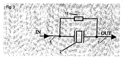
- Fig. 3 an equivalent circuit diagram for a condensate bridge is shown connecting the transmission line 6 (In) to the reception line 7 (Out). Between two lines here a piezoelectric element is drawn for the drive / receiving unit 2. Such elements usually have very high output impedances.
- the condensate bridge acts as a resistor 12, via which the transmission line 6 is connected directly to the receiving line 7, so that inter alia, an overlay of the two signals occurs. It is also possible for the oscillation frequency to change as a result of this condensate bridge in such a way that the control / evaluation unit 5 switches to demolition frequency, so that the measuring device no longer functions.
- the third line 8 is formed as a shield of the receiving line 7. Furthermore, in this embodiment, the voltage source 9 ground. This embodiment is not included in the invention.
- the impedance of the voltage source 9, to which the third line 8 is applied is generally smaller than the impedance of a condensate bridge. In other words, a direct connection between the transmission line 6 and the reception line 7 does not occur, since the third line 8 is located between the two and lies at an output impedance which is substantially smaller than the impedance of the condensate bridge.
- the effect of a condensate bridge is then that quasi a voltage regulator is formed, which reduces the voltage of the received signal. Due to the design as a shield, the usual benefits of shielding arise.
- the protection of the shielded receiving line 7 against radiation is, however, more relevant in embodiments in which the tube extension 11 is not made of metal.
- the application to ground is very easy to implement, but are thus the receiving line 7 and the third line 8 at different potentials, making the line capacitance noticeable as a capacitive resistance between the receiving line and shield, which reduces the received signal.
- the capacitance of this capacitor of receiving line 7 and third line 8, above all can be very large.
- the third line 8 and ground as voltage source 9 will help against the effects of the condensate bridge, capacitive losses will occur.
- Fig. 5 shows the effect of a condensate bridge between transmitter 6 and receiving line 7 for the embodiment not included in the invention Fig. 4 ,
- two resistors 12 between which through the third line 8 is ground. Therefore, there is no direct effect of the transmit 6 on the Receiving line 7. Since the receiving line 7 and the third line 8 at different potentials, the received signal is attenuated by current flow.
- Fig. 6 shows the embodiment in which the third line 8 is at a guard potential.
- the third line is therefore always at the same potential as the receiving line 7.
- the voltage source 9 is here, for example, an operational amplifier with a correspondingly low output impedance.
- the effects of a condensate bridge on the receiving line 7 are therefore still minimized.
- the low output impedance thus reduces the direct effects of the condensate bridge and the appropriate choice of the potential at which the third line is located can prevent the capacitive effects that occur.
Landscapes
- Physics & Mathematics (AREA)
- Acoustics & Sound (AREA)
- Electromagnetism (AREA)
- Thermal Sciences (AREA)
- Fluid Mechanics (AREA)
- General Physics & Mathematics (AREA)
- Arrangements For Transmission Of Measured Signals (AREA)
- Preventing Corrosion Or Incrustation Of Metals (AREA)
- Measurement Of Mechanical Vibrations Or Ultrasonic Waves (AREA)
- Apparatuses For Generation Of Mechanical Vibrations (AREA)
Claims (4)
- Dispositif destiné à la mesure et/ou la surveillance d'une grandeur process physique ou chimique d'un produit,
avec une unité apte à vibrer (1),
avec une unité d'entraînement / de réception (2),qui comporte au minimum une entrée de signal (3) et une sortie de signal (4),
etqui excite l'unité apte à vibrer (1) en vibrations,
ouqui reçoit ses vibrations,avec une unité de régulation / d'exploitation (5),qui comporte au minimum une entrée de signal (3) et une sortie de signal (4),qui régule l'unité d'entraînement / de réception,
ouqui exploite les vibrations de l'unité apte à vibrer (1),et
avec au moins un câble d'émission (6) et un câble de réception (7) entre l'unité de régulation / d'exploitation (5) et l'unité d'entraînement / de réception (2),le câble d'émission (6) étant relié avec la sortie de signal (4) de l'unité de régulation / d'exploitation (5) et l'entrée de signal (3) de l'unité d'entraînement / de réception (2), etle câble de réception (7) étant relié avec la sortie de signal (4) de l'unité d'entraînement / de réception (2) et l'entrée de signal (3) de l'unité de régulation / d'exploitation (5),le câble d'émission (6) et le câble de réception (7) étant reliés avec l'unité de régulation / d'exploitation (5) et avec l'unité d'entraînement / de réception (2) par l'intermédiaire de connecteurs (10),pour lequel est prévu un troisième câble,qui est conçu et disposé de telle sortecaractérisé en ceà se trouver dans la zone des connecteurs (10), entre le câble d'émission (6) et le câble de réception (7),
que le troisième câble (8)est relié avec une source de tension (9),etqui présente une impédance de sortie inférieure à l'impédance d'un pont de condensateur entre le câble d'émission (6) et le câble de réception (7), dans la zone des connecteurs (10),
que concernant la source de tension (9), avec laquelle le troisième câble (8) est relié, il s'agit d'une unité électronique avec une faible impédance de sortie, laquelle est conçue de telle manière que le troisième câble (8) se trouve au même potentiel que le câble de réception (7). - Dispositif selon la revendication 1,caractérisé en ceque, concernant le troisième câble (8), il s'agit d'un blindage du câble de réception (7).
- Dispositif selon la revendication 1,caractérisé en ceque l'unité d'entraînement / de réception (2) comporte au moins un élément piézoélectrique.
- Dispositif selon la revendication 1 ou 3,caractérisé en ceque l'unité d'entraînement / de réception (2) comporte exactement un élément piézoélectrique.
Applications Claiming Priority (3)
| Application Number | Priority Date | Filing Date | Title |
|---|---|---|---|
| DE10308087 | 2003-02-24 | ||
| DE10308087A DE10308087A1 (de) | 2003-02-24 | 2003-02-24 | Schutz vor den Effekten von Kondensatbrücken |
| PCT/EP2004/001310 WO2004075417A2 (fr) | 2003-02-24 | 2004-02-12 | Protection contre les effets de ponts de condensation |
Publications (3)
| Publication Number | Publication Date |
|---|---|
| EP1597545A2 EP1597545A2 (fr) | 2005-11-23 |
| EP1597545B1 EP1597545B1 (fr) | 2006-10-11 |
| EP1597545B2 true EP1597545B2 (fr) | 2012-06-13 |
Family
ID=32841872
Family Applications (1)
| Application Number | Title | Priority Date | Filing Date |
|---|---|---|---|
| EP04710373A Expired - Lifetime EP1597545B2 (fr) | 2003-02-24 | 2004-02-12 | Protection contre les effets de ponts de condensation |
Country Status (7)
| Country | Link |
|---|---|
| US (1) | US7513151B2 (fr) |
| EP (1) | EP1597545B2 (fr) |
| CN (1) | CN100378441C (fr) |
| AT (1) | ATE342491T1 (fr) |
| DE (2) | DE10308087A1 (fr) |
| RU (1) | RU2296957C2 (fr) |
| WO (1) | WO2004075417A2 (fr) |
Families Citing this family (10)
| Publication number | Priority date | Publication date | Assignee | Title |
|---|---|---|---|---|
| US7490516B2 (en) * | 2006-01-26 | 2009-02-17 | Rosemount Inc. | Manual powered process transmitter |
| DE102006033819A1 (de) * | 2006-07-19 | 2008-01-24 | Endress + Hauser Gmbh + Co. Kg | Vorrichtung zur Bestimmung und/oder Überwachung einer Prozessgröße eines Mediums |
| DE102008032887A1 (de) * | 2008-07-14 | 2010-01-21 | Endress + Hauser Gmbh + Co. Kg | Vorrichtung zur Bestimmung und/oder Überwachung einer Prozessgröße und Verfahren zur Prüfung einer Vorrichtung |
| DE102008052813A1 (de) * | 2008-10-15 | 2010-04-29 | Endress + Hauser Conducta Gesellschaft für Mess- und Regeltechnik mbH + Co. KG | Messvorrichtung und Verfahren für eine Feuchtigkeitsdetektion an einem Messpannungseingang einer solchen Messvorrichtung |
| US9366560B2 (en) * | 2013-08-01 | 2016-06-14 | John Cacciola | Detector for detecting a change in a fluid level and generating a digital signal |
| DE102013114045A1 (de) * | 2013-12-13 | 2015-06-18 | Endress + Hauser Gmbh + Co. Kg | System zur Bestimmung und/oder Überwachung einer Prozessgröße eines Mediums |
| CN104006863A (zh) * | 2014-05-07 | 2014-08-27 | 含山县大力精密机械有限公司 | 一种一体式铸造液位音叉 |
| DE102015100661A1 (de) * | 2015-01-19 | 2016-07-21 | Endress + Hauser Flowtec Ag | Vorrichtung zur Bestimmung und/oder Überwachung mindestens einer physikalischen oder chemischen Prozessgröße eines Mediums |
| DE102023118598A1 (de) * | 2023-07-13 | 2025-01-16 | Endress+Hauser SE+Co. KG | Vibrationssensor |
| DE102024100587A1 (de) * | 2024-01-10 | 2025-07-10 | Vega Grieshaber Kg | Vibrationssensor mit Selbsttestfunktion |
Family Cites Families (16)
| Publication number | Priority date | Publication date | Assignee | Title |
|---|---|---|---|---|
| DE3336991A1 (de) * | 1983-10-11 | 1985-05-02 | Endress U. Hauser Gmbh U. Co, 7867 Maulburg | Vorrichtung zur feststellung und/oder ueberwachung eines vorbestimmten fuellstands in einem behaelter |
| DE3740598C2 (de) * | 1987-11-30 | 1998-03-26 | Grieshaber Vega Kg | Schwingeinheit für Füllstand-Vibrations-Grenzschalter |
| US5060484A (en) * | 1990-06-12 | 1991-10-29 | Scotsman Group, Inc. | Bin level control circuit and transducer mounting system for an ice making machine |
| DE4133936A1 (de) * | 1991-10-14 | 1993-04-15 | Sachsenwerk Ag | Anzeigeeinrichtung fuer elektrische wechselspannungen |
| DE4201360C2 (de) * | 1992-01-20 | 1995-04-27 | Uwt Apparate Gmbh | Einrichtung zur Füllstandsmessung |
| DE4232659C2 (de) * | 1992-09-29 | 1996-07-25 | Endress Hauser Gmbh Co | Vorrichtung zur Feststellung und/oder Überwachung eines vorbestimmten Füllstands in einem Behälter |
| DE4329742C2 (de) * | 1993-09-03 | 2003-03-20 | Dieter Haaf | Elektrode zum Messen elektrochemischer Größen einer Probe |
| JP3421747B2 (ja) * | 1995-02-15 | 2003-06-30 | セイコーエプソン株式会社 | 圧電発振器及び電圧制御発振器 |
| DE19621449C2 (de) * | 1996-05-29 | 2000-11-30 | Grieshaber Vega Kg | Vibrationsresonator, Verfahren zum Betreiben eines solchen Vibrationsresonators und Vibrations-Füllstand-Grenzschalter mit einem solchen Vibrationsresonator |
| RU2126957C1 (ru) * | 1997-04-25 | 1999-02-27 | Банщиков Алексей Юрьевич | Датчик положения уровня |
| GB9807910D0 (en) * | 1998-04-14 | 1998-06-10 | Klinger Fluid Instrumentation | Apparatus for sensing the level of contents in a container |
| DE19932689C1 (de) * | 1999-05-29 | 2000-10-05 | Erhardt & Leimer Gmbh | Verfahren und Vorrichtung zum Feststellen von Metallkörpern, die sich auf einer laufenden Bahn befinden |
| DE10050299A1 (de) * | 2000-10-10 | 2002-04-11 | Endress Hauser Gmbh Co | Vorrichtung zur Bestimmung und/oder Überwachung der Viskosität eines Mediums in einem Behälter |
| DE10057974A1 (de) * | 2000-11-22 | 2002-05-23 | Endress Hauser Gmbh Co | Verfahren und Vorrichtung zur Feststellung und/oder Überwachung des Füllstands eines Mediums in einem Behälter bzw. zur Ermittlung der Dichte eines Mediums in einem Behälter |
| CN2508235Y (zh) * | 2001-12-05 | 2002-08-28 | 武汉大学 | 容器定点液位的超声波检测仪 |
| WO2005012920A1 (fr) * | 2003-07-30 | 2005-02-10 | Murata Manufacturing Co., Ltd. | Capteur de quantité physique |
-
2003
- 2003-02-24 DE DE10308087A patent/DE10308087A1/de not_active Ceased
-
2004
- 2004-02-12 US US10/546,763 patent/US7513151B2/en not_active Expired - Lifetime
- 2004-02-12 WO PCT/EP2004/001310 patent/WO2004075417A2/fr not_active Ceased
- 2004-02-12 AT AT04710373T patent/ATE342491T1/de not_active IP Right Cessation
- 2004-02-12 DE DE502004001721T patent/DE502004001721D1/de not_active Expired - Lifetime
- 2004-02-12 EP EP04710373A patent/EP1597545B2/fr not_active Expired - Lifetime
- 2004-02-12 RU RU2005130019/28A patent/RU2296957C2/ru active
- 2004-02-12 CN CNB2004800045172A patent/CN100378441C/zh not_active Expired - Fee Related
Also Published As
| Publication number | Publication date |
|---|---|
| DE10308087A1 (de) | 2004-09-09 |
| RU2005130019A (ru) | 2006-02-20 |
| RU2296957C2 (ru) | 2007-04-10 |
| DE502004001721D1 (de) | 2006-11-23 |
| CN100378441C (zh) | 2008-04-02 |
| EP1597545B1 (fr) | 2006-10-11 |
| EP1597545A2 (fr) | 2005-11-23 |
| ATE342491T1 (de) | 2006-11-15 |
| US20060284626A1 (en) | 2006-12-21 |
| CN1751230A (zh) | 2006-03-22 |
| WO2004075417A2 (fr) | 2004-09-02 |
| WO2004075417A3 (fr) | 2004-10-28 |
| US7513151B2 (en) | 2009-04-07 |
Similar Documents
| Publication | Publication Date | Title |
|---|---|---|
| DE102009029490B4 (de) | Füllstandsmessgerät | |
| DE69523649T2 (de) | Austauschbarer auf mehrere Messgrössen empfindlicher Wirbelsensor | |
| DE10022891A1 (de) | Vorrichtung zur Feststellung und/oder Überwachung des Füllstandes eines Füllguts in einem Behälter | |
| DE3910297C2 (fr) | ||
| EP3983761B1 (fr) | Multicapteur vibronique | |
| EP3983760B1 (fr) | Multicapteur vibronique | |
| EP3983762B1 (fr) | Multicapteur vibronique | |
| EP0065511B1 (fr) | Instrument de mesure avec un élément de détection piézoélectrique | |
| EP1597545B2 (fr) | Protection contre les effets de ponts de condensation | |
| DE102006033819A1 (de) | Vorrichtung zur Bestimmung und/oder Überwachung einer Prozessgröße eines Mediums | |
| EP2623944B1 (fr) | Système de mesure du niveau de remplissage fonctionnant selon le principe de radar | |
| DE102020116278A1 (de) | Vibronischer Multisensor | |
| WO2021170339A1 (fr) | Multicapteur vibronique | |
| WO2017108280A1 (fr) | Appareil de terrain de la technique de mesure de processus | |
| EP2798317B1 (fr) | Dispositif de détermination et/ou de surveillance d'une valeur limite d'une grandeur de procédé | |
| DE102012015887B4 (de) | Vortex-Durchflussmessgerät | |
| DE102010002608A1 (de) | Vorrichtung zur Bestimmung mindestens einer Prozessgröße | |
| DE102007038022B4 (de) | Vorrichtung zur Bestimmung und/oder Überwachung einer Prozessgröße | |
| EP3314210B1 (fr) | Appareil émetteur de champs doté d'un circuit de compensation pour l'élimination des impacts environnementaux | |
| DE102013114045A1 (de) | System zur Bestimmung und/oder Überwachung einer Prozessgröße eines Mediums | |
| WO2005085769A2 (fr) | Dispositif pour determiner et/ou surveiller une variable de processus | |
| EP1108989A1 (fr) | Dispositif pour la mesure d'un débit d'un fluide de mesure dans un conduit de mesure | |
| DE102005062813B4 (de) | Füllstandmessanordnung mit einer Sicherheitsabschaltung bei hohen Temperaturen | |
| DE102023118598A1 (de) | Vibrationssensor | |
| WO2013171046A1 (fr) | Bloc de jonction, dispositif de connexion l'utilisant et appareil de terrain équipé d'un tel dispositif de connexion |
Legal Events
| Date | Code | Title | Description |
|---|---|---|---|
| PUAI | Public reference made under article 153(3) epc to a published international application that has entered the european phase |
Free format text: ORIGINAL CODE: 0009012 |
|
| 17P | Request for examination filed |
Effective date: 20050714 |
|
| AK | Designated contracting states |
Kind code of ref document: A2 Designated state(s): AT BE BG CH CY CZ DE DK EE ES FI FR GB GR HU IE IT LI LU MC NL PT RO SE SI SK TR |
|
| AX | Request for extension of the european patent |
Extension state: AL LT LV MK |
|
| DAX | Request for extension of the european patent (deleted) | ||
| GRAP | Despatch of communication of intention to grant a patent |
Free format text: ORIGINAL CODE: EPIDOSNIGR1 |
|
| GRAS | Grant fee paid |
Free format text: ORIGINAL CODE: EPIDOSNIGR3 |
|
| GRAA | (expected) grant |
Free format text: ORIGINAL CODE: 0009210 |
|
| AK | Designated contracting states |
Kind code of ref document: B1 Designated state(s): AT BE BG CH CY CZ DE DK EE ES FI FR GB GR HU IE IT LI LU MC NL PT RO SE SI SK TR |
|
| PG25 | Lapsed in a contracting state [announced via postgrant information from national office to epo] |
Ref country code: RO Free format text: LAPSE BECAUSE OF FAILURE TO SUBMIT A TRANSLATION OF THE DESCRIPTION OR TO PAY THE FEE WITHIN THE PRESCRIBED TIME-LIMIT Effective date: 20061011 Ref country code: CZ Free format text: LAPSE BECAUSE OF FAILURE TO SUBMIT A TRANSLATION OF THE DESCRIPTION OR TO PAY THE FEE WITHIN THE PRESCRIBED TIME-LIMIT Effective date: 20061011 Ref country code: FI Free format text: LAPSE BECAUSE OF FAILURE TO SUBMIT A TRANSLATION OF THE DESCRIPTION OR TO PAY THE FEE WITHIN THE PRESCRIBED TIME-LIMIT Effective date: 20061011 Ref country code: IE Free format text: LAPSE BECAUSE OF FAILURE TO SUBMIT A TRANSLATION OF THE DESCRIPTION OR TO PAY THE FEE WITHIN THE PRESCRIBED TIME-LIMIT Effective date: 20061011 Ref country code: NL Free format text: LAPSE BECAUSE OF FAILURE TO SUBMIT A TRANSLATION OF THE DESCRIPTION OR TO PAY THE FEE WITHIN THE PRESCRIBED TIME-LIMIT Effective date: 20061011 Ref country code: SI Free format text: LAPSE BECAUSE OF FAILURE TO SUBMIT A TRANSLATION OF THE DESCRIPTION OR TO PAY THE FEE WITHIN THE PRESCRIBED TIME-LIMIT Effective date: 20061011 Ref country code: SK Free format text: LAPSE BECAUSE OF FAILURE TO SUBMIT A TRANSLATION OF THE DESCRIPTION OR TO PAY THE FEE WITHIN THE PRESCRIBED TIME-LIMIT Effective date: 20061011 |
|
| REG | Reference to a national code |
Ref country code: GB Ref legal event code: FG4D Free format text: NOT ENGLISH |
|
| REG | Reference to a national code |
Ref country code: CH Ref legal event code: EP |
|
| GBT | Gb: translation of ep patent filed (gb section 77(6)(a)/1977) |
Effective date: 20061012 |
|
| REG | Reference to a national code |
Ref country code: IE Ref legal event code: FG4D Free format text: LANGUAGE OF EP DOCUMENT: GERMAN |
|
| REF | Corresponds to: |
Ref document number: 502004001721 Country of ref document: DE Date of ref document: 20061123 Kind code of ref document: P |
|
| PG25 | Lapsed in a contracting state [announced via postgrant information from national office to epo] |
Ref country code: SE Free format text: LAPSE BECAUSE OF FAILURE TO SUBMIT A TRANSLATION OF THE DESCRIPTION OR TO PAY THE FEE WITHIN THE PRESCRIBED TIME-LIMIT Effective date: 20070111 Ref country code: DK Free format text: LAPSE BECAUSE OF FAILURE TO SUBMIT A TRANSLATION OF THE DESCRIPTION OR TO PAY THE FEE WITHIN THE PRESCRIBED TIME-LIMIT Effective date: 20070111 Ref country code: BG Free format text: LAPSE BECAUSE OF FAILURE TO SUBMIT A TRANSLATION OF THE DESCRIPTION OR TO PAY THE FEE WITHIN THE PRESCRIBED TIME-LIMIT Effective date: 20070111 |
|
| PG25 | Lapsed in a contracting state [announced via postgrant information from national office to epo] |
Ref country code: ES Free format text: LAPSE BECAUSE OF FAILURE TO SUBMIT A TRANSLATION OF THE DESCRIPTION OR TO PAY THE FEE WITHIN THE PRESCRIBED TIME-LIMIT Effective date: 20070122 |
|
| REG | Reference to a national code |
Ref country code: HU Ref legal event code: AG4A Ref document number: E000914 Country of ref document: HU |
|
| PG25 | Lapsed in a contracting state [announced via postgrant information from national office to epo] |
Ref country code: MC Free format text: LAPSE BECAUSE OF NON-PAYMENT OF DUE FEES Effective date: 20070228 |
|
| ET | Fr: translation filed | ||
| PG25 | Lapsed in a contracting state [announced via postgrant information from national office to epo] |
Ref country code: PT Free format text: LAPSE BECAUSE OF FAILURE TO SUBMIT A TRANSLATION OF THE DESCRIPTION OR TO PAY THE FEE WITHIN THE PRESCRIBED TIME-LIMIT Effective date: 20070319 |
|
| NLV1 | Nl: lapsed or annulled due to failure to fulfill the requirements of art. 29p and 29m of the patents act | ||
| REG | Reference to a national code |
Ref country code: IE Ref legal event code: FD4D |
|
| PLBI | Opposition filed |
Free format text: ORIGINAL CODE: 0009260 |
|
| PLAX | Notice of opposition and request to file observation + time limit sent |
Free format text: ORIGINAL CODE: EPIDOSNOBS2 |
|
| 26 | Opposition filed |
Opponent name: UWT APPARATE GMBH Effective date: 20070711 |
|
| PLBB | Reply of patent proprietor to notice(s) of opposition received |
Free format text: ORIGINAL CODE: EPIDOSNOBS3 |
|
| BERE | Be: lapsed |
Owner name: ENDRESS + HAUSER G.M.B.H. + CO. KG Effective date: 20070228 |
|
| PG25 | Lapsed in a contracting state [announced via postgrant information from national office to epo] |
Ref country code: BE Free format text: LAPSE BECAUSE OF NON-PAYMENT OF DUE FEES Effective date: 20070228 |
|
| PLBP | Opposition withdrawn |
Free format text: ORIGINAL CODE: 0009264 |
|
| PG25 | Lapsed in a contracting state [announced via postgrant information from national office to epo] |
Ref country code: GR Free format text: LAPSE BECAUSE OF FAILURE TO SUBMIT A TRANSLATION OF THE DESCRIPTION OR TO PAY THE FEE WITHIN THE PRESCRIBED TIME-LIMIT Effective date: 20070112 |
|
| PGFP | Annual fee paid to national office [announced via postgrant information from national office to epo] |
Ref country code: IT Payment date: 20080223 Year of fee payment: 5 |
|
| PG25 | Lapsed in a contracting state [announced via postgrant information from national office to epo] |
Ref country code: AT Free format text: LAPSE BECAUSE OF NON-PAYMENT OF DUE FEES Effective date: 20070212 |
|
| PGFP | Annual fee paid to national office [announced via postgrant information from national office to epo] |
Ref country code: FR Payment date: 20080214 Year of fee payment: 5 |
|
| REG | Reference to a national code |
Ref country code: CH Ref legal event code: PL |
|
| PG25 | Lapsed in a contracting state [announced via postgrant information from national office to epo] |
Ref country code: LI Free format text: LAPSE BECAUSE OF NON-PAYMENT OF DUE FEES Effective date: 20080229 Ref country code: EE Free format text: LAPSE BECAUSE OF FAILURE TO SUBMIT A TRANSLATION OF THE DESCRIPTION OR TO PAY THE FEE WITHIN THE PRESCRIBED TIME-LIMIT Effective date: 20061011 Ref country code: CH Free format text: LAPSE BECAUSE OF NON-PAYMENT OF DUE FEES Effective date: 20080229 |
|
| PG25 | Lapsed in a contracting state [announced via postgrant information from national office to epo] |
Ref country code: CY Free format text: LAPSE BECAUSE OF FAILURE TO SUBMIT A TRANSLATION OF THE DESCRIPTION OR TO PAY THE FEE WITHIN THE PRESCRIBED TIME-LIMIT Effective date: 20061011 Ref country code: LU Free format text: LAPSE BECAUSE OF NON-PAYMENT OF DUE FEES Effective date: 20070212 |
|
| PG25 | Lapsed in a contracting state [announced via postgrant information from national office to epo] |
Ref country code: TR Free format text: LAPSE BECAUSE OF FAILURE TO SUBMIT A TRANSLATION OF THE DESCRIPTION OR TO PAY THE FEE WITHIN THE PRESCRIBED TIME-LIMIT Effective date: 20061011 |
|
| REG | Reference to a national code |
Ref country code: FR Ref legal event code: ST Effective date: 20091030 |
|
| PG25 | Lapsed in a contracting state [announced via postgrant information from national office to epo] |
Ref country code: FR Free format text: LAPSE BECAUSE OF NON-PAYMENT OF DUE FEES Effective date: 20090302 |
|
| PLAY | Examination report in opposition despatched + time limit |
Free format text: ORIGINAL CODE: EPIDOSNORE2 |
|
| PG25 | Lapsed in a contracting state [announced via postgrant information from national office to epo] |
Ref country code: IT Free format text: LAPSE BECAUSE OF NON-PAYMENT OF DUE FEES Effective date: 20090212 |
|
| PLBC | Reply to examination report in opposition received |
Free format text: ORIGINAL CODE: EPIDOSNORE3 |
|
| PLAY | Examination report in opposition despatched + time limit |
Free format text: ORIGINAL CODE: EPIDOSNORE2 |
|
| PLBC | Reply to examination report in opposition received |
Free format text: ORIGINAL CODE: EPIDOSNORE3 |
|
| PUAH | Patent maintained in amended form |
Free format text: ORIGINAL CODE: 0009272 |
|
| STAA | Information on the status of an ep patent application or granted ep patent |
Free format text: STATUS: PATENT MAINTAINED AS AMENDED |
|
| 27A | Patent maintained in amended form |
Effective date: 20120613 |
|
| AK | Designated contracting states |
Kind code of ref document: B2 Designated state(s): AT BE BG CH CY CZ DE DK EE ES FI FR GB GR HU IE IT LI LU MC NL PT RO SE SI SK TR |
|
| REG | Reference to a national code |
Ref country code: DE Ref legal event code: R102 Ref document number: 502004001721 Country of ref document: DE Effective date: 20120613 |
|
| PGFP | Annual fee paid to national office [announced via postgrant information from national office to epo] |
Ref country code: HU Payment date: 20150218 Year of fee payment: 12 |
|
| REG | Reference to a national code |
Ref country code: DE Ref legal event code: R081 Ref document number: 502004001721 Country of ref document: DE Owner name: ENDRESS+HAUSER SE+CO. KG, DE Free format text: FORMER OWNER: ENDRESS + HAUSER GMBH + CO. KG, 79689 MAULBURG, DE |
|
| PG25 | Lapsed in a contracting state [announced via postgrant information from national office to epo] |
Ref country code: HU Free format text: THE PATENT HAS BEEN ANNULLED BY A DECISION OF A NATIONAL AUTHORITY Effective date: 20120613 |
|
| PGFP | Annual fee paid to national office [announced via postgrant information from national office to epo] |
Ref country code: GB Payment date: 20190218 Year of fee payment: 16 |
|
| GBPC | Gb: european patent ceased through non-payment of renewal fee |
Effective date: 20200212 |
|
| PG25 | Lapsed in a contracting state [announced via postgrant information from national office to epo] |
Ref country code: GB Free format text: LAPSE BECAUSE OF NON-PAYMENT OF DUE FEES Effective date: 20200212 |
|
| PGFP | Annual fee paid to national office [announced via postgrant information from national office to epo] |
Ref country code: DE Payment date: 20220217 Year of fee payment: 19 |
|
| REG | Reference to a national code |
Ref country code: DE Ref legal event code: R119 Ref document number: 502004001721 Country of ref document: DE |
|
| PG25 | Lapsed in a contracting state [announced via postgrant information from national office to epo] |
Ref country code: DE Free format text: LAPSE BECAUSE OF NON-PAYMENT OF DUE FEES Effective date: 20230901 |