EP1597555B1 - Anordnung und verfahren zur schätzung der höhe des schwerpunkts eines fahrzeugs - Google Patents
Anordnung und verfahren zur schätzung der höhe des schwerpunkts eines fahrzeugs Download PDFInfo
- Publication number
- EP1597555B1 EP1597555B1 EP04711792A EP04711792A EP1597555B1 EP 1597555 B1 EP1597555 B1 EP 1597555B1 EP 04711792 A EP04711792 A EP 04711792A EP 04711792 A EP04711792 A EP 04711792A EP 1597555 B1 EP1597555 B1 EP 1597555B1
- Authority
- EP
- European Patent Office
- Prior art keywords
- vehicle
- wheels
- gravity
- centre
- height
- Prior art date
- Legal status (The legal status is an assumption and is not a legal conclusion. Google has not performed a legal analysis and makes no representation as to the accuracy of the status listed.)
- Expired - Lifetime
Links
- 230000005484 gravity Effects 0.000 title claims abstract description 87
- 238000000034 method Methods 0.000 title claims abstract description 24
- 230000001133 acceleration Effects 0.000 claims abstract description 44
- 230000008859 change Effects 0.000 claims description 33
- 238000005259 measurement Methods 0.000 claims description 21
- 230000000977 initiatory effect Effects 0.000 claims description 10
- 230000006870 function Effects 0.000 description 4
- 230000003019 stabilising effect Effects 0.000 description 4
- 230000008901 benefit Effects 0.000 description 3
- 239000000203 mixture Substances 0.000 description 2
- 229910000831 Steel Inorganic materials 0.000 description 1
- 230000008878 coupling Effects 0.000 description 1
- 238000010168 coupling process Methods 0.000 description 1
- 238000005859 coupling reaction Methods 0.000 description 1
- 238000001514 detection method Methods 0.000 description 1
- 230000000694 effects Effects 0.000 description 1
- 230000008569 process Effects 0.000 description 1
- 230000003068 static effect Effects 0.000 description 1
- 239000010959 steel Substances 0.000 description 1
- 239000000725 suspension Substances 0.000 description 1
Images

Classifications
-
- G—PHYSICS
- G01—MEASURING; TESTING
- G01M—TESTING STATIC OR DYNAMIC BALANCE OF MACHINES OR STRUCTURES; TESTING OF STRUCTURES OR APPARATUS, NOT OTHERWISE PROVIDED FOR
- G01M1/00—Testing static or dynamic balance of machines or structures
- G01M1/12—Static balancing; Determining position of centre of gravity
- G01M1/122—Determining position of centre of gravity
-
- B—PERFORMING OPERATIONS; TRANSPORTING
- B62—LAND VEHICLES FOR TRAVELLING OTHERWISE THAN ON RAILS
- B62D—MOTOR VEHICLES; TRAILERS
- B62D37/00—Stabilising vehicle bodies without controlling suspension arrangements
-
- B—PERFORMING OPERATIONS; TRANSPORTING
- B60—VEHICLES IN GENERAL
- B60G—VEHICLE SUSPENSION ARRANGEMENTS
- B60G2400/00—Indexing codes relating to detected, measured or calculated conditions or factors
- B60G2400/60—Load
- B60G2400/63—Location of the center of gravity
Definitions
- the invention relates to an arrangement and a method for estimating the height of the centre of gravity of a vehicle according to the preambles of claims 1 and 14.
- US 6 370 938 refers to a method and a device for estimating the height of the centre of gravity of a vehicle.
- the height of the centre of gravity is here determined as a function of the speed of at least one wheel of the vehicle and the load to which the wheel is subjected when the vehicle is negotiating a bend.
- US 6 044 319 in turn describes the use of signals from axle load sensors to calculate the height of the centre of gravity based on variations in the road gradients and/or the acceleration of the vehicle, which is used in a process for attenuating the yawing moment during braking of a vehicle with an anti-lock brake system, when the wheels show different coefficient of friction against the road surface.
- the extent of rocking movements of the vehicle which occur on road gradients, or during acceleration of the vehicle may be used since they are approximately proportional to the height of the centre of gravity.
- Many vehicles comprise electrically controlled stabilising systems adapted to providing the vehicle with optimum stability during operation.
- stabilising systems have to provide reliable information about a multiplicity of parameter values which are measured by sensors or estimated in some other way.
- One parameter which is of great importance for the functioning of such stabilising systems is the position of the vehicle's centre of gravity. Estimating the position of the centre of gravity in a horizontal plane can thus be done with good precision by means of load sensors which detect how the vehicle's weight is distributed over the vehicle's wheels.
- load sensors which detect how the vehicle's weight is distributed over the vehicle's wheels.
- it is difficult to determine with correspondingly good precision the height position of the centre of gravity of a freight vehicle since the height position can vary considerably with the composition of the cargo.
- Conventional stabilising systems may therefore frequently fail to fully provide a freight vehicle with optimum stability during operation.
- the object of the present invention is to provide an arrangement and a method which enable better and more reliable estimation of a vehicle's centre of gravity in the height direction. Another object is that it should be possible for such estimation to be done automatically and during normal operation of the vehicle.
- the load values on the various wheels are measured with advantage by means of existing load sensors which, for example, measure the air pressure in air bellows which are arranged between the chassis and the vehicle's various wheelshafts or separately suspended individual wheels.
- the second sensor detects a parameter value which is related to the vehicle's acceleration. Supposing that the vehicle's centre of gravity is situated higher than the wheelshafts, the result during acceleration of the vehicle is an increased load on the vehicle's rear wheels relative to its front wheels.
- the change in the load values on the wheels is related to the amount of acceleration and the height of the centre of gravity above the wheelshafts.
- the height of the centre of gravity can therefore be determined on the basis of knowing the load change on the vehicle's wheels and the amount of acceleration. Retardation of a vehicle results correspondingly in an increased load on the vehicle's front wheels relative to the rear wheels.
- the change in the load values on the wheels is related to the amount of acceleration and the height of the centre of gravity above the wheelshafts.
- the second sensor may be an accelerometer which directly detects the vehicle's acceleration as a parameter value.
- the vehicle's existing sensors which measure its speed may be used.
- Speed is a parameter value which is related to acceleration. Acceleration can be determined on the basis of knowing at least two speed values and the difference between said speed values.
- the third sensor thus detects a parameter value which is related to the angle of inclination of the vehicle.
- Driving a vehicle with one forward wheelshaft and one rear wheelshaft uphill results in an increased load on the rear axle relative to the front axle as compared with driving on a more level running surface.
- the change in the load values on the wheels is related to the gradient and the height of the centre of gravity.
- the third sensor may be a slope sensor which detects a parameter value which is related to the vehicle's angle of inclination.
- Driving downhill results correspondingly in an increased load on the front axle relative to the rear axle as compared with driving on a more level running surface.
- the second sensor and the third sensor thus detect two parameter values which define various states of the vehicle which cause variation in the load on the vehicle's wheels. Any change in such parameter values thus also results in a change in the load on the vehicle's wheels.
- the amount of load change is related to the height of the centre of gravity in the vehicle. The higher the centre of gravity of the vehicle, the more the load on the various wheels will change between the first state and the second.
- the amount of load change is also related to the extent to which the parameter values change. Estimating the height of the centre of gravity with good precision requires not only knowing said load values on the wheels and said parameter values but also the availability of information concerning the specific vehicle, such as the distance between its wheelshafts, etc. Such necessary geometrical values specific to the vehicle may be stored in a memory unit associated with the control unit. During normal operation of the vehicle, suitable second states in which the control unit can automatically estimate the height of the centre of gravity of the vehicle with good precision are usually relatively frequent.
- the first state occurs when the vehicle's acceleration and angle of inclination are nil, the vehicle thus standing still on a level surface.
- Using such a first state is advantageous from several points of view.
- a vehicle is usually already in such a first state when cargo transshipment takes place, i.e. the vehicle will be standing still on a level surface.
- the load values on the wheels can therefore be determined quickly in the first state.
- the vehicle's total weight can be estimated as the aggregate of the load values on the wheels.
- the height of the centre of gravity in the vehicle's longitudinal direction is also easy to determine from knowing how the load is distributed among the vehicle's wheelshafts and from knowing the positions of the respective wheelshafts in the vehicle.
- the second state is reached when a parameter value which exceeds a reference value is obtained.
- the control unit is adapted to initiating negative acceleration of the vehicle by braking at least one of said wheels.
- certain specified wheels or wheelshafts of the vehicle may cause said change in the load values on the various wheels to become more pronounced.
- a supplementary brake such as a retarder which only brakes the vehicle's driven wheels may be used.
- the height of the centre of gravity can thereby be determined with better precision than when more evenly distributed braking of the vehicle's wheels is effected.
- the control unit may correspondingly initiate positive acceleration of the vehicle by powering at least one of said wheels. With suitably arranged driveshafts of the vehicle it is possible correspondingly to achieve a more pronounced change in the load distribution on the wheels during acceleration so that the height of the centre of gravity can be determined with greater precision.
- the first state also occurs when the vehicle is travelling at constant speed on a level surface.
- the control unit is adapted to estimating the height of the centre of gravity on the basis of the change between the first and second states in a numerical measurement which comprises a value with at least two load values.
- a numerical measurement needs to have the characteristic of changing significantly with the height of the centre of gravity.
- the numerical measurement may express the load distribution between two wheels of the vehicle. For example, when a vehicle is travelling on a steep gradient, there is a pronounced change in the load on said wheels between the first state and the second state. When the vehicle has a high centre of gravity, the result in this situation is a greater load change than when the vehicle has a low centre of gravity.
- the vehicle may comprise a tractor unit and at least one trailer. Such a trailer may be a so-called semitrailer. Other vehicle combinations may of course also be used. If the vehicle comprises a tractor unit and a trailer, the numerical measurement may express for example the load distribution between the tractor unit's wheels and the trailer's wheels. Alternatively, the numerical measurement may express the load on the tractor unit relative to the vehicle's total weight. Here again the numerical measurement will change significantly with the height of the centre of gravity.
- the control unit is adapted to automatically initiating estimation of the height of the centre of gravity when said second state is reached after at least one change in the vehicle's total weight has been identified.
- the first sensors detect when the vehicle's total weight changes after a cargo transshipment operation on the vehicle. It is thereupon found that a fresh estimate of the height of the centre of gravity needs to be made.
- the vehicle will preferably be standing still on a level surface. The control unit will therefore find that the vehicle is in a suitable first state.
- the first sensors detect the vehicle's total weight and how it is distributed over the vehicle's respective wheels.
- the control unit receives parameter values substantially continuously from the second sensor and the third sensor with a view to ascertaining when the vehicle reaches a suitable second state in which the height position of the centre of gravity can be determined.
- a suitable second state obtains, the control unit automatically estimates the height position of the centre of gravity.
- the second state may thus represent the vehicle travelling on a steep gradient or executing powerful braking or acceleration. Further estimates of the height of the centre of gravity may be made substantially continuously during ongoing normal operation of the vehicle.
- the height of the centre of gravity is preferably estimated as soon as an opportunity arises after a cargo transshipment operation.
- the arrangement may comprise a control which allows estimation of the height of the centre of gravity to be initiated manually.
- the control may for example be a button means which has to be pressed in or a suitably shaped lever or circuit-breaker which has to be moved to an active position.
- At least one of the first sensors is adapted to detecting load values on a wheelshaft which comprises at least two wheels.
- Heavy vehicles frequently comprise air bellows acting between the vehicle's chassis and wheelshafts.
- existing load sensors detect the pressure in the air bellows.
- first sensors may be adapted to detecting load values on all of the vehicle's wheels which are in contact with the running surface. In that case the load may be detected for each individual wheel so that the position of the centre of gravity in the vehicle's transverse direction can also be determined.
- Fig. 1 depicts a vehicle combination comprising a tractor unit 1 and a trailer 2, the trailer being in this case a semitrailer.
- the tractor unit 1 comprises a forward wheelshaft 3 and a rear wheelshaft 4.
- the tractor unit comprises a turntable 5 which allows coupling to the trailer 2.
- the trailer 2 comprises a rear wheelshaft 6.
- the front portion of the trailer 2 is supported by the turntable 5.
- load sensors 7a-c are arranged on the vehicle's respective wheelshafts 3, 4, 6.
- the load sensors 7a-c detect the loads on the respective wheelshafts 3, 4, 6.
- the load sensors 7a-c are with advantage already existing sensors adapted to detecting the air pressure in undepicted air bellows which are arranged between the vehicle's chassis and the respective wheelshafts.
- each of the load sensors 7a-c extend to a control unit 8 situated in the tractor unit 1.
- the tractor unit 8 thereby receives information substantially continuously concerning the prevailing load values on the respective wheelshafts 3, 4, 6.
- the vehicle also incorporates a schematically depicted slope sensor 9 which is adapted to detecting the vehicle's angle of inclination ⁇ .
- the slope sensor 9 is connected to the control unit 8 by an electrical line for carrying signal values which provide information about the vehicle's angle of inclination ⁇ .
- the vehicle also comprises a schematically depicted sensor 10 which detects the vehicle's speed.
- Such a sensor 10 may for example measure the rotation speed of the wheels.
- the sensor 10 may also be an already existing sensor for estimating the vehicle's speed.
- the control unit 8 receives information about the vehicle's speed from the sensor 10 via an electrical line and thereupon calculates a value of the vehicle's acceleration on the basis of information about the difference in speed between at least two measuring occasions close together in time.
- an accelerometer directly detecting the vehicle's acceleration may be used.
- Fig. 1 shows the vehicle combination standing still on a level surface.
- the slope sensor 9 detects that the angle of inclination is 0° and the speed sensor 10 detects that the speed is constantly nil.
- Cargo transshipment usually takes place in such a state, which is therefore preferably defined as a first state.
- a first state may obtain when the vehicle is travelling at constant speed on a level surface.
- the load sensor 7a detects the perpendicular force N 1 which acts upon the wheelshaft 3
- the load sensor 7b detects the perpendicular force N 2 which acts upon the wheelshaft 4
- the load sensor 7c detects the perpendicular force N 3 which acts upon the wheelshaft 6.
- the control unit 8 uses information about the values of the perpendicular forces N 1 , N 2 , N 3 to calculate the vehicle's total weight m tot as the aggregate of the perpendicular forces. Thereafter the control unit 8 uses information about the values of the perpendicular forces N 1 , N 2 , N 3 and geometrical values of the specific vehicle, concerning inter alia the mutual spacing of the wheelshafts 3, 4, 6 and the turntable 5, to calculate the tractor unit's weight m d and the trailer's weight m t . If the control unit 8 finds that the tractor unit's weight m d or the trailer's weight m t has changed relative to the latest estimate, this will be taken to mean that a cargo transshipment operation has taken place.
- Such a transshipment operation may also have changed the positions t t , t d of the centres of gravity of the members of the vehicle combination.
- the control unit 8 therefore also calculates the new position of the tractor unit's centre of gravity t d in the longitudinal direction of the vehicle and the new position of the trailer's centre of gravity t t in the longitudinal direction of the vehicle.
- the control unit 8 is adapted to estimating the vehicle's centres of gravity t t , t d in the height direction for the tractor unit 1 and the trailer 2. Such estimation is done automatically during normal operation of the vehicle as soon as the control unit 8 receives information that a second state has been reached in which there is a significant change in the loads N 1 , N 2 , N 3 on the wheelshafts 3, 4, 6 relative to those in the first state. Such a change in the loads N 1 , N 2 , N 3 on the wheelshafts 3, 4, 6 occurs when the vehicle travels on sufficiently steep gradients or executes powerful acceleration or retardation.
- the amount of load change is thus related to the vehicle's angle of inclination ⁇ and the vehicle's acceleration a.
- the acceleration a may of course even assume negative values during retardation of the vehicle.
- the control unit 8 receives information substantially continuously from the slope sensor 9 concerning the vehicle's angle of inclination ⁇ and uses information from signal values from the speed sensor 10 to calculate at short intervals of time the vehicle's acceleration a.
- Fig. 2 shows the vehicle travelling uphill at an angle of inclination ⁇ . In this case the angle of inclination ⁇ due to the gradient exceeds a reference value ⁇ ref which is stored in the control unit 8.
- Such an angle of inclination ⁇ has been found to be sufficient to enable good estimation of the height of the centre of gravity y d of the tractor unit and the centre of gravity y t of the trailer 2.
- the control unit 8 uses information about the vehicle's angle of inclination ⁇ , the change in the loads N 1 , N 2 , N 3 on the wheelshafts 3, 4, 6 relative to those in the first state, and values specific to the vehicle, such as axle spacing etc., to estimate said heights y d and y t of the centres of gravity. Estimation may also be done when the speed is constant so that there is no acceleration of the vehicle to affect the loads N 1 , N 2 , N 3 on the wheelshafts 3, 4, 6.
- Fig. 2 shows the tractor unit 1 and the trailer 2 separated to enable the forces acting upon the respective members 1, 2 of the vehicle combination to be shown more clearly.
- To calculate the height y d of the tractor unit's centre of gravity and the height y t of the trailer's centre of gravity it is possible, for example, to use the following mass balance equations and moment equations.
- This calculation model is merely an example and takes only static characteristics into account. It does not take into account dynamic characteristics such as, for example, suspension. A more sophisticated calculation model might of course also comprise dynamic characteristics.
- the control unit 8 thus automatically does a calculation of the heights of the centres of gravity y t , y d as soon as a suitable second state occurs during normal operation of the vehicle after a cargo transshipment operation. Such calculations may be done many times. At the same time an average value may be calculated in order to determine the heights y t , y d of the centres of gravity with greater accuracy.
- the second state obtains when the vehicle travels on a gradient at an angle of inclination ⁇ which is greater than a reference value ⁇ ref .
- the second state may also represent the vehicle accelerating at an acceleration value a which is greater than a stored reference value a ref , or braking of the vehicle which results in a more powerful retardation of the vehicle than a stored negative acceleration reference value -a ref .
- the braking may be applied to suitably selected wheelshafts 3, 4, 6. Such braking is applied with advantage to the wheels of the forward wheelshaft 3.
- the control unit 8 is thus adapted to automatic initiation of said estimation of the heights y t , y d of the centres of gravity upon receiving parameter values ⁇ , a which indicate a suitable second state has been reached after a cargo transshipment operation.
- the arrangement may comprise a control 11 in the vehicle's driving cab.
- the control is depicted schematically in Fig. 1. The driver is instructed to operate the control 11 when he/she wishes to obtain an estimate of the current heights y t , y d of the centres of gravity of the members of the vehicle combination.
- the vehicle braking or being on a gradient at a suitable angle of inclination thus provides the driver with the opportunity to initiate estimation of the heights y t , y d of the centres of gravity by operating the control 11.
- the control 11 may for example be a button means which has to be pressed in or a suitably shaped lever or circuit-breaker which has to be switched to an active position for such estimation to be done.
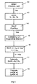
- Fig. 3 depicts a flowchart illustrating an embodiment of a method according to the invention.
- Step 12 detects whether the vehicle is in a first state.
- the control unit 8 uses such an indication to calculate the new position t d of the centre of gravity of the tractor unit 1 in the longitudinal direction of the vehicle and the new position t t of the centre of gravity of the trailer 2 in the longitudinal direction of the vehicle.
- the control unit 8 receives parameter values substantially continuously concerning the vehicle's acceleration a and angle of inclination ⁇ . At step 16 it then detects whether the vehicle's acceleration a exceeds the reference value a ref or is below a reference value -a ref . At the same time there is detection of whether the vehicle's angle of inclination ⁇ is greater than a reference value ⁇ ref . As soon as either of said parameter values a, ⁇ passes its respective reference value, the control unit 8 is adapted to doing an estimation of the heights y t , y d of the centres of gravity.
- the control unit 8 finds that the vehicle is in a suitable second state, and receives prevailing load values N 1 , N 2 , N 3 from the load sensors 7a-c. Thereafter, at step 17, the control unit 8 calculates a suitable numerical measurement M which has the characteristic of significantly changing with the heights y t , y d of the centres of gravity.
- the numerical measurement M may also be N 1 , N 2 , N 3 , i.e. the values of the various perpendicular forces.
- the control unit 8 estimates the height y t of the centre of gravity of the trailer 2 as a function of the numerical measurement M, the acceleration value a, which in this case is a negative value, and a number of geometries x 1-5 which are specific to the vehicle.
- the control unit 8 correspondingly estimates the height y d of the centre of gravity of the tractor unit 1 as a function of the numerical measurement M, the acceleration a and said geometries x 1-5 of the vehicle.
- the arrangement and the method may be used for estimating the height of the centre of gravity of individual vehicles and vehicle combinations of substantially any desired kind with any desired number of wheels or wheelshafts.
- the loads may also be detected individually for each wheel.
- the position of the centre of gravity in the vehicle's transverse direction may thus also be estimated.
- both the vehicle's acceleration and angle of inclination affects the load on the wheels, both of these parameters need to be detected.
- the second state may represent the vehicle travelling at constant speed on a gradient. The acceleration will therefore be nil and the load change on the wheels can only be related to the vehicle's angle of inclination ⁇ .
- the second state may correspondingly represent the vehicle travelling with acceleration or retardation on a level surface.
- the vehicle's angle of inclination will thus be nil and the load change on the wheels or wheelshafts can only be related to the vehicle's acceleration a. It is advantageous if the first state obtains when the vehicle is standing still or travelling at constant speed on a level surface. This is not necessary, however, since the first and second states may be assumed arbitrarily as long as the wheels exhibit a change of load between the said first and second states.
Landscapes
- Engineering & Computer Science (AREA)
- Aviation & Aerospace Engineering (AREA)
- Physics & Mathematics (AREA)
- General Physics & Mathematics (AREA)
- Chemical & Material Sciences (AREA)
- Combustion & Propulsion (AREA)
- Transportation (AREA)
- Mechanical Engineering (AREA)
- Vehicle Body Suspensions (AREA)
- Control Of Driving Devices And Active Controlling Of Vehicle (AREA)
- Regulating Braking Force (AREA)
- Testing Of Balance (AREA)
- Hydraulic Control Valves For Brake Systems (AREA)
Claims (26)
- Anordnung zum Abschätzen der Höhe (yt, yd) des Schwerpunkts eines Fahrzeugs (1, 2), das eine Mehrzahl an Rädern (3, 4, 6) aufweist, wobei die Anordnung erste Sensoren (7a-c), die zum Erfassen der Lasten (N1, N2, N3) an wenigstens zwei der Fahrzeugräder (3, 4, 6) ausgelegt sind, einen zweiten Sensor (10), der zum Erfassen eines Parameterwerts ausgelegt ist, der zu der Fahrzeugbeschleunigung (a) in einer Längsrichtung in Beziehung steht, und einen dritten Sensor aufweist, der zum Erfassen eines Parameterwerts ausgelegt ist, der zu dem Neigungswinkel (α) des Fahrzeugs in einer Längsrichtung in Beziehung steht,
dadurch gekennzeichnet, dass die Anordnung eine Steuereinheit (8) umfasst, die dazu ausgelegt ist, die Höhe (yt, yd) des Schwerpunkts des Fahrzeugs auf Grundlage von Informationen abzuschätzen, die die Lastwerte (N1, N2, N3) an den Fahrzeugrädern (3, 4, 6) in einem ersten Zustand betreffen, der dann erreicht wird, wenn das Fahrzeug auf einer Niveaufläche nach einer Änderung des Gesamtgewichts des Fahrzeugs still steht, und basierend auf Informationen, die Lastwerte (N1, N2, N3) in einem zweiten Zustand betreffen, der während des Fahrzeugbetriebs später erreicht wird, wenn ein Parameterwert (a, α) von dem zweiten Sensor (10) oder dem dritten Sensor (9) erhalten wird, der einen Referenzwert (aref, αref) übersteigt. - Anordnung nach Anspruch 1,
dadurch gekennzeichnet, dass die Steuereinheit (8) dazu ausgelegt ist, eine negative Beschleunigung des Fahrzeugs durch Bremsen wenigstens eines der Räder (3, 4, 6) zu veranlassen. - Anordnung nach Anspruch 1 oder 2,
dadurch gekennzeichnet, dass die Steuereinheit dazu ausgelegt ist, eine positive Beschleunigung des Fahrzeugs durch Antreiben wenigstens eines der Räder (3, 4, 6) zu veranlassen. - Anordnung nach einem der vorangehenden Ansprüche,
dadurch gekennzeichnet, dass die Steuereinheit (8) dazu ausgelegt ist, den Fahrzeugschwerpunkt (tt, td) in der Fahrzeuglängsrichtung im ersten Zustand abzuschätzen. - Anordnung nach einem der vorangehenden Ansprüche,
dadurch gekennzeichnet, dass die Steuereinheit (8) dazu ausgelegt ist, die Höhe (yt, yd) des Schwerpunkts auf Grundlage der Änderung zwischen dem ersten Zustand und dem zweiten Zustand in einer numerischen Messung (M) abzuschätzen, die eine Funktion mit wenigstens zwei Lastwerten (N1, N2, N3) umfasst. - Anordnung nach Anspruch 5,
dadurch gekennzeichnet, dass die numerische Messung (M) die Lastverteilung zwischen den beiden Rädern (3, 4) des Fahrzeugs beschreibt. - Anordnung nach einem der vorangehenden Ansprüche,
dadurch gekennzeichnet, dass das Fahrzeug ein Lastfahrzeug ist, das eine Zugeinheit (1) und wenigstens einen Anhänger (2) umfasst. - Anordnung nach Anspruch 5 und 7,
dadurch gekennzeichnet, dass die numerische Messung (M) die Lastverteilung zwischen den Rädern der Zugeinheit und den Rädern des Anhängers (6) beschreibt. - Anordnung nach Anspruch 5 und 7,
dadurch gekennzeichnet, dass die numerische Messung (M) die Last auf der Zugeinheit relativ zu dem Fahrzeuggesamtgewicht beschreibt. - Anordnung nach einem der vorangehenden Ansprüche,
dadurch gekennzeichnet, dass die Steuereinheit (8) dazu ausgelegt ist, automatisch eine Schätzung der herrschenden Höhe (yt, yd) zu veranlassen, wenn eine Änderung des Fahrzeuggesamtgewichts (mtot) ermittelt wurde. - Anordnung nach einem der vorangehenden Ansprüche,
dadurch gekennzeichnet, dass die Anordnung eine Steuerung (11) umfasst, die es ermöglicht, dass eine Abschätzung der Höhe (yt, yd) des Schwerpunkts manuell initiierbar ist. - Anordnung nach einem der vorangehenden Ansprüche,
dadurch gekennzeichnet, dass wenigstens einer der ersten Sensoren (7a-c) dazu ausgelegt ist, Lastwerte (N1, N2, N3) an einer Radachse (3, 4, 6) des Fahrzeugs zu erfassen, welche wenigstens zwei Räder umfasst. - Anordnung nach einem der vorangehenden Ansprüche,
dadurch gekennzeichnet, dass die ersten Sensoren (7a-c) dazu ausgelegt sind, Lastwerte (N1, N2, N3) an allen Fahrzeugrädern zu erfassen, die in Kontakt mit der Fahrbahnoberfläche stehen. - Verfahren zum Abschätzen der Höhe (yt, yd) des Schwerpunkts eines Fahrzeugs (1, 2), welches eine Mehrzahl von Rädern (3, 4, 6) aufweist, wobei das Verfahren die Schritte umfasst: Erfassen von Lasten (N1, N2, N3) an wenigstens zwei der Fahrzeugräder (3, 4, 6), Erfassen eines Parameterwerts, der zu der Fahrzeugbeschleunigung (a) in Längsrichtung in Beziehung steht, und Erfassen eines Parameterwerts, der zu dem Neigungswinkel (α) des Fahrzeugs in Längsrichtung im Verhältnis steht,
gekennzeichnet durch den Schritt des Abschätzens der Höhe (yt, yd) des Fahrzeugschwerpunkts auf Grundlage der erhaltenen Informationen bezüglich der Lastwerte (N1, N2, N3) an den Fahrzeugrädern (3, 4, 6) in einem ersten Zustand, der dann erreicht wird, wenn das Fahrzeug auf einer Niveaufläche nach einer Änderung des Fahrzeuggesamtgewichts still steht, und basierend auf Informationen bezüglich der Lastwerte (N1, N2, N3) in einem zweiten Zustand, der während des Fahrzeugbetriebs später erreicht wird, wenn ein Parameterwert (a, α), der die Fahrzeugbeschleunigung (a) oder den Neigungswinkel (α) betrifft, erfasst wird, welcher einen Referenzwert (aref, αref) überschreitet. - Verfahren nach Anspruch 14,
gekennzeichnet durch den Schritt des Veranlassens einer negativen Beschleunigung des Fahrzeugs durch Bremsen wenigstens eines der Räder (3, 4, 6). - Verfahren nach Anspruch 14 oder 15,
gekennzeichnet durch den Schritt des Veranlassens einer positiven Beschleunigung des Fahrzeugs durch Antreiben wenigstens eines der Räder (3, 4, 6). - Verfahren nach einem der Ansprüche 14 bis 16,
gekennzeichnet durch den Schritt des Abschätzens des Fahrzeugschwerpunkts (tt, td) in der Fahrzeuglängsrichtung in dem ersten Zustand. - Verfahren nach einem der Ansprüche 14 bis 17,
gekennzeichnet durch den Schritt des Abschätzens der Höhe des Schwerpunkts (yt, yd) auf der Grundlage der Änderung zwischen dem ersten Zustand und dem zweiten Zustand in einer numerischen Messung (M), die eine Funktion mit wenigstens zwei Lastwerten (N1, N2, N3) umfasst. - Verfahren nach Anspruch 18,
gekennzeichnet durch den Schritt, dass die numerische Messung (M) die Lastverteilung zwischen den beiden Rädern (3, 4) des Fahrzeugs beschreibt. - Verfahren nach einem der Ansprüche 14 bis 19,
gekennzeichnet durch den Schritt, dass das Fahrzeug ein Lastfahrzeug ist, das eine Zugeinheit (1) und wenigstens einen Anhänger (2) umfasst. - Verfahren nach Anspruch 18 und 20,
gekennzeichnet durch den Schritt, dass die numerische Messung (M) die Lastverteilung zwischen den Rädern (3, 4) der Zugeinheit und den Anhängerrädern (6) beschreibt. - Verfahren nach Anspruch 18 und 20,
gekennzeichnet durch den Schritt, dass die numerische Messung (M) die Last an der Zugeinheit relativ zu dem Fahrzeuggesamtgewicht beschreibt. - Verfahren nach einem der Ansprüche 14 bis 22,
gekennzeichnet durch den Schritt eines automatischen Initiierens einer Abschätzung der herrschenden Höhe (yt, yd) des Schwerpunkts, wenn eine Änderung des Fahrzeuggesamtgewichts (mtot) ermittelt wurde. - Verfahren nach einem der Ansprüche 14 bis 23,
gekennzeichnet durch den Schritt des Ermöglichens einer manuellen Einleitung einer Abschätzung der herrschenden Höhe (yt, yd) des Masseschwerpunkts. - Verfahren nach einem der Ansprüche 14 bis 24,
gekennzeichnet durch den Schritt einer Erfassung von Lastwerten (N1, N2, N3) an einer Radachse (3, 4, 6) des Fahrzeugs, die wenigstens zwei Räder umfasst. - Verfahren nach einem der Ansprüche 14 bis 25,
gekennzeichnet durch den Schritt des Erfassens von Lastwerten (N1, N2, N3) an allen Fahrzeugrädern, die in Kontakt mit der Fahrbahnoberfläche stehen.
Applications Claiming Priority (3)
| Application Number | Priority Date | Filing Date | Title |
|---|---|---|---|
| SE0300436 | 2003-02-18 | ||
| SE0300436A SE525248C2 (sv) | 2003-02-18 | 2003-02-18 | Arrangemang och förfarande för att uppskatta tyngdpunktshöjden hos ett fordon |
| PCT/SE2004/000202 WO2004074804A1 (en) | 2003-02-18 | 2004-02-17 | Arrangement and method for estimating the height of the centre of gravity of a vehicle |
Publications (2)
| Publication Number | Publication Date |
|---|---|
| EP1597555A1 EP1597555A1 (de) | 2005-11-23 |
| EP1597555B1 true EP1597555B1 (de) | 2008-01-23 |
Family
ID=20290437
Family Applications (1)
| Application Number | Title | Priority Date | Filing Date |
|---|---|---|---|
| EP04711792A Expired - Lifetime EP1597555B1 (de) | 2003-02-18 | 2004-02-17 | Anordnung und verfahren zur schätzung der höhe des schwerpunkts eines fahrzeugs |
Country Status (5)
| Country | Link |
|---|---|
| EP (1) | EP1597555B1 (de) |
| AT (1) | ATE384938T1 (de) |
| DE (1) | DE602004011483T2 (de) |
| SE (1) | SE525248C2 (de) |
| WO (1) | WO2004074804A1 (de) |
Cited By (3)
| Publication number | Priority date | Publication date | Assignee | Title |
|---|---|---|---|---|
| DE102014018717A1 (de) | 2014-12-16 | 2016-06-16 | Wabco Gmbh | Verfahren zum Ermitteln eines Schwerpunktes eines Fahrzeuges und Fahrzeug-Regelsystem |
| CN112406887A (zh) * | 2020-11-25 | 2021-02-26 | 北京经纬恒润科技股份有限公司 | 一种牵引挂车质心位置的获取方法及获取系统 |
| EP4620707A1 (de) * | 2024-03-22 | 2025-09-24 | Volvo Truck Corporation | Verfahren zur überwachung eines fahrzeugs und zugehöriges system mit einem fahrzeug |
Families Citing this family (13)
| Publication number | Priority date | Publication date | Assignee | Title |
|---|---|---|---|---|
| DE102004058791A1 (de) | 2004-12-07 | 2006-06-08 | Daimlerchrysler Ag | Vorrichtung und Verfahren zur Bestimmung der Schwerpunkthöhe eines Fahrzeugs |
| SE531275C2 (sv) * | 2007-06-05 | 2009-02-10 | Scania Cv Abp | Förfarande och datorprogram för att bestämma höjden av ett fordons masscentrum |
| WO2011036511A1 (en) * | 2009-09-25 | 2011-03-31 | Renault Trucks | Method for estimating the height of the gravity centre of a vehicle |
| WO2011145332A1 (ja) * | 2010-05-21 | 2011-11-24 | 国立大学法人 東京海洋大学 | 重心検知装置 |
| DE102011056777B4 (de) * | 2011-12-21 | 2013-11-28 | Deutsches Zentrum für Luft- und Raumfahrt e.V. | Schwerpunktermittlung |
| SE536560C2 (sv) | 2012-03-22 | 2014-02-18 | Scania Cv Ab | Metod och arrangemang för estimering av tyngdpunktshöjd förett släpfordon |
| DE102013017407A1 (de) * | 2013-10-18 | 2015-04-23 | Man Truck & Bus Ag | Verfahren zur Überprüfung eines Beladungszustandes eines Aufliegers oder Anhängers eines Nutzfahrzeuges |
| WO2017064529A1 (en) * | 2015-10-16 | 2017-04-20 | Volvo Truck Corporation | Method of determining the height of the gravity center of a vehicle |
| DE102019217592A1 (de) * | 2019-11-14 | 2021-05-20 | Zf Friedrichshafen Ag | Ladungserfassungsvorrichtung |
| DE102020133277A1 (de) | 2020-12-14 | 2022-06-15 | Zf Cv Systems Global Gmbh | Verfahren zur Bestimmung einer Schwerpunkthöhe eines Fahrzeugs |
| CN114235279A (zh) * | 2021-11-30 | 2022-03-25 | 北京航天新立科技有限公司 | 一种超长大型车辆三维质心的测量方法 |
| DE102023120571A1 (de) | 2023-08-03 | 2025-02-06 | Audi Aktiengesellschaft | Ermitteln eines statischen Parameters eines Elektrofahrzeugs |
| JP2025065596A (ja) * | 2023-10-10 | 2025-04-22 | 株式会社やまびこ | 走行制御装置 |
Family Cites Families (5)
| Publication number | Priority date | Publication date | Assignee | Title |
|---|---|---|---|---|
| DE19619381A1 (de) * | 1996-05-14 | 1997-11-20 | Wabco Gmbh | Verfahren zur Giermoment-Abschwächung bei einem Antiblockiersystem |
| US5825284A (en) * | 1996-12-10 | 1998-10-20 | Rollover Operations, Llc | System and method for the detection of vehicle rollover conditions |
| DE19751935A1 (de) * | 1997-11-22 | 1999-05-27 | Bosch Gmbh Robert | Verfahren und Vorrichtung zur Ermittlung einer die Schwerpunktshöhe eines Fahrzeuges beschreibenden Größe |
| JP3369467B2 (ja) * | 1998-04-24 | 2003-01-20 | 日野自動車株式会社 | 車両の重心高さの推定演算装置 |
| EP1097069B1 (de) * | 1998-07-17 | 2002-07-31 | Continental Teves AG & Co. oHG | Verfahren und vorrichtung zum bestimmen und erkennen der kippgefahr eines fahrzeuges |
-
2003
- 2003-02-18 SE SE0300436A patent/SE525248C2/sv unknown
-
2004
- 2004-02-17 AT AT04711792T patent/ATE384938T1/de not_active IP Right Cessation
- 2004-02-17 WO PCT/SE2004/000202 patent/WO2004074804A1/en not_active Ceased
- 2004-02-17 EP EP04711792A patent/EP1597555B1/de not_active Expired - Lifetime
- 2004-02-17 DE DE602004011483T patent/DE602004011483T2/de not_active Expired - Lifetime
Cited By (3)
| Publication number | Priority date | Publication date | Assignee | Title |
|---|---|---|---|---|
| DE102014018717A1 (de) | 2014-12-16 | 2016-06-16 | Wabco Gmbh | Verfahren zum Ermitteln eines Schwerpunktes eines Fahrzeuges und Fahrzeug-Regelsystem |
| CN112406887A (zh) * | 2020-11-25 | 2021-02-26 | 北京经纬恒润科技股份有限公司 | 一种牵引挂车质心位置的获取方法及获取系统 |
| EP4620707A1 (de) * | 2024-03-22 | 2025-09-24 | Volvo Truck Corporation | Verfahren zur überwachung eines fahrzeugs und zugehöriges system mit einem fahrzeug |
Also Published As
| Publication number | Publication date |
|---|---|
| EP1597555A1 (de) | 2005-11-23 |
| WO2004074804A1 (en) | 2004-09-02 |
| DE602004011483T2 (de) | 2009-01-15 |
| SE0300436L (sv) | 2004-08-19 |
| SE525248C2 (sv) | 2005-01-11 |
| SE0300436D0 (sv) | 2003-02-18 |
| ATE384938T1 (de) | 2008-02-15 |
| DE602004011483D1 (de) | 2008-03-13 |
Similar Documents
| Publication | Publication Date | Title |
|---|---|---|
| US6314383B1 (en) | Method and system for determining a vehicle mass | |
| US7363116B2 (en) | Method for determining the mass of a motor vehicle while taking into account different driving situations | |
| US6370938B1 (en) | Method and device for determining a quantity describing the height of the center of gravity of a vehicle | |
| KR101735938B1 (ko) | 타이어 마모를 판단하기 위한 시스템 및 방법 | |
| US6339749B1 (en) | Device for determining the weight of a motor vehicle | |
| EP2521665B1 (de) | Masse-, widerstandsbeiwert- und neigungsbestimmung mittels beschleunigungsmessersensor | |
| EP1597555A1 (de) | Anordnung und verfahren zur schätzung der höhe des schwerpunkts eines fahrzeugs | |
| EP2694930B1 (de) | Gewichtsmessung von einem fahrzeug | |
| US12252107B2 (en) | Method and control unit for operating a tractor-trailer combination made up of a towing vehicle and a trailer including an overrun brake | |
| JP3116310B2 (ja) | 坂走行を検出する装置 | |
| EP3368870B1 (de) | System zur schätzung einer masse einer nutzlast in einer transportmaschine | |
| NO342448B1 (no) | Fremgangsmåte til innsamling av informasjon om veioverflatens glatthet | |
| US7598845B2 (en) | Towing load detection system | |
| US6378957B1 (en) | Arrangement for controlling vehicle braking | |
| US6584396B2 (en) | Method for determining the lateral acceleration of a motor vehicle | |
| US20090265073A1 (en) | Method For Determining The Speed of A Motor Vehicle | |
| US8024100B2 (en) | Method of controlling the path of a vehicle | |
| SE509073C2 (sv) | Sätt och anordning för att ställa in bromskraften hos ett släpfordon vid en av ett dragfordon och åtminstone ett släpfordon bestående fordonskombination | |
| JP2010076700A (ja) | タイヤの輪荷重推定方法及び装置、並びにタイヤの輪荷重推定プログラム | |
| JP2001206210A (ja) | 車両の停止状態を検知する方法および装置 | |
| CN117584981A (zh) | 用于估计摩擦势系数的方法和估计装置 | |
| EP4696995A1 (de) | Schätzung der masse einer schleppeinheit | |
| JP2651937B2 (ja) | 車両の駆動力制御装置 |
Legal Events
| Date | Code | Title | Description |
|---|---|---|---|
| PUAI | Public reference made under article 153(3) epc to a published international application that has entered the european phase |
Free format text: ORIGINAL CODE: 0009012 |
|
| 17P | Request for examination filed |
Effective date: 20050919 |
|
| AK | Designated contracting states |
Kind code of ref document: A1 Designated state(s): AT BE BG CH CY CZ DE DK EE ES FI FR GB GR HU IE IT LI LU MC NL PT RO SE SI SK TR |
|
| AX | Request for extension of the european patent |
Extension state: AL LT LV MK |
|
| DAX | Request for extension of the european patent (deleted) | ||
| 17Q | First examination report despatched |
Effective date: 20060127 |
|
| GRAP | Despatch of communication of intention to grant a patent |
Free format text: ORIGINAL CODE: EPIDOSNIGR1 |
|
| GRAS | Grant fee paid |
Free format text: ORIGINAL CODE: EPIDOSNIGR3 |
|
| GRAA | (expected) grant |
Free format text: ORIGINAL CODE: 0009210 |
|
| AK | Designated contracting states |
Kind code of ref document: B1 Designated state(s): AT BE BG CH CY CZ DE DK EE ES FI FR GB GR HU IE IT LI LU MC NL PT RO SE SI SK TR |
|
| REG | Reference to a national code |
Ref country code: GB Ref legal event code: FG4D |
|
| REG | Reference to a national code |
Ref country code: CH Ref legal event code: EP |
|
| REG | Reference to a national code |
Ref country code: IE Ref legal event code: FG4D |
|
| REF | Corresponds to: |
Ref document number: 602004011483 Country of ref document: DE Date of ref document: 20080313 Kind code of ref document: P |
|
| PG25 | Lapsed in a contracting state [announced via postgrant information from national office to epo] |
Ref country code: CH Free format text: LAPSE BECAUSE OF FAILURE TO SUBMIT A TRANSLATION OF THE DESCRIPTION OR TO PAY THE FEE WITHIN THE PRESCRIBED TIME-LIMIT Effective date: 20080123 Ref country code: LI Free format text: LAPSE BECAUSE OF FAILURE TO SUBMIT A TRANSLATION OF THE DESCRIPTION OR TO PAY THE FEE WITHIN THE PRESCRIBED TIME-LIMIT Effective date: 20080123 Ref country code: ES Free format text: LAPSE BECAUSE OF FAILURE TO SUBMIT A TRANSLATION OF THE DESCRIPTION OR TO PAY THE FEE WITHIN THE PRESCRIBED TIME-LIMIT Effective date: 20080504 Ref country code: FI Free format text: LAPSE BECAUSE OF FAILURE TO SUBMIT A TRANSLATION OF THE DESCRIPTION OR TO PAY THE FEE WITHIN THE PRESCRIBED TIME-LIMIT Effective date: 20080123 |
|
| REG | Reference to a national code |
Ref country code: CH Ref legal event code: PL |
|
| PG25 | Lapsed in a contracting state [announced via postgrant information from national office to epo] |
Ref country code: AT Free format text: LAPSE BECAUSE OF FAILURE TO SUBMIT A TRANSLATION OF THE DESCRIPTION OR TO PAY THE FEE WITHIN THE PRESCRIBED TIME-LIMIT Effective date: 20080123 Ref country code: BG Free format text: LAPSE BECAUSE OF FAILURE TO SUBMIT A TRANSLATION OF THE DESCRIPTION OR TO PAY THE FEE WITHIN THE PRESCRIBED TIME-LIMIT Effective date: 20080423 |
|
| PG25 | Lapsed in a contracting state [announced via postgrant information from national office to epo] |
Ref country code: BE Free format text: LAPSE BECAUSE OF FAILURE TO SUBMIT A TRANSLATION OF THE DESCRIPTION OR TO PAY THE FEE WITHIN THE PRESCRIBED TIME-LIMIT Effective date: 20080123 Ref country code: PT Free format text: LAPSE BECAUSE OF FAILURE TO SUBMIT A TRANSLATION OF THE DESCRIPTION OR TO PAY THE FEE WITHIN THE PRESCRIBED TIME-LIMIT Effective date: 20080623 Ref country code: SI Free format text: LAPSE BECAUSE OF FAILURE TO SUBMIT A TRANSLATION OF THE DESCRIPTION OR TO PAY THE FEE WITHIN THE PRESCRIBED TIME-LIMIT Effective date: 20080123 |
|
| ET | Fr: translation filed | ||
| PG25 | Lapsed in a contracting state [announced via postgrant information from national office to epo] |
Ref country code: DK Free format text: LAPSE BECAUSE OF FAILURE TO SUBMIT A TRANSLATION OF THE DESCRIPTION OR TO PAY THE FEE WITHIN THE PRESCRIBED TIME-LIMIT Effective date: 20080123 Ref country code: CZ Free format text: LAPSE BECAUSE OF FAILURE TO SUBMIT A TRANSLATION OF THE DESCRIPTION OR TO PAY THE FEE WITHIN THE PRESCRIBED TIME-LIMIT Effective date: 20080123 Ref country code: MC Free format text: LAPSE BECAUSE OF NON-PAYMENT OF DUE FEES Effective date: 20080228 Ref country code: SE Free format text: LAPSE BECAUSE OF FAILURE TO SUBMIT A TRANSLATION OF THE DESCRIPTION OR TO PAY THE FEE WITHIN THE PRESCRIBED TIME-LIMIT Effective date: 20080423 Ref country code: SK Free format text: LAPSE BECAUSE OF FAILURE TO SUBMIT A TRANSLATION OF THE DESCRIPTION OR TO PAY THE FEE WITHIN THE PRESCRIBED TIME-LIMIT Effective date: 20080123 |
|
| PG25 | Lapsed in a contracting state [announced via postgrant information from national office to epo] |
Ref country code: RO Free format text: LAPSE BECAUSE OF FAILURE TO SUBMIT A TRANSLATION OF THE DESCRIPTION OR TO PAY THE FEE WITHIN THE PRESCRIBED TIME-LIMIT Effective date: 20080123 |
|
| PLBE | No opposition filed within time limit |
Free format text: ORIGINAL CODE: 0009261 |
|
| STAA | Information on the status of an ep patent application or granted ep patent |
Free format text: STATUS: NO OPPOSITION FILED WITHIN TIME LIMIT |
|
| 26N | No opposition filed |
Effective date: 20081024 |
|
| PG25 | Lapsed in a contracting state [announced via postgrant information from national office to epo] |
Ref country code: IE Free format text: LAPSE BECAUSE OF NON-PAYMENT OF DUE FEES Effective date: 20080218 Ref country code: EE Free format text: LAPSE BECAUSE OF FAILURE TO SUBMIT A TRANSLATION OF THE DESCRIPTION OR TO PAY THE FEE WITHIN THE PRESCRIBED TIME-LIMIT Effective date: 20080123 |
|
| PG25 | Lapsed in a contracting state [announced via postgrant information from national office to epo] |
Ref country code: CY Free format text: LAPSE BECAUSE OF FAILURE TO SUBMIT A TRANSLATION OF THE DESCRIPTION OR TO PAY THE FEE WITHIN THE PRESCRIBED TIME-LIMIT Effective date: 20080123 |
|
| PG25 | Lapsed in a contracting state [announced via postgrant information from national office to epo] |
Ref country code: IT Free format text: LAPSE BECAUSE OF FAILURE TO SUBMIT A TRANSLATION OF THE DESCRIPTION OR TO PAY THE FEE WITHIN THE PRESCRIBED TIME-LIMIT Effective date: 20080123 |
|
| PG25 | Lapsed in a contracting state [announced via postgrant information from national office to epo] |
Ref country code: HU Free format text: LAPSE BECAUSE OF FAILURE TO SUBMIT A TRANSLATION OF THE DESCRIPTION OR TO PAY THE FEE WITHIN THE PRESCRIBED TIME-LIMIT Effective date: 20080724 Ref country code: LU Free format text: LAPSE BECAUSE OF NON-PAYMENT OF DUE FEES Effective date: 20080217 |
|
| PG25 | Lapsed in a contracting state [announced via postgrant information from national office to epo] |
Ref country code: TR Free format text: LAPSE BECAUSE OF FAILURE TO SUBMIT A TRANSLATION OF THE DESCRIPTION OR TO PAY THE FEE WITHIN THE PRESCRIBED TIME-LIMIT Effective date: 20080123 |
|
| PG25 | Lapsed in a contracting state [announced via postgrant information from national office to epo] |
Ref country code: GR Free format text: LAPSE BECAUSE OF FAILURE TO SUBMIT A TRANSLATION OF THE DESCRIPTION OR TO PAY THE FEE WITHIN THE PRESCRIBED TIME-LIMIT Effective date: 20080424 |
|
| PGFP | Annual fee paid to national office [announced via postgrant information from national office to epo] |
Ref country code: NL Payment date: 20110216 Year of fee payment: 8 Ref country code: FR Payment date: 20110218 Year of fee payment: 8 |
|
| PGFP | Annual fee paid to national office [announced via postgrant information from national office to epo] |
Ref country code: GB Payment date: 20110216 Year of fee payment: 8 |
|
| REG | Reference to a national code |
Ref country code: NL Ref legal event code: V1 Effective date: 20120901 |
|
| GBPC | Gb: european patent ceased through non-payment of renewal fee |
Effective date: 20120217 |
|
| REG | Reference to a national code |
Ref country code: FR Ref legal event code: ST Effective date: 20121031 |
|
| PG25 | Lapsed in a contracting state [announced via postgrant information from national office to epo] |
Ref country code: FR Free format text: LAPSE BECAUSE OF NON-PAYMENT OF DUE FEES Effective date: 20120229 Ref country code: NL Free format text: LAPSE BECAUSE OF NON-PAYMENT OF DUE FEES Effective date: 20120901 Ref country code: GB Free format text: LAPSE BECAUSE OF NON-PAYMENT OF DUE FEES Effective date: 20120217 |
|
| PGFP | Annual fee paid to national office [announced via postgrant information from national office to epo] |
Ref country code: DE Payment date: 20211230 Year of fee payment: 19 |
|
| REG | Reference to a national code |
Ref country code: DE Ref legal event code: R119 Ref document number: 602004011483 Country of ref document: DE |
|
| PG25 | Lapsed in a contracting state [announced via postgrant information from national office to epo] |
Ref country code: DE Free format text: LAPSE BECAUSE OF NON-PAYMENT OF DUE FEES Effective date: 20230901 |