EP1597786B1 - Herstellung eines hochtemperatur-brennstoffzellenstapels - Google Patents
Herstellung eines hochtemperatur-brennstoffzellenstapels Download PDFInfo
- Publication number
- EP1597786B1 EP1597786B1 EP04704168A EP04704168A EP1597786B1 EP 1597786 B1 EP1597786 B1 EP 1597786B1 EP 04704168 A EP04704168 A EP 04704168A EP 04704168 A EP04704168 A EP 04704168A EP 1597786 B1 EP1597786 B1 EP 1597786B1
- Authority
- EP
- European Patent Office
- Prior art keywords
- fuel cell
- stack
- cell stack
- temperature fuel
- bracing
- Prior art date
- Legal status (The legal status is an assumption and is not a legal conclusion. Google has not performed a legal analysis and makes no representation as to the accuracy of the status listed.)
- Expired - Lifetime
Links
Images

Classifications
-
- H—ELECTRICITY
- H01—ELECTRIC ELEMENTS
- H01M—PROCESSES OR MEANS, e.g. BATTERIES, FOR THE DIRECT CONVERSION OF CHEMICAL ENERGY INTO ELECTRICAL ENERGY
- H01M8/00—Fuel cells; Manufacture thereof
- H01M8/24—Grouping of fuel cells, e.g. stacking of fuel cells
- H01M8/2465—Details of groupings of fuel cells
- H01M8/247—Arrangements for tightening a stack, for accommodation of a stack in a tank or for assembling different tanks
- H01M8/248—Means for compression of the fuel cell stacks
-
- H—ELECTRICITY
- H01—ELECTRIC ELEMENTS
- H01M—PROCESSES OR MEANS, e.g. BATTERIES, FOR THE DIRECT CONVERSION OF CHEMICAL ENERGY INTO ELECTRICAL ENERGY
- H01M8/00—Fuel cells; Manufacture thereof
- H01M8/24—Grouping of fuel cells, e.g. stacking of fuel cells
- H01M8/241—Grouping of fuel cells, e.g. stacking of fuel cells with solid or matrix-supported electrolytes
- H01M8/2425—High-temperature cells with solid electrolytes
- H01M8/2432—Grouping of unit cells of planar configuration
-
- H—ELECTRICITY
- H01—ELECTRIC ELEMENTS
- H01M—PROCESSES OR MEANS, e.g. BATTERIES, FOR THE DIRECT CONVERSION OF CHEMICAL ENERGY INTO ELECTRICAL ENERGY
- H01M8/00—Fuel cells; Manufacture thereof
- H01M8/02—Details
- H01M8/0271—Sealing or supporting means around electrodes, matrices or membranes
-
- H—ELECTRICITY
- H01—ELECTRIC ELEMENTS
- H01M—PROCESSES OR MEANS, e.g. BATTERIES, FOR THE DIRECT CONVERSION OF CHEMICAL ENERGY INTO ELECTRICAL ENERGY
- H01M8/00—Fuel cells; Manufacture thereof
- H01M8/04—Auxiliary arrangements, e.g. for control of pressure or for circulation of fluids
- H01M8/04007—Auxiliary arrangements, e.g. for control of pressure or for circulation of fluids related to heat exchange
-
- H—ELECTRICITY
- H01—ELECTRIC ELEMENTS
- H01M—PROCESSES OR MEANS, e.g. BATTERIES, FOR THE DIRECT CONVERSION OF CHEMICAL ENERGY INTO ELECTRICAL ENERGY
- H01M8/00—Fuel cells; Manufacture thereof
- H01M8/24—Grouping of fuel cells, e.g. stacking of fuel cells
- H01M8/2465—Details of groupings of fuel cells
- H01M8/247—Arrangements for tightening a stack, for accommodation of a stack in a tank or for assembling different tanks
- H01M8/2475—Enclosures, casings or containers of fuel cell stacks
-
- H—ELECTRICITY
- H01—ELECTRIC ELEMENTS
- H01M—PROCESSES OR MEANS, e.g. BATTERIES, FOR THE DIRECT CONVERSION OF CHEMICAL ENERGY INTO ELECTRICAL ENERGY
- H01M8/00—Fuel cells; Manufacture thereof
- H01M8/10—Fuel cells with solid electrolytes
- H01M8/12—Fuel cells with solid electrolytes operating at high temperature, e.g. with stabilised ZrO2 electrolyte
- H01M2008/1293—Fuel cells with solid oxide electrolytes
-
- Y—GENERAL TAGGING OF NEW TECHNOLOGICAL DEVELOPMENTS; GENERAL TAGGING OF CROSS-SECTIONAL TECHNOLOGIES SPANNING OVER SEVERAL SECTIONS OF THE IPC; TECHNICAL SUBJECTS COVERED BY FORMER USPC CROSS-REFERENCE ART COLLECTIONS [XRACs] AND DIGESTS
- Y02—TECHNOLOGIES OR APPLICATIONS FOR MITIGATION OR ADAPTATION AGAINST CLIMATE CHANGE
- Y02E—REDUCTION OF GREENHOUSE GAS [GHG] EMISSIONS, RELATED TO ENERGY GENERATION, TRANSMISSION OR DISTRIBUTION
- Y02E60/00—Enabling technologies; Technologies with a potential or indirect contribution to GHG emissions mitigation
- Y02E60/30—Hydrogen technology
- Y02E60/50—Fuel cells
-
- Y—GENERAL TAGGING OF NEW TECHNOLOGICAL DEVELOPMENTS; GENERAL TAGGING OF CROSS-SECTIONAL TECHNOLOGIES SPANNING OVER SEVERAL SECTIONS OF THE IPC; TECHNICAL SUBJECTS COVERED BY FORMER USPC CROSS-REFERENCE ART COLLECTIONS [XRACs] AND DIGESTS
- Y02—TECHNOLOGIES OR APPLICATIONS FOR MITIGATION OR ADAPTATION AGAINST CLIMATE CHANGE
- Y02P—CLIMATE CHANGE MITIGATION TECHNOLOGIES IN THE PRODUCTION OR PROCESSING OF GOODS
- Y02P70/00—Climate change mitigation technologies in the production process for final industrial or consumer products
- Y02P70/50—Manufacturing or production processes characterised by the final manufactured product
Definitions
- the invention relates to a method for producing a high-temperature fuel cell stack, in particular the clamping of a stack of planar high-temperature fuel cells (SOFC).
- SOFC planar high-temperature fuel cells
- a fundamental condition for the reliable operation of a high-temperature fuel cell stack is the tightness of the individual components under various boundary conditions.
- the individual levels of a stack and the intervening seals such as metal foils, mica, glass solder or the like, regularly mechanically clamped.
- stringent requirements are placed on the bracing of a high-temperature fuel cell stack during production and operation.
- tie rods for the bracing of a high-temperature fuel cell stack.
- tie rods are disadvantageous from very expensive, high temperature steels with a very low creep and a, compared to the known from the prior art steels for standard tie rods, low thermal expansion coefficient. Since creeping can not be completely ruled out even with these special steels, the danger remains with the use of the special tie rods that a sufficiently high contact pressure on the stack over a longer period of time can not always be maintained.
- US 5,527,634 A discloses a high temperature fuel cell stack chuck in which thermal and electrical insulation plates are disposed above and below the gas distribution plates. Above and below the insulation plates are pressure plates, which are braced by axial tie rods. In addition, a thermal insulation sheath may surround the cell stack and the gas distribution plates. The cell stack can be heated or cooled by means of a correspondingly tempered gas stream.
- the JP 10 032016 A describes a clamping and heating device for a high temperature fuel cell, wherein a thermal insulation layer between the current collection plate and the pressure plate is provided.
- EP 0 620 609 A discloses a frame structure that integrates parts of the tensioning device.
- the force is applied to the pressure elements via tie rods.
- Insulating plates are used for thermal and electrical insulation between the cell stack and the clamping elements.
- a clamping device for clamping high-temperature components in which between the clamping element and the high-temperature components thermal insulation elements are arranged.
- the high-temperature components are, in particular, stack-type high-temperature fuel cells or components of high-temperature fuel cells operating at temperatures of up to 1000 ° C.
- the object of the invention is to provide a method for producing a high-temperature fuel cell stack, in which over a sufficiently long time a clamping of the stack under operating conditions and thus a secure guarantee of tightness can be achieved. Furthermore, it is the object of the invention to provide an apparatus for carrying out the aforementioned method.
- the object of the invention is also achieved by a device with the totality of the features according to the independent claim. Advantageous embodiments of this device can be found in the dependent claims back to the additional claim.
- a suitable clamping and isolation device advantageously comprises a connection plate, a suitable insulation enclosing the high-temperature fuel cell stack on all sides, and means for clamping the stack, which are arranged outside the insulation.
- Such suitable means for bracing may, for example two arranged outside the insulation clamping plates with applied clamping frame, each having receptacles for at least two tie rods.
- a suitable insulation for a high-temperature fuel cell stack regularly has dimensions that correspond to the male high-temperature fuel cell stack.
- the insulation is advantageous on all sides, d. H. provided on all six sides of the high-temperature fuel cell stack to be included.
- power discharges o. ⁇ . Provided for the stack corresponding recess.
- the insulation can be configured in one or more layers, it being possible to use the same or else different materials in the case of multi-layered insulation.
- the material itself is suitable for regularly preventing heat transfer from an internally arranged high-temperature fuel cell stack in the manner provided. By this is meant that while in the interior of the insulation of the stack under operating conditions temperatures up to about 900 ° C, by this isolation outside, for example, only temperatures below 100 ° C are present. For this purpose, in particular conventional Hochtemperaturisolierplatten based on Al 2 O 3 or microporous insulation materials are suitable.
- the insulation material also regularly holds surface loads of less than 1 N / mm 2 without impermissible Deformation. This corresponds to the typical contact pressure, which the tie rods exert regularly when bracing on the stack. Since the insulation is arranged between the means for bracing and the high-temperature fuel cell stack, it must be prevented that the insulation absorbs or significantly reduces the applied by the means desired contact pressure for the stack itself by deformation, that the effective contact pressure for the stack significantly lower than the desired contact pressure. Advantageously, the insulation material should transfer the contact pressure almost directly to the stack.
- the advantage of the invention lies in the fact that the components of the clamping device, in particular the means for clamping (eg., Clamping frame, tie rods, pressure springs, nuts) by the provision of insulation of an operating temperature of regularly below 100 ° C subject, whereby inexpensive standard materials and Standard components are used. At the same time a reliable and long-term stable clamping of the stack is achieved.
- the heating of the stack to operating temperature can be done, for example, by heating coils introduced inside the insulation or by heating elements integrated in the stack or also by previously heated gases.
- the special, high-temperature tie rods used in the prior art must be made of high-temperature steel whose temperature resistance is higher than 1000 ° C.
- the problem is the expansion behavior of these steels.
- ferritic steels are used as plate material whose coefficient of expansion is about 1.3 * 10 -5 L / K.
- Commercially available high temperature steels are austenitic steels with a coefficient of expansion of about 1.8 * 10 -5 L / K. This type of steel is unsuitable for bracing, as it would expand more when heating the fuel cell than the stack itself and thus counteracts the tension.
- Specially developed steels must therefore be used for this application. For the above reasons, the use of standard components is a significant advantage of this clamping device.
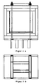
- An embodiment of suitable for carrying out the method clamping device such as FIGS. 1 and 2 shown, has a 2-layer insulation for receiving a high temperature fuel cell stack.
- the insulation material regularly withstands a surface load of ⁇ 1 N / mm 2 without undue deformation.
- the geometry the insulation is adapted to the male high-temperature fuel cell stack.
- clamping plates 1 and 2 are arranged on two opposite sides of the tensioning device, advantageously on a first side with the resource inlets and outlets and the opposite, second side. These should be advantageously carried out as large as the insulation on these sites.
- a clamping frame 3 is arranged with receptacles for standard tie rods 4.
- For a uniform pressure load at least four standard tie rods 4 are provided, which can be adjusted in each case via pressure springs 5 and 6 a hex nut.
- each clamping frame 3 comprises receptacles for four standard tie rods 4, wherein the receptacles are distributed such that there are two each on opposite sides of the particle board 1 and 2 respectively.
- the clamping frame 3 on the first and the (opposite) second side of the clamping device are constructed mirror-symmetrically.
- the location and the number of tie rods 4 substantially corresponds to those of the previously used high temperature resistant special tie rods, except that according to the invention an insulation is provided therebetween.
Landscapes
- Life Sciences & Earth Sciences (AREA)
- Engineering & Computer Science (AREA)
- Manufacturing & Machinery (AREA)
- Sustainable Development (AREA)
- Sustainable Energy (AREA)
- Chemical & Material Sciences (AREA)
- Chemical Kinetics & Catalysis (AREA)
- Electrochemistry (AREA)
- General Chemical & Material Sciences (AREA)
- Fuel Cell (AREA)
Description
- Die Erfindung betrifft ein Verfahren zur Herstellung eines Hochtemperatur-Brennstoffzellenstapels, insbesondere die Verspannung eines Stapels aus planaren Hochtemperatur-Brennstoffzellen (SOFC).
- Eine grundlegende Bedingung für den zuverlässigen Betrieb eines Hochtemperatur-Brennstoffzellenstapels ist die Dichtigkeit der einzelnen Bauteile unter verschiedensten Randbedingungen. Dafür werden die einzelnen Ebenen eines Stapels sowie die dazwischen liegenden Dichtungen, wie beispielsweise Metallfolien, Glimmer, Glaslot oder ähnliches, regelmäßig mechanisch verspannt. An das Verspannen eines Hochtemperatur-Brennstoffzellenstapels im Rahmen der Herstellung und des Betriebs werden aber aufgrund der hohen Betriebstemperaturen von regelmäßig über 700 °C hohe Anforderungen gestellt.
- Aus dem Stand der Technik ist bekannt, die Verspannung eines Hochtemperatur-Brennstoffzellenstapels durch Auflegen einer Last auf den Stapel zu realisieren. Dies führt aber nachteilig zu einer erhöhten Bauweise, zu einem erhöhten Gewicht und oft auch zu erhöhten Kosten.
- Es ist ferner aus dem Stand der Technik bekannt, für die Verspannung eines Hochtemperatur-Brennstoffzellenstapels Zuganker einzusetzen. Diese speziellen, für hohe Temperaturen bis über 1000 °C geeignete Zuganker, weisen häufig einen derartigen thermischen Ausdehnungskoeffizienten auf, dass das Aufheizen des Stapels regelmäßig zu einer definierten und immer stärkeren Verspannung durch den Zuganker führt.
- Die für diesen Einsatz geeigneten Zuganker bestehen nachteilig aus sehr teuren, hochwarmfesten Stählen mit einer sehr geringen Kriechneigung und einem, im Vergleich zu den aus dem Stand der Technik bekannten Stählen für Standardzuganker, niedrigen thermischen Ausdehnungskoeffizienten. Da Kriechen auch bei diesen speziellen Stählen nicht ganz ausgeschlossen werden kann, bleibt dennoch die Gefahr beim Einsatz der speziellen Zuganker, dass ein ausreichend hoher Anpressdruck auf den Stapel über eine längere Zeit nicht immer aufrecht zu erhalten ist.
-
US 5,527,634 A offenbart eine Spannvorrichtung für einen Hochtemperatur-Brennstoffzellenstapel, in dem thermische und elektrische Isolationsplatten oberhalb und unterhalb der Gasverteilungsplatten angeordnet sind. Oberhalb und unterhalb der Isolationsplatten befinden sich Druckplatten, die durch axiale Zuganker verspannt sind. Zusätzlich kann eine thermische Isolationsumhüllung den Zellstapel und die Gasverteilerplatten umgeben. Der Zellstapel kann dabei mittels eines entsprechend temperierten Gasstroms aufgeheizt oder gekühlt werden. - In
US 5,009,968 A wird eine halb steife Isolierung zwischen einem Zellstapel einer Hochtemperatur-Brennstoffzelle und einer Spannvorrichtung offenbart. - Die
JP 10 032016 A - Ferner wird in
EP 0 620 609 A eine Rahmenkonstruktion offenbart, die Teile der Spannvorrichtung integriert. Die Krafteinleitung auf die Druckelemente erfolgt dabei über Zuganker. Isolierplatten dienen zur thermischen und elektrischen Isolierung zwischen dem Zellstapel und den Spannelementen. - Aus
DE 195 06 690 A1 ist eine Spannvorrichtung zum Verspannen von Hochtemperatur-Bauelementen bekannt, bei der zwischen Spannelement und den Hochtemperatur-Bauelementen thermische Isolierelemente angeordnet sind. Bei den Hochtemperatur-Bauelementen handelt es sich insbesondere um stapelförmig angeordnete, bei Temperaturen bis zu 1000 °C arbeitende Hochtemperatur-Brennstoffzellen oder Bauelemente von Hochtemperatur-Brennstoffzellen. - Die Aufgabe der Erfindung ist es, ein Verfahren zur Herstellung eines Hochtemperatur-Brennstoffzellenstapels zu schaffen, bei dem über eine ausreichend lange Zeit eine Verspannung des Stapels unter Betriebsbedingungen erreicht und damit eine sichere Gewährleistung von Dichtigkeit erzielt werden kann. Ferner ist es die Aufgabe der Erfindung eine Vorrichtung zur Durchführung des vorgenannten Verfahrens zur Verfügung zu stellen.
- Die Aufgabe der Erfindung wird gelöst durch ein Verfahren mit der Gesamtheit der Merkmale gemäß Hauptanspruch. Vorteilhafte Ausgestaltungen des Verfahrens ergeben sich aus den darauf rückbezogenen Unteransprüchen.
- Die Aufgabe der Erfindung wird ebenfalls gelöst durch eine Vorrichtung mit der Gesamtheit der Merkmale gemäß Nebenanspruch. Vorteilhafte Ausgestaltungen dieser Vorrichtung finden sich in den auf den Nebenanspruch rückbezogenen Ansprüchen.
- Im Rahmen der Erfindung wurde gefunden, dass auf teure und nicht sicher zuverlässige herkömmliche spezielle Zuganker aus teuren, hochwarmfesten Stählen bei der Verspannung eines Hochtemperatur-Brennstoffzellenstapels verzichtet werden kann, sofern das Aufheizen des Stapels auf Betriebstemperatur innerhalb einer Isolation vorgenommen wird. In einem solchen Fall können vorteilhaft herkömmliche Standardzuganker für die Verspannung des Stapels außerhalb der Isolation verwendet werden.
- Eine dazu geeignete Spann- und Isolationsvorrichtung, im folgenden Spannvorrichtung genannt, umfasst dazu vorteilhaft eine Anschlussplatte, eine den Hochtemperatur-Brennstoffzellenstapel allseitig umschließende, geeignete Isolierung, sowie Mittel zum Verspannen des Stapels, die außerhalb der Isolierung angeordnet sind. Solche geeigneten Mittel zum Verspannen können beispielsweise zwei außerhalb der Isolierung angeordnete Spannplatten mit aufgebrachten Spannrahmen sein, die jeweils Aufnahmen für wenigstens zwei Zuganker aufweisen.
- Eine geeignete Isolierung für einen Hochtemperatur-Brennstoffzellenstapel weist regelmäßig Abmessungen auf, die dem aufzunehmenden Hochtemperatur-Brennstoffzellenstapel entsprechen. Die Isolierung ist vorteilhaft allseitig, d. h. auf allen sechs Seiten des aufzunehmenden Hochtemperatur-Brennstoffzellenstapels vorgesehen. Optional sind für Betriebsmittelzu- und/oder - abführungen, Stromabführungen o. ä. für den Stapel entsprechende Aussparung vorgesehen.
- Die Isolation kann ein- oder mehrlagig ausgestaltet sein, wobei bei mehrlagigen Isolationen gleiche oder auch verschiedene Materialien eingesetzt werden können. Das Material selbst ist dazu geeignet, in der vorgesehenen Weise einen Wärmedurchgang von einem innen angeordneten Hochtemperatur-Brennstoffzellenstapel nach außen regelmäßig zu verhindern. Darunter ist zu verstehen, dass während im Inneren der Isolation der Stapel unter Betriebsbedingungen Temperaturen bis ca. 900 °C aufweist, durch diese Isolation außen beispielsweise nur noch Temperaturen unterhalb von 100 °C vorliegen. Dazu sind insbesondere herkömmliche Hochtemperaturisolierplatten auf Basis von Al2O3 oder auch mikroporöse Dämmstoffe geeignet.
- Das Isolationsmaterial hält ferner regelmäßig Flächenbelastungen von weniger als 1 N/mm2 ohne unzulässige Verformung aus. Dies entspricht dem typischen Anpressdruck, den die Zuganker regelmäßig beim Verspannen auf den Stapel ausüben. Da zwischen den Mitteln zum Verspannen und dem Hochtemperatur-Brennstoffzellenstapel die Isolierung angeordnet ist, muss verhindert werden, dass die Isolation den durch die Mittel aufgebrachten gewünschten Anpressdruck für den Stapel selbst durch Verformung aufnimmt bzw. so deutlich reduziert, dass der effektive Anpressdruck für den Stapel deutlich geringer als der gewünschte Anpressdruck ist. Vorteilhaft sollte das Isolationsmaterial den Anpressdruck nahezu direkt auf den Stapel übertragen.
- Der Vorteil der Erfindung liegt darin, dass die Komponenten der Spannvorrichtung, insbesondere die Mittel zum Verspannen (z. B. Spannrahmen, Zuganker, Anpressfedern, Muttern) durch das Vorsehen einer Isolation einer Einsatztemperatur von regelmäßig unter 100 °C unterliegen, wodurch kostengünstige Standardwerkstoffe und Standardkomponenten einsetzbar sind. Gleichzeitig wird eine zuverlässige und langzeitstabile Verspannung des Stapels erzielt. Das Aufheizen des Stapels auf Betriebstemperatur kann beispielsweise durch innerhalb der Isolierung eingebrachte Heizwendeln oder durch in den Stapel integrierte Heizelemente oder auch durch zuvor aufgeheizte Gase erfolgen.
- Das gesamte Verfahren zum Herstellen, insbesondere zum Verspannen eines Hochtemperatur-Brennstoffzellenstapels mit Hilfe einer zur Durchführung des Verfahrens geeigneten Spannvorrichtung lässt sich beispielsweise wie folgt beschreiben:
- Der Hochtemperatur-Brennstoffzellenstapel wird in einen Ofen eingebracht und durch Auflegen einer Last einem definierten Druck ausgesetzt.
- Während des Aufheizens wird Dichtungsmaterial, beispielsweise Glaslot, aufgeschmolzen und führt zur Abdichtung der Einzelzellen innerhalb des Stapels und des Stapels selbst.
- Der abgekühlte, aber noch unter Druck stehende Stapel, wird behelfsmäßig mit Zugankern, vorteilhaft Standardzuganker inklusive entsprechender Andruckfedern, verspannt und an seinen Einsatzort verbracht.
- Der behelfsmäßig verspannte Stapel wird zunächst auf eine Anschlussplatte oder direkt auf die letzte Zelle eines Brennstoffzellenstapels aufgesetzt und anschließend mit einer Isolation umgeben.
- Die Mittel zum Verspannen des Stapels werden außerhalb der Isolation angeordnet, beispielsweise werden an zwei gegenüberliegenden Seiten Spannplatten mit oder ohne Spannrahmen angebracht, die Aufnahmen für Standardzuganker aufweisen.
- Der Stapel wird mit Hilfe der Mittel zum Verspannen derart verspannt, dass anschließend die behelfsmäßige Verspannung gelöst werden kann. Dazu sind beispielsweise in den oberen zwei Isolierungselementen sowie in der oberen Spannplatte, einschließlich Spannrahmen, Bohrungen vorgesehen. Die behelfsmäßigen Zuganker befinden sich nach dem Anbringen der Isolierung und der Spannplatte innerhalb dieser Bohrungen. Nach dem Verspannen mit der entgültigen Vorrichtung werden diese gelöst und nach oben herausgezogen. Anschließend werden die Bohrungen mit dem entsprechenden Isoliermaterial aufgefüllt.
- Der nunmehr außerhalb der Isolation verspannte Stapel wird auf Betriebstemperatur aufgeheizt.
- Der Einbau des Stapels in die erfindungsgemäße Spannvorrichtung und das Lösen der behelfsmäßigen Verspannung führen zwar zunächst zu einem erhöhten Arbeitsaufwand, aber die sich durch den Einsatz von Standardkomponenten ergebende Kostenersparnis und die Sicherheit einer langzeitstabilen Verspannung des Stapels überwiegen diesen Nachteil deutlich.
- Die im Stand der Technik eingesetzten speziellen, hochwarmfesten Zuganker müssen aus hochwarmfestem Stahl gefertigt werden, deren Temperaturbeständigkeit höher als 1000 °C liegt. Problematisch ist das Ausdehnungsverhalten dieser Stähle. Für die SOFC-Brennstoffzelle werden als Plattenmaterial, ferittische Stähle verwendet, deren Ausdehnungskoeffizient bei ca. 1,3*10-5 l/K liegt. Handelsübliche hochwarmfeste Stähle sind austenitische Stähle mit einem Ausdehnungskoeffizienten, der bei ca. 1,8*10-5 l/K liegt. Diese Art von Stählen ist zum Verspannen ungeeignet, da er sich beim Aufheizen der Brennstoffzelle stärker ausdehnen würde als der Stapel selbst und somit der Verspannung entgegenwirkt. Für diese Anwendung müssen daher speziell entwickelte Stähle verwendet werden. Aus den vorgenannten Gründen ist der Einsatz von Standardkomponenten ein wesentlicher Vorteil dieser Spannvorrichtung.
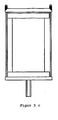
- Nachfolgend wird der Gegenstand der Erfindung anhand von Figuren und einem Ausführungsbeispiel näher erläutert, ohne dass der Gegenstand der Erfindung dadurch beschränkt wird. Es zeigen:
- Figur 1a, b:
- Perspektivische Zeichnung einer zur Durchführung des Verfahrens geeigneten Spannvorrichtung.
- Figur 2a,b,c:
- Ansichtszeichnungen einer zur Durchführung des Verfahrens geeigneten Spannvorrichtung für die drei Raumrichtungen.
-
- 1. obere Spannplatte
- 2. untere Spannplatte
- 3. Spannrahmen
- 4. Zuganker
- 5. Ausdruckfeder
- 6. Sechskantmutter
- 7. Hochtemperatur-Brennstoffzellenstapel
- 8. Anschlussstück
- 9. erste Isolierschicht
- 10. zweite Isolierschicht
- 11. Betriebsmittelzu- bzw. -abführungen
- Eine Ausführungsform der zur Durchführung des Verfahrens geeigneten Spannvorrichtung, wie den
Figuren 1 und2 dargestellt, weist eine 2-lagige Isolierung für die Aufnahme eines Hochtemperatur-Brennstoffzellenstapels auf. Das Isolationsmaterial hält regelmäßig eine Flächenbelastung von < 1 N/mm2 ohne unzulässige Verformung aus. Die Geometrie der Isolation ist an den aufzunehmenden Hochtemperatur-Brennstoffzellenstapel angepasst. - An der Seite des Stapels, an der die Betriebsmittelzu- und/oder -abführungen 11 angeordnet sind, sind entsprechende Durchbrüche in der Isolation vorgesehen.
In dieser Ausführungsform sind an zwei gegenüberliegenden Seiten der Spannvorrichtung, vorteilhaft auf einer ersten Seite mit den Betriebsmittelzu- und -abführungen und der gegenüberliegenden, zweiten Seite, Spannplatten 1 und 2 angeordnet. Diese sollten vorteilhaft so groß wie die Isolation an diesen Seiten ausgeführt werden. Auf diesen Spannplatten ist jeweils ein Spannrahmen 3 mit Aufnahmen für Standardzuganker 4 angeordnet. Für eine gleichmäßige Druckbelastung sind wenigstens vier Standardzuganker 4 vorzusehen, die jeweils über Andruckfedern 5 und eine Sechskantmutter 6 eingestellt werden können.
In diesem Ausführungsbeispiel umfasst jeder Spannrahmen 3 Aufnahmen für vier Standardzuganker 4, wobei die Aufnahmen derart verteilt sind, dass sich je zwei an gegenüberliegenden Seiten der Spanplatte 1 bzw. 2 befinden. Der Spannrahmen 3 auf der ersten und der (gegenüberliegenden) zweiten Seite der Spannvorrichtung sind entsprechend spiegelsymmetrisch aufgebaut. Die Lage und die Anzahl der Zuganker 4 entspricht im wesentlichen denen der bislang eingesetzten hochwarmfesten speziellen Zuganker, davon abgesehen, dass erfindungsgemäß eine Isolation dazwischen vorgesehen ist. Durch gleichmäßiges Verspannen der Standardzuganker werden die gegenüberliegenden Spanplatten mitsamt der dazwischen liegenden Isolation 9 bzw. 10 auf den eingebauten Stapel 7, der gegebenenfalls auf einer Anschlussplatte 8 angeordnet ist, gedrückt und erzeugen so einen möglichst gleichmäßigen Anpressdruck auf den Stapel.
Claims (7)
- Verfahren zur Herstellung eines Hochtemperatur-Brennstoffzellenstapels mit den Schritten:- ein Hochtemperatur-Brennstoffzellenstapel wird durch Auflegen einer Last einem definierten Druck ausgesetzt,- der Hochtemperatur-Brennstoffzellenstapel wird aufgeheizt, wobei Dichtungsmaterial aufgeschmolzen wird und zu einer Abdichtung der Einzelzellen führt,- der Hochtemperatur-Brennstoffzellenstapel wird abgekühlt und mit einem ersten Mittel zum Verspannen verspannt,- der so verspannte Hochtemperatur-Brennstoffzellenstapel wird mit einer Isolation umgeben,- der Hochtemperatur-Brennstoffzellenstapel wird außerhalb der Isolation mit einem zweiten Mittel zum Verspannen verspannt.
- Verfahren nach vorhergehendem Anspruch 1, bei dem der Brennstoffzellenstapel an sechs Seiten mit Isolation umgeben wird.
- Verfahren nach einem der vorhergehenden Ansprüche 1 bis 2, bei dem der Brennstoffzellenstapel mit einer Isolation umgeben wird, die für einen Anpressdruck von weniger als 1 N/mm2 ohne Anzeichen einer Vorformung geeignet ist.
- Verfahren nach einem der vorhergehenden Ansprüche 1 bis 3, bei dem wenigstens zwei Zuganker als Mittel zum Verspannen eingesetzt werden.
- Verfahren nach einem der vorhergehenden Ansprüche 1 bis 4, bei dem nach dem Verspannen mit den zweiten Mitteln zum Verspannen, die ersten Mittel zum Verspannen entfernt werden.
- Verfahren nach einem der vorhergehenden Ansprüche 1 bis 5, bei dem als zweite Mittel zum Verspannen Komponenten eingesetzt werden, die für einen Einsatz bei maximal 150 °C ausgelegt sind.
- Verfahren nach einem der vorhergehenden Ansprüche 1 bis 6, bei dem der mit den ersten Mitteln zum Verspannen verspannte Brennstoffzellenstapel vor dem Verspannen, mit den zweiten Mitteln zum Verspannen, an den Einsatzort des Hochtemperatur-Brenn-stoffzellenstapels verbracht wird
Applications Claiming Priority (3)
| Application Number | Priority Date | Filing Date | Title |
|---|---|---|---|
| DE10308382A DE10308382B3 (de) | 2003-02-27 | 2003-02-27 | Verspannung eines Hochtemperatur-Brennstoffzellenstapels |
| DE10308382 | 2003-02-27 | ||
| PCT/DE2004/000085 WO2004077587A2 (de) | 2003-02-27 | 2004-01-22 | Herstellung eines hochtemperatur-brennstoffzellenstapels |
Publications (2)
| Publication Number | Publication Date |
|---|---|
| EP1597786A2 EP1597786A2 (de) | 2005-11-23 |
| EP1597786B1 true EP1597786B1 (de) | 2008-10-29 |
Family
ID=32920632
Family Applications (1)
| Application Number | Title | Priority Date | Filing Date |
|---|---|---|---|
| EP04704168A Expired - Lifetime EP1597786B1 (de) | 2003-02-27 | 2004-01-22 | Herstellung eines hochtemperatur-brennstoffzellenstapels |
Country Status (5)
| Country | Link |
|---|---|
| EP (1) | EP1597786B1 (de) |
| AT (1) | ATE412983T1 (de) |
| DE (2) | DE10308382B3 (de) |
| DK (1) | DK1597786T3 (de) |
| WO (1) | WO2004077587A2 (de) |
Families Citing this family (19)
| Publication number | Priority date | Publication date | Assignee | Title |
|---|---|---|---|---|
| US7897290B2 (en) | 2004-02-12 | 2011-03-01 | Avl List Gmbh | Device and method for determining the operating parameters of indiviudal cells or short stacks of fuel cells |
| GB2438276B (en) * | 2004-05-13 | 2008-04-16 | Avl List Gmbh | Clamping elements acting on both ends of a fuel cell stack |
| DE102004037678A1 (de) * | 2004-08-02 | 2006-03-16 | Webasto Ag | Brennstoffzellenstapel |
| JP4598510B2 (ja) | 2004-12-22 | 2010-12-15 | 本田技研工業株式会社 | 燃料電池システム |
| US7687172B2 (en) * | 2004-12-22 | 2010-03-30 | Honda Motor Co., Ltd. | Fuel cell system |
| CA2642286A1 (en) * | 2005-02-14 | 2006-08-24 | Gencell Corporation | Fuel cell stack compression assembly |
| DE102006015118B4 (de) * | 2006-03-31 | 2008-09-11 | Enerday Gmbh | Hochtemperatur-Brennstoffzellenstapel, Verfahren zum temporären Verspannen eines HT-Brennstoffzellenstapels, Verfahren zum Entfernen einer temporären Verspannvorrichtung und Verwendung |
| DE102007002286B4 (de) | 2007-01-16 | 2009-01-15 | Enerday Gmbh | Brennstoffzellensystem und Verfahren zu dessen Herstellung |
| DE102007012763B4 (de) | 2007-03-16 | 2014-04-10 | Staxera Gmbh | Gehäuse zum Aufnehmen zumindest eines Brennstoffzellenstapels und Brennstoffzellensystem mit einem solchen Gehäuse |
| DE102007036642A1 (de) | 2007-08-03 | 2009-02-05 | Staxera Gmbh | Verspannung eines Hochtemperaturbrennstoffzellenstacks |
| WO2012040253A1 (en) | 2010-09-20 | 2012-03-29 | Nextech Materials, Ltd. | Fuel cell repeat unit and fuel cell stack |
| DE102011089982B4 (de) * | 2011-12-27 | 2022-03-24 | Bayerische Motoren Werke Aktiengesellschaft | Energiegesamtspeicher |
| DE102012024963B4 (de) | 2012-12-20 | 2023-03-16 | Cellcentric Gmbh & Co. Kg | Brennstoffzellen-Anordnung mit einem geschlossenen Gehäuse |
| FR3066201B1 (fr) * | 2017-05-15 | 2022-01-07 | Commissariat Energie Atomique | Reacteur d'electrolyse ou de co-electrolyse de l'eau (soec) ou pile a combustible (sofc) a fonctionnement sous pression et a systeme de serrage adapte a un tel fonctionnement |
| FR3073093B1 (fr) | 2017-10-26 | 2022-02-04 | Commissariat Energie Atomique | Ensemble d'un empilement a oxydes solides de type soec/sofc et d'un systeme de serrage avec systeme de surchauffe des gaz integre |
| CN112117477A (zh) * | 2019-06-20 | 2020-12-22 | 国家能源投资集团有限责任公司 | 装配结构、电堆阵列及电池系统 |
| FR3129533A1 (fr) * | 2021-11-23 | 2023-05-26 | Commissariat A L'energie Atomique Et Aux Energies Alternatives | Système de conditionnement d’une pluralité d’empilements de cellules à oxydes solides de type SOEC/SOFC à haute température |
| FR3143880B1 (fr) | 2022-12-16 | 2025-10-31 | Symbio France | Pile à combustible et son procédé de fabrication |
| US12385150B1 (en) * | 2025-01-03 | 2025-08-12 | Electric Hydrogen Co. | Compression clamps for electrochemical stacks |
Family Cites Families (9)
| Publication number | Priority date | Publication date | Assignee | Title |
|---|---|---|---|---|
| US4973531A (en) * | 1988-02-19 | 1990-11-27 | Ishikawajima-Harima Heavy Industries Co., Ltd. | Arrangement for tightening stack of fuel cell elements |
| US5009968A (en) * | 1989-09-08 | 1991-04-23 | International Fuel Cells Corporation | Fuel cell end plate structure |
| US5268241A (en) * | 1992-02-20 | 1993-12-07 | Electric Power Research Institute, Inc. | Multiple manifold fuel cell |
| DE4309976A1 (de) * | 1993-03-26 | 1994-09-29 | Daimler Benz Ag | Elektrochemische Mehrzellenbatterie |
| DE19506690A1 (de) * | 1995-02-25 | 1996-08-29 | Licentia Gmbh | Anordnung zur Gaszufuhr für Hochtemperatur-Bauelemente |
| JPH1032016A (ja) * | 1996-07-18 | 1998-02-03 | Ishikawajima Harima Heavy Ind Co Ltd | 燃料電池の締付加熱装置 |
| DE19650904C2 (de) * | 1996-12-07 | 2001-07-26 | Forschungszentrum Juelich Gmbh | Vorrichtung zur Sicherung der mechanischen Integrität eines Brennstoffzellenstapels |
| DE19841919C2 (de) * | 1998-09-12 | 2003-08-14 | Forschungszentrum Juelich Gmbh | Verfahren zur Herstellung eines Brennstoffzellenmoduls |
| DE10003528C2 (de) * | 2000-01-27 | 2002-08-01 | Siemens Ag | Flexibles Zwischenelement und dessen Verwendung |
-
2003
- 2003-02-27 DE DE10308382A patent/DE10308382B3/de not_active Expired - Fee Related
-
2004
- 2004-01-22 EP EP04704168A patent/EP1597786B1/de not_active Expired - Lifetime
- 2004-01-22 DE DE502004008346T patent/DE502004008346D1/de not_active Expired - Lifetime
- 2004-01-22 WO PCT/DE2004/000085 patent/WO2004077587A2/de not_active Ceased
- 2004-01-22 DK DK04704168T patent/DK1597786T3/da active
- 2004-01-22 AT AT04704168T patent/ATE412983T1/de active
Also Published As
| Publication number | Publication date |
|---|---|
| ATE412983T1 (de) | 2008-11-15 |
| WO2004077587A3 (de) | 2005-04-07 |
| DK1597786T3 (da) | 2009-02-23 |
| DE10308382B3 (de) | 2004-11-11 |
| WO2004077587A2 (de) | 2004-09-10 |
| EP1597786A2 (de) | 2005-11-23 |
| DE502004008346D1 (de) | 2008-12-11 |
| WO2004077587A8 (de) | 2005-02-03 |
Similar Documents
| Publication | Publication Date | Title |
|---|---|---|
| DE10308382B3 (de) | Verspannung eines Hochtemperatur-Brennstoffzellenstapels | |
| EP2127010B1 (de) | Isolier- und verspannvorrichtung für eine hochtemperatur-brennstoffzellensystemkomponente | |
| EP0591800A1 (de) | Bauelement zum Einbau in eine verfahrenstechnische Einrichtung | |
| DE10196698B3 (de) | Brennstoffzellenseparator, Herstellungsverfahren desselben, und den Separator verwendende Feststoffpolymerbrennstoffzelle | |
| EP2111668A2 (de) | Medienversorgungsplatte fur einen brennstoffzellenstapel | |
| DE102016004306A1 (de) | Brennstoffzellenstapel, Brennstoffzellensystem, Fahrzeug und Verfahren zum Fertigen eines Brennstoffzellenstapels | |
| DE102021122729A1 (de) | Batteriemodule ohne befestigungselemente | |
| DE102009034141A1 (de) | Gehäuse für eine elektrochemische Vorrichtung | |
| EP1246283B1 (de) | Elektrisch isolierende Abstandshalter/Dichtungsanordnung | |
| DE112006000900T5 (de) | Brennstoffzelle, Verfahren und Vorrichtung zur Herstellung einer Brennstoffzelle | |
| DE3520855C1 (de) | Galvanische Zelle mit Presskontaktierung | |
| DE102017130556B4 (de) | Batterieanordnung | |
| DE102021004963A1 (de) | Vorrichtung zur Verspannung eines Brennstoffzellenstapels oder Elektrolysezellenstapels | |
| DE102017111514B4 (de) | Gehäuse für einen Stapel aus elektrochemischen Einheiten zur Montage in einer elektrochemischen Vorrichtung | |
| EP1652260A2 (de) | Brennstoffzellenanordnung und vorrichtung zum befestigen einer brennstoffzellenanordnung an einem geh use | |
| WO2007112728A1 (de) | Hochtemperatur-brennstoffzellenstapel | |
| EP2174370B1 (de) | Einzel-brennstoffzelle für einen brennstoffzellen-stapel | |
| EP2875546B1 (de) | Spannmittel für einen brennstoffzellenstapel sowie verfahren zum verspannen eines brennstoffzellenstapels | |
| EP1304757A2 (de) | Brennstoffzellenstapel | |
| DE171347T1 (de) | Verfahren zur zufuehrung von elektrolyt einer brennstoffzellenbatterie. | |
| EP4044335A1 (de) | Batteriezelle und verfahren zur herstellung einer batteriezelle | |
| DE10123579A1 (de) | Endplatten und Gehäuse für Brennstoffzellenstacks und deren Herstellung | |
| EP0947026A1 (de) | Brennstoffzellenmodul mit einer gasversorgungseinrichtung | |
| DE202024100156U1 (de) | Elektrochemisches System mit Druckvergleichmäßigungsplatte | |
| DE10250345A1 (de) | Brennstoffzellenanordnung |
Legal Events
| Date | Code | Title | Description |
|---|---|---|---|
| PUAI | Public reference made under article 153(3) epc to a published international application that has entered the european phase |
Free format text: ORIGINAL CODE: 0009012 |
|
| 17P | Request for examination filed |
Effective date: 20050716 |
|
| AK | Designated contracting states |
Kind code of ref document: A2 Designated state(s): AT BE BG CH CY CZ DE DK EE ES FI FR GB GR HU IE IT LI LU MC NL PT RO SE SI SK TR |
|
| AX | Request for extension of the european patent |
Extension state: AL LT LV MK |
|
| DAX | Request for extension of the european patent (deleted) | ||
| GRAP | Despatch of communication of intention to grant a patent |
Free format text: ORIGINAL CODE: EPIDOSNIGR1 |
|
| GRAS | Grant fee paid |
Free format text: ORIGINAL CODE: EPIDOSNIGR3 |
|
| GRAA | (expected) grant |
Free format text: ORIGINAL CODE: 0009210 |
|
| AK | Designated contracting states |
Kind code of ref document: B1 Designated state(s): AT BE BG CH CY CZ DE DK EE ES FI FR GB GR HU IE IT LI LU MC NL PT RO SE SI SK TR |
|
| REG | Reference to a national code |
Ref country code: GB Ref legal event code: FG4D Free format text: NOT ENGLISH |
|
| REG | Reference to a national code |
Ref country code: CH Ref legal event code: EP |
|
| REG | Reference to a national code |
Ref country code: IE Ref legal event code: FG4D Free format text: LANGUAGE OF EP DOCUMENT: GERMAN |
|
| REF | Corresponds to: |
Ref document number: 502004008346 Country of ref document: DE Date of ref document: 20081211 Kind code of ref document: P |
|
| REG | Reference to a national code |
Ref country code: DK Ref legal event code: T3 |
|
| NLV1 | Nl: lapsed or annulled due to failure to fulfill the requirements of art. 29p and 29m of the patents act | ||
| PG25 | Lapsed in a contracting state [announced via postgrant information from national office to epo] |
Ref country code: ES Free format text: LAPSE BECAUSE OF FAILURE TO SUBMIT A TRANSLATION OF THE DESCRIPTION OR TO PAY THE FEE WITHIN THE PRESCRIBED TIME-LIMIT Effective date: 20090209 Ref country code: BG Free format text: LAPSE BECAUSE OF FAILURE TO SUBMIT A TRANSLATION OF THE DESCRIPTION OR TO PAY THE FEE WITHIN THE PRESCRIBED TIME-LIMIT Effective date: 20090129 |
|
| PG25 | Lapsed in a contracting state [announced via postgrant information from national office to epo] |
Ref country code: SI Free format text: LAPSE BECAUSE OF FAILURE TO SUBMIT A TRANSLATION OF THE DESCRIPTION OR TO PAY THE FEE WITHIN THE PRESCRIBED TIME-LIMIT Effective date: 20081029 Ref country code: PT Free format text: LAPSE BECAUSE OF FAILURE TO SUBMIT A TRANSLATION OF THE DESCRIPTION OR TO PAY THE FEE WITHIN THE PRESCRIBED TIME-LIMIT Effective date: 20090330 Ref country code: NL Free format text: LAPSE BECAUSE OF FAILURE TO SUBMIT A TRANSLATION OF THE DESCRIPTION OR TO PAY THE FEE WITHIN THE PRESCRIBED TIME-LIMIT Effective date: 20081029 |
|
| PG25 | Lapsed in a contracting state [announced via postgrant information from national office to epo] |
Ref country code: EE Free format text: LAPSE BECAUSE OF FAILURE TO SUBMIT A TRANSLATION OF THE DESCRIPTION OR TO PAY THE FEE WITHIN THE PRESCRIBED TIME-LIMIT Effective date: 20081029 Ref country code: RO Free format text: LAPSE BECAUSE OF FAILURE TO SUBMIT A TRANSLATION OF THE DESCRIPTION OR TO PAY THE FEE WITHIN THE PRESCRIBED TIME-LIMIT Effective date: 20081029 |
|
| PG25 | Lapsed in a contracting state [announced via postgrant information from national office to epo] |
Ref country code: IT Free format text: LAPSE BECAUSE OF FAILURE TO SUBMIT A TRANSLATION OF THE DESCRIPTION OR TO PAY THE FEE WITHIN THE PRESCRIBED TIME-LIMIT Effective date: 20081029 Ref country code: SE Free format text: LAPSE BECAUSE OF FAILURE TO SUBMIT A TRANSLATION OF THE DESCRIPTION OR TO PAY THE FEE WITHIN THE PRESCRIBED TIME-LIMIT Effective date: 20090129 Ref country code: CZ Free format text: LAPSE BECAUSE OF FAILURE TO SUBMIT A TRANSLATION OF THE DESCRIPTION OR TO PAY THE FEE WITHIN THE PRESCRIBED TIME-LIMIT Effective date: 20081029 |
|
| PLBE | No opposition filed within time limit |
Free format text: ORIGINAL CODE: 0009261 |
|
| STAA | Information on the status of an ep patent application or granted ep patent |
Free format text: STATUS: NO OPPOSITION FILED WITHIN TIME LIMIT |
|
| PG25 | Lapsed in a contracting state [announced via postgrant information from national office to epo] |
Ref country code: SK Free format text: LAPSE BECAUSE OF FAILURE TO SUBMIT A TRANSLATION OF THE DESCRIPTION OR TO PAY THE FEE WITHIN THE PRESCRIBED TIME-LIMIT Effective date: 20081029 |
|
| 26N | No opposition filed |
Effective date: 20090730 |
|
| PG25 | Lapsed in a contracting state [announced via postgrant information from national office to epo] |
Ref country code: GR Free format text: LAPSE BECAUSE OF FAILURE TO SUBMIT A TRANSLATION OF THE DESCRIPTION OR TO PAY THE FEE WITHIN THE PRESCRIBED TIME-LIMIT Effective date: 20090130 |
|
| PGFP | Annual fee paid to national office [announced via postgrant information from national office to epo] |
Ref country code: LU Payment date: 20110124 Year of fee payment: 8 |
|
| PGFP | Annual fee paid to national office [announced via postgrant information from national office to epo] |
Ref country code: MC Payment date: 20110120 Year of fee payment: 8 |
|
| PG25 | Lapsed in a contracting state [announced via postgrant information from national office to epo] |
Ref country code: HU Free format text: LAPSE BECAUSE OF FAILURE TO SUBMIT A TRANSLATION OF THE DESCRIPTION OR TO PAY THE FEE WITHIN THE PRESCRIBED TIME-LIMIT Effective date: 20090430 |
|
| PG25 | Lapsed in a contracting state [announced via postgrant information from national office to epo] |
Ref country code: TR Free format text: LAPSE BECAUSE OF FAILURE TO SUBMIT A TRANSLATION OF THE DESCRIPTION OR TO PAY THE FEE WITHIN THE PRESCRIBED TIME-LIMIT Effective date: 20081029 |
|
| PG25 | Lapsed in a contracting state [announced via postgrant information from national office to epo] |
Ref country code: CY Free format text: LAPSE BECAUSE OF FAILURE TO SUBMIT A TRANSLATION OF THE DESCRIPTION OR TO PAY THE FEE WITHIN THE PRESCRIBED TIME-LIMIT Effective date: 20081029 |
|
| PG25 | Lapsed in a contracting state [announced via postgrant information from national office to epo] |
Ref country code: MC Free format text: LAPSE BECAUSE OF NON-PAYMENT OF DUE FEES Effective date: 20120131 |
|
| PG25 | Lapsed in a contracting state [announced via postgrant information from national office to epo] |
Ref country code: LU Free format text: LAPSE BECAUSE OF NON-PAYMENT OF DUE FEES Effective date: 20120122 |
|
| REG | Reference to a national code |
Ref country code: FR Ref legal event code: PLFP Year of fee payment: 12 |
|
| PGFP | Annual fee paid to national office [announced via postgrant information from national office to epo] |
Ref country code: IE Payment date: 20150123 Year of fee payment: 12 Ref country code: FI Payment date: 20150121 Year of fee payment: 12 Ref country code: DK Payment date: 20150126 Year of fee payment: 12 Ref country code: CH Payment date: 20150123 Year of fee payment: 12 Ref country code: DE Payment date: 20141205 Year of fee payment: 12 |
|
| PGFP | Annual fee paid to national office [announced via postgrant information from national office to epo] |
Ref country code: FR Payment date: 20150115 Year of fee payment: 12 Ref country code: AT Payment date: 20150121 Year of fee payment: 12 Ref country code: GB Payment date: 20150123 Year of fee payment: 12 |
|
| PGFP | Annual fee paid to national office [announced via postgrant information from national office to epo] |
Ref country code: BE Payment date: 20150119 Year of fee payment: 12 |
|
| PG25 | Lapsed in a contracting state [announced via postgrant information from national office to epo] |
Ref country code: BE Free format text: LAPSE BECAUSE OF NON-PAYMENT OF DUE FEES Effective date: 20160131 |
|
| REG | Reference to a national code |
Ref country code: DE Ref legal event code: R119 Ref document number: 502004008346 Country of ref document: DE |
|
| REG | Reference to a national code |
Ref country code: DK Ref legal event code: EBP Effective date: 20160131 |
|
| REG | Reference to a national code |
Ref country code: CH Ref legal event code: PL |
|
| REG | Reference to a national code |
Ref country code: AT Ref legal event code: MM01 Ref document number: 412983 Country of ref document: AT Kind code of ref document: T Effective date: 20160122 |
|
| GBPC | Gb: european patent ceased through non-payment of renewal fee |
Effective date: 20160122 |
|
| REG | Reference to a national code |
Ref country code: FR Ref legal event code: ST Effective date: 20160930 |
|
| PG25 | Lapsed in a contracting state [announced via postgrant information from national office to epo] |
Ref country code: LI Free format text: LAPSE BECAUSE OF NON-PAYMENT OF DUE FEES Effective date: 20160131 Ref country code: DE Free format text: LAPSE BECAUSE OF NON-PAYMENT OF DUE FEES Effective date: 20160802 Ref country code: CH Free format text: LAPSE BECAUSE OF NON-PAYMENT OF DUE FEES Effective date: 20160131 Ref country code: FI Free format text: LAPSE BECAUSE OF NON-PAYMENT OF DUE FEES Effective date: 20160122 Ref country code: GB Free format text: LAPSE BECAUSE OF NON-PAYMENT OF DUE FEES Effective date: 20160122 |
|
| REG | Reference to a national code |
Ref country code: IE Ref legal event code: MM4A |
|
| PG25 | Lapsed in a contracting state [announced via postgrant information from national office to epo] |
Ref country code: AT Free format text: LAPSE BECAUSE OF NON-PAYMENT OF DUE FEES Effective date: 20160122 Ref country code: FR Free format text: LAPSE BECAUSE OF NON-PAYMENT OF DUE FEES Effective date: 20160201 |
|
| PG25 | Lapsed in a contracting state [announced via postgrant information from national office to epo] |
Ref country code: DK Free format text: LAPSE BECAUSE OF NON-PAYMENT OF DUE FEES Effective date: 20160131 Ref country code: IE Free format text: LAPSE BECAUSE OF NON-PAYMENT OF DUE FEES Effective date: 20160122 |