EP1598254A1 - Hängebahn - Google Patents
Hängebahn Download PDFInfo
- Publication number
- EP1598254A1 EP1598254A1 EP05002811A EP05002811A EP1598254A1 EP 1598254 A1 EP1598254 A1 EP 1598254A1 EP 05002811 A EP05002811 A EP 05002811A EP 05002811 A EP05002811 A EP 05002811A EP 1598254 A1 EP1598254 A1 EP 1598254A1
- Authority
- EP
- European Patent Office
- Prior art keywords
- bogie
- rails
- derailment
- box way
- wheels
- Prior art date
- Legal status (The legal status is an assumption and is not a legal conclusion. Google has not performed a legal analysis and makes no representation as to the accuracy of the status listed.)
- Granted
Links
- 239000000725 suspension Substances 0.000 claims abstract description 47
- 230000000712 assembly Effects 0.000 claims abstract description 22
- 238000000429 assembly Methods 0.000 claims abstract description 22
- 238000006073 displacement reaction Methods 0.000 claims abstract description 14
- 239000007787 solid Substances 0.000 claims description 5
- 206010012411 Derailment Diseases 0.000 description 31
- 230000033001 locomotion Effects 0.000 description 16
- 229910000831 Steel Inorganic materials 0.000 description 14
- 239000010959 steel Substances 0.000 description 14
- 230000007246 mechanism Effects 0.000 description 7
- 230000010355 oscillation Effects 0.000 description 7
- 230000008878 coupling Effects 0.000 description 6
- 238000010168 coupling process Methods 0.000 description 6
- 238000005859 coupling reaction Methods 0.000 description 6
- 230000006698 induction Effects 0.000 description 6
- 238000012546 transfer Methods 0.000 description 6
- 230000002159 abnormal effect Effects 0.000 description 4
- 238000011161 development Methods 0.000 description 4
- 238000000034 method Methods 0.000 description 4
- 230000036461 convulsion Effects 0.000 description 3
- 238000007667 floating Methods 0.000 description 3
- 230000000630 rising effect Effects 0.000 description 3
- 206010013710 Drug interaction Diseases 0.000 description 2
- 239000006096 absorbing agent Substances 0.000 description 2
- 230000008901 benefit Effects 0.000 description 2
- 238000006243 chemical reaction Methods 0.000 description 2
- 230000001186 cumulative effect Effects 0.000 description 2
- 238000005516 engineering process Methods 0.000 description 2
- 238000000605 extraction Methods 0.000 description 2
- 238000009434 installation Methods 0.000 description 2
- 230000003993 interaction Effects 0.000 description 2
- 238000005304 joining Methods 0.000 description 2
- 230000035939 shock Effects 0.000 description 2
- 230000004888 barrier function Effects 0.000 description 1
- 238000004891 communication Methods 0.000 description 1
- 238000010276 construction Methods 0.000 description 1
- 230000034994 death Effects 0.000 description 1
- 231100000517 death Toxicity 0.000 description 1
- 230000007423 decrease Effects 0.000 description 1
- 230000003247 decreasing effect Effects 0.000 description 1
- 230000002939 deleterious effect Effects 0.000 description 1
- 230000001419 dependent effect Effects 0.000 description 1
- 238000009826 distribution Methods 0.000 description 1
- 238000005265 energy consumption Methods 0.000 description 1
- 239000000446 fuel Substances 0.000 description 1
- 230000005484 gravity Effects 0.000 description 1
- 239000000383 hazardous chemical Substances 0.000 description 1
- 230000036541 health Effects 0.000 description 1
- 230000006872 improvement Effects 0.000 description 1
- 230000002401 inhibitory effect Effects 0.000 description 1
- 230000009191 jumping Effects 0.000 description 1
- 238000012423 maintenance Methods 0.000 description 1
- 238000007726 management method Methods 0.000 description 1
- 238000004519 manufacturing process Methods 0.000 description 1
- 239000002184 metal Substances 0.000 description 1
- 239000000203 mixture Substances 0.000 description 1
- 238000012986 modification Methods 0.000 description 1
- 230000004048 modification Effects 0.000 description 1
- 230000035515 penetration Effects 0.000 description 1
- 238000005096 rolling process Methods 0.000 description 1
- 230000029305 taxis Effects 0.000 description 1
- 230000007704 transition Effects 0.000 description 1
Images




Classifications
-
- B—PERFORMING OPERATIONS; TRANSPORTING
- B61—RAILWAYS
- B61B—RAILWAY SYSTEMS; EQUIPMENT THEREFOR NOT OTHERWISE PROVIDED FOR
- B61B3/00—Elevated railway systems with suspended vehicles
- B61B3/02—Elevated railway systems with suspended vehicles with self-propelled vehicles
Definitions
- This invention relates to an elevated suspended transportation method and apparatus and devices therefor.
- this invention relates to a transportation system, and more particularly to a system of capable of providing high capacity suspended lateral transportation particularly, in downtown core areas.
- Transportation is a critical element in the smooth and efficient operation of almost every aspect of today's cities and urban areas. All over the world, the population is rising and the infrastructure development is not keeping pace. Roads are unable to handle the rising number of vehicles and metro rails face inadequacies in increasing the capacity, besides there is also the concomitant risk of vandalism and derailment. Expansions or new construction need land in urban areas, which is not possible; alternative underground railways are too expensive. As a result, many types of transportation systems have been developed to move people and cargo from one place to another more efficiently. The most prominent transportation systems are overland travel by cars and bogies, both operating on roads such as public highways. Public buses utilize the same highway network, as do, to some extent, cable cars and electric buses.
- buses also utilize the highway network, but are far less popular than cars. Buses are less favoured than cars because a passenger often has to wait at a bus stop for a relatively long period of time and in potentially disagreeable weather. Further, buses are generally restricted to particular routes, and consequently a bus rider must walk, or acquire other transportation, to and from bus stops along various routes proximate to his origination and destination. Frequently, transfers must be made from one bus to another due to inadequate routes, and frequent interim stops must be made to load or unload other passengers. Still further, buses are subject to many of the same drawbacks as the car, such as traffic, stop lights, and traffic risk. As a result, buses are not as popular as the car even though, when properly utilized, buses are more efficient and less environmentally harmful than the cumulative effect of so many individual cars.
- Rail-guided vehicles such as trains, monorails, metro-rails and subways
- Rail-guided vehicles are an alternative transportation system found in many cities and urban areas. When properly utilized, such systems are more energy efficient than cars and less environmentally damaging.
- rail guided vehicle users are dependent upon predetermined and often inadequate schedules, a limited number of fixed routes, and lost time due to stops at intermediate stations for other passengers. Even the relatively high speeds attained by rail-guided vehicles do not fully compensate for the time lost in other ways when using such transportation systems.
- Surface railway is impossible to lay in an existing city. But even to lay the same in a new development is subject to negative implications. The development remains divided by the corridor and it a permanent noise polluter.
- Underground railway is less invasive on the surface but still poses technical challenges including the management of fires and evacuation. If road vehicles are involved in inter-modal transfers, it becomes a weak link in the chain of transport between walking and the railway.
- Elevated railway technically cannot reach congested central busy roads where mass transport is needed. It is too invasive and may require dislocation of some portions of the habitat as well as the system is very noisy.
- the present invention relates to a public transportation system that fulfills these needs and provides further related advantages.
- An object of the present invention is to provide a more versatile urban transportation system that has hitherto been impossible using systems of the prior art.
- the present invention relates to a novel suspended coach rail transportation system.
- the present invention relates to a means of improving the running and the safety levels of suspended coach rail transportation systems and more specifically, methods, means and devices preventing capsizing of the coach and derailment of the bogie by external forces acting upon the bogie and to provide improved tractive capability.
- the principal objective of the present invention is to provide a suspended coach transportation system that includes a bogie, that can operate inside a continuous box type elevated closed horizontal beam having a slot in lower surface for the traverse of a suspended coach supported by suspenders extending from the beam, that will eliminate the possibility of derailment of the bogie due to forces acting upon the bogie.
- a very high speed 100 KMPH to 200 KMPH, can be obtained.
- a suspended transportation system comprising an extended continuous hollow box way having a slot throughout its operative under wall, said box way being elevated by columns from the ground level and generally following the lay of the ground; a pair of rails fixed on either side of the slot on the operative inner surface of the under wall within the extended box way and extending continuously throughout the box way; a plurality of bogie assemblies moving on the said rails within the box way secured to a floating beam located in the box way operative overhead of the bogie assemblies suspension means extending from the floating beams operatively downwards and through the slot in the box way; removably mounted coaches suspended from suspension means; and motor means to displace the bogie assemblies on the rails.
- the coaches are suspended in the by coach suspension means in a manner that permits controlled longitudinal, swinging and angular displacement of the coaches and their suspension means.
- the box way is a concrete box way and an array of central columns support two extending box ways on either side of the columns permitting traverse of suspended coaches along the box ways on either side and alongside of the columns, typically in opposite directions.
- the box way has a generally rectangular or square cross section defined by a pair of horizontal and a pair of vertical walls typically of concrete said walls enclosing a space; one of said horizontal walls, typically the under wall of the box way defining a continuous slot.
- the extended box way is constructed by aligning and joining a plurality of pre fabricated box way segments secured to the columns.
- the box ways on either side of the columns are integral with each other.
- the columns are typically 1m-diameter columns 8m high spaced apart by a distance of advantageously 15m with respect to each other and formed in the divider space between the carriageways on a roadway.
- the coaches are suspended at a height of 2m to 4m above the road surface/ground level.
- the rails are fitted in an elastic medium dampened by inertia of measured mass.
- the conventional rails used for over ground railways are used as the guiding rails in the box ways.
- an electric current delivering rail is fitted on one of the walls of the box way and running through its length.
- an insulated wheel or other device will run against this power supplying rail effectively collecting current to power motors, preferably linear induction motors cooperating with the bogie assemblies.
- a fourth continuous rail mounted on the inner surface of one of the walls of the box way is provided to cooperate with the linear induction motors associated with the bogie assemblies.
- the bogie is secured to a suspender beam via a connecting steel load transfer beam and spring loaded bolsters, to dampen the jerks and other movements from the rails to the bogie wheels.
- the bogies are also secured to the suspender beams via means of central pivots which permit controlled play and limited angular displacement of the bogie assembly on the suspender beam, if necessary.
- the coaches are suspended from the suspender beam by a plurality of suspender shafts.
- the shafts in accordance with a preferred embodiment of this invention, consist of a plurality of typically four, discreet wire ropes fitted between and spanning the suspender beam joint and the coach roof coupling.
- the suspension shaft is secured to the suspension beam joint by means of cross pins which allow longitudinal motion of the shaft and the coaches suspended therefrom and at the same time the whole arrangement permits the coaches to swing in a controlled manner in an axis parallel to the direction of travel of the coaches.
- the coaches are removably connected the suspension shafts, which permits fast and efficient removal and replacement of the coaches with other coaches or with load carrying. Cargo carrying means, if desired.
- swing control means fitted to the novel suspended coach rail transportation system of this invention.
- the object of this aspect of the invention is to provide a means of improving the safety levels of suspended coach rail transportation systems and more specifically, methods, means and devices controlling the longitudinal swing of the coach and derailment of the bogie by external forces acting upon the bogie and to provide improved tractive capability.
- swing control means in suspension means for coaches in a transportation system consisting of an extended continuous hollow box way having a slot throughout its operative under wall, said box way being elevated by columns from the ground level and generally following the lay of the ground; a pair of rails fixed on either side of the slot on the operative inner surface of the under wall within the extended box way and extending continuously throughout the box way; a plurality of bogie assemblies moving on the said rails within the box way; said coaches being suspended from suspension means extending through the slot in the box way the bogie assemblies being generally connected to the coach suspension means in a manner that permits controlled longitudinal, swinging and angular displacement of the coaches and their suspension means, said swing control means which control the swinging of the coaches beyond a preset limit comprising a plurality of wheels mounted on a space frame swingably secured to the operative roof of the coaches and in the gap between the said roof and the under surface of the said box way, the wheel and frame assembly adapted to swing from a normally inoperative configuration in which the wheels are space
- the controlled swing means in accordance with this invention consist of a set of tyre wheels, typically spring loaded solid rubber tyre wheels fitted on a space frame mounted and spanning between adjacent suspension shafts such that the tyre wheels do not, in its normal operative configuration, touch the box way but in an abnormal operative configuration, if the swing of the coaches goes beyond a preset limit, the wheels will touch and abut the under wall of the box way take the reaction against the under wall of the box way, thereby preventing abnormal swinging.
- the invention relates to a derailment control safety device to be installed on the system in accordance with this invention.
- Another objective of the present invention is to provide in a suspended coach transportation system that includes a bogie, that can operate inside a continuous box type closed horizontal beam having a slot in lower surface for the traverse of the coach body support, that will eliminate the possibility of derailment of the bogie due to forces acting upon the bogie, with or without including devices for controlling excessive swing of the coaches in the stationary state or during motion at high, an improvement in that novel derailment arrester means is provided on the bogie assembly/coach suspension.
- a derailment arrester in a transportation system comprising an extended continuous hollow box way having a slot throughout its operative under wall, said box way being elevated by columns from the ground level and generally following the lay of the ground; a pair of rails fixed on either side of the slot on the operative inner surface of the under wall within the extended box way and extending continuously throughout the box way; a plurality of bogie assemblies moving on the said rails within the box way; removably mounted coaches suspended from suspension means extending through the slot in the box way the bogie assemblies being generally connected to the coach suspension means in a manner that permits controlled longitudinal, swinging and angular displacement of the coaches and their suspension means, said derailment arrester adapted to prevent the displacement of the bogie wheels from the guiding rails consisting of in combination flanges from the running surface of the bogie wheels extending below the outer surface of the rails and a plurality of additional wheels mounted in housings on the suspender beam causing the suspender beam and bogie assembly to bear on the
- This added tractive capability will permit steel wheel cars on steel rails to safely negotiate the gradients commonly encountered in major thoroughfares built for automobiles.
- the second objective of increasing the gradability of the bogie is accomplished by using at least one auxiliary vertical wheel and actuator assembly against the under surface of the roof wall of the box way to create a downward force on the bogie and running wheels providing for additional traction between a smooth steel wheel on a smooth steel rail.
- an objective of the invention is to provide a transit system high slow speed automated people mover suspended coaches which uses at least one anti-derailment wheel as a vertically movable wheel to exert additional vertical reactive force on the two running rails .
- the anti-derailment device used in accordance with this invention is also functional in the inhibiting of vibration caused by the natural frequency of the bogies and the rails being excited by wheel movement by dampening the vibration. Unattenuated vibration creates noise and causes metal fatigue in structures.
- Figure 1 shows a schematic sectional view of a suspended coach transportation system in accordance with this invention.
- the transportation system generally indicated by the reference numeral 10 comprises an extended continuous hollow box way 12 having a slot 14 throughout its operative under wall.
- Columns 16 elevate the box way 10 from the ground level and generally following the lay of the ground.
- a pair of rails 18 are fixed on either side of the slot 14 on the operative inner surface of the under wall within the extended box way 12.
- the rails extend continuously throughout the box way.
- a plurality of bogie assemblies 20 move on the said rails 18 within the box way 12.
- Removably mounted coaches 24 are suspended from suspension means 26 extending through the slot 14 in the box way 12.
- the bogie assemblies 20 are generally connected to the coach suspension means 26 in a manner that permits controlled longitudinal, swinging and angular displacement of the coaches 24 and their suspension means.
- the box way 12 is a concrete box way and an array of central columns 16 support two extending box ways on either side of the columns as seen in Figure 1. These box ways 12 permit traverse of suspended coaches along the box ways on either side and alongside of the columns, typically in opposite directions.
- the box way 12 has a generally rectangular or square cross section defined by a pair of horizontal and a pair of vertical walls typically of concrete said walls enclosing a space; one of said horizontal walls, typically the under wall of the box way defining a continuous slot 14.
- the extended box way is constructed by aligning and joining a plurality of pre fabricated box way segments secured to the columns.
- the box ways on either side of the columns are integral with each other.
- the columns 16 are typically 1m-diameter columns 8m high spaced apart by a distance of advantageously 15m with respect to each other and formed in the divider space between the carriageways on a roadway.
- the coaches 24 are suspended at a height of 2m to 4m above the road surface/ground level.
- the rails 18 are fitted in an elastic medium dampened by inertia of measured mass.
- An electric current delivering rail 27 is fitted on one of the walls of the box way and running through its length. Typically an insulated wheel or other device [not shown] will run against this power supplying rail effectively collecting current to power motors, preferably linear induction motors cooperating with the bogie assemblies.
- a fourth continuous rail 28 mounted on the inner surface of one of the walls of the box way is provided to cooperate with the linear induction motors associated with the bogie assemblies 20 for providing control signals to the bogie assembly motor.
- Figure 3 shows a schematic sectional view of the details of a bogie assembly fitted on the suspender beam.
- Figure 3a shows details of the central pivot joint for the attachment arrangement shown in Figure 3.
- Figure 4 shows the plan view of the bogie assembly partially showing the cooperation between the bogie assembly the suspender beam and the coach.
- Figure 5 shows details of the suspension shaft.
- Figure 6 shows details of the joint between the suspension shaft for the coach and the suspender beam.
- Figure 6 shows the cross pin arrangement at the joint between the suspension shaft and the suspender beam and
- Figure 7 shows the controlled limited movements possible of the suspended coaches.
- the bogie assembly 20 is secured to a suspender beam 30 via a connecting steel load transfer beam 32 and spring loaded bolsters 34, to dampen the jerks and other movements from the rails to the bogie wheels 36.
- the bogies 20 are also secured to the suspender beams 30 via means of central pivots 38 as seen in figure 3a, which permit controlled play, and limited angular displacement of the bogie assembly 20 on the suspender beam 30, if necessary.
- the coaches 24 are suspended from the suspender beam 30 by a plurality of suspender shafts 26 .
- the suspension shaft is secured to the suspension beam 30 joint by means of cross pins 40 as seen in Figure 6 which allow longitudinal motion of the shaft and the coaches suspended therefrom and at the same time the whole arrangement permits the coaches to swing in a controlled manner in an axis parallel to the direction of travel of the coaches.
- the coaches are removably connected the suspension shafts, which permits fast and efficient removal and replacement of the coaches with other coaches or with load carrying. Cargo carrying means, if desired.
- the coaches are coupled to the bogie assemblies indirectly.
- the central pivot type coupling between the bogie assembly and the suspender beam provide controlled limited angular displacement represented by the movement arrows as seen in Figure 4.
- the cross pin type coupling of the suspender shaft and the suspension beam as seen in Figures 6 and 7 permit longitudinal movement across the X-Y plane as seen in Figure 7.
- the coaches are preferably passenger cabins connected indirectly to the bogie assemblies by a rotational coupling that allows the passenger's cabin to remain in the vertical orientation while the attitude of the bogie changes as the direction of the track changes in the vertical direction.
- the coach and bogie configuration is unique in its function of mobility, directional control, track interface, suspension, and flow extraction.
- the track system is also unique in its structural simplicity, universality of application in the transport sphere, and its passive operation. There are no moving track parts for any of the required switching operations.
- the system can operate with a wide range of software trip control packages (headway, trip selection, and stops, individualized priority selection). In most applications the system can utilize proprietary programming software which includes a convoy-like flow.
- a module control and electronic and other services units block assembly 50 is fitted on the suspension beam.
- the system features unique self-propelled multi passenger quick entry/quick exit coaches, which can operate in several different track installations.
- the system can be rapid transit or normal transit type. This type of performance makes the system a true automated Personal Rapid Transit (PRT) system avoiding the use of signals, points, crossings and drivers.
- PRT Personal Rapid Transit
- the self-propelled motion of the coaches can be totally microprocessor based Every new high- density development can provide a new expanded track network to the general public transit system.
- the self-propelled coaches can be made part of the publicly funded transit system; the track network is passive and virtually maintenance-free.
- the market for the system reaches far beyond that of present-day elevated railway technology.
- the scope can quickly widen to fully-fledged transportation system applications, with increasing economies of scale.
- the market scope is further enhanced by the fact that the system can operate a variable mix of passenger coaches and freight cabins.
- coaches passenger and/or freight
- a percentage of coaches can always be operated by the private sector, together with the majority of public transit coaches.
- New techniques of fare collection can preferably be introduced to match the high-efficiency operating characteristics of the system.
- the system is a highly compact full-fledged transport system. Its compactness is a crucial economic factor in future transport planning considerations. Due to its unobtrusive scale and operational silence the system can be tightly integrated with existing facilities. It will be much easier and cheaper to establish this new multi-directional network space, which will largely disappear as part of the road carriageway.
- Present-day transport systems require very substantial right-of-ways and environmentally compromising support structure. Subways and underground railways can cost several bos (currency amount) per kilometer, mostly due to right-of-way costs. In contrast the system would have typical track installation at a fraction of the present day costs.
- the system uses rugged technology of steel wheel on steel rail and uses the standard railway wheel sets and driving mechanism.
- the system can be adapted to any road alignment without disturbing other road traffic. Every minute passengers will get air-condition travel facility, covering distances at more than 45 km/h average speed at just 15 paise per km. Except for providing for right of way on existing roadways. Only at terminal points, minimum amount of land of the order of 2000 to 4000 sqm of area will be required - that too at places away from the urban centre.
- the system is not subject to Vandalism - Not vulnerable to persons throwing stones and track is inaccessible. No demolition of structures or gardens is necessary. No environmental hazards. Fire Protection - Fastest evacuation in case of fire as compared to underground metros No capsizing
- Figure 8 shows schematic sectional view of the details of a swing control mechanism fitted on the suspension shaft of the system of Figure 1.
- Figure 9 shows the schematic view of the space frame for the swing control mechanism shown in Figure 8.
- the controlled swing means in accordance with this invention consist of a set of tyre wheels 60, typically spring loaded solid rubber tyre wheels fitted on a space frame 62 mounted at the same fixture as the suspension means and spanning between adjacent suspension shafts such that the tyre wheels 60 do not, in its normal operative configuration, touch the box way 12 but in an abnormal operative configuration, if the swing of the coaches 24 goes beyond a preset limit, the wheels 60 will touch and abut the under wall of the box way 12 take the reaction against the under wall of the box way , thereby preventing abnormal swinging.
- tyre wheels 60 typically spring loaded solid rubber tyre wheels fitted on a space frame 62 mounted at the same fixture as the suspension means and spanning between adjacent suspension shafts such that the tyre wheels 60 do not, in its normal operative configuration, touch the box way 12 but in an abnormal operative configuration, if the swing of the coaches 24 goes beyond a preset limit, the wheels 60 will touch and abut the under wall of the box way 12 take the
- the coach and bogie configuration is unique in its function of mobility, directional control, track interface, suspension, and flow extraction.
- the swing control mechanism is also unique in its structural simplicity, universality of application in the transport sphere, and its passive operation. There are no moving parts for any of the required operations.
- Figure 10 is the schematic detailed view of the inter action between the steel rails 18 and the steel wheels 21.
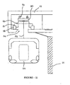
- Figure 11 shows the schematic sectional view of the anti derailment device in accordance with this invention.
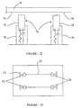
- Figure 12 shows the schematic sectional view of the details of the anti derailment device shown in Figure 11, and
- Figure 13 shows the plan view of the anti derailment device seen in Figure 10.
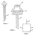
- the profile of the operating surface of the railway wheel is defined by a running surface 'a' and an adjacent flange 'b' typically 8 to 25 inches in length.
- the running surface and the flange are defined by three standardized parameters: flange height flange thickness and rim thickness.
- the Steel Wheel profile includes several sections.
- a flange section protrudes downward from the side of the train wheel and extends over the lateral side of the rail.
- a fillet extends upward along a field side of the flange providing transition to a straight conical wheel tread section.
- the wheel tread section serves as the major load bearing surface that supports the train wheels on the rail.
- the art uses tread profile of two opposing wheel on one of two rails to steer.
- Two opposing wheels are a wheel set.
- the flange provides steering when rail curve exceeds capability of treads to steer without flange contact, which may cause derailment.
- Two main factors have to be considered when designing wheel profiles for use with railed devices.
- the first is the dynamic stability of the suspended coaches and bogie assembly at various speeds throughout its operating speed range. When in transit, a suspended coach train experiences lateral oscillations known as "hunting". Wheel hunting results in the wheels oscillating laterally back and forth between the wheel flanges.
- the maximum speed or critical speed of the bogie assembly is determined by the onset of unstable, undesirable wheel set hunting. For example, if the bogie assembly goes too fast, the force of the lateral oscillations will overcome the flange barrier and cause the bogie assembly to derail.
- Hunting is caused by the dynamics between the wheel tread profile and the rail. Increasing the slope of the wheel tread too fast toward flange increases forces causing hunting and, therefore, lowers the critical speed of the vehicle. Decreasing slope of wheel tread toward flange decreases steering forces, also lowering the critical hunting speed.
- a second factor involved with stability is the ability of the suspended coach to negotiate track curves. This curving ability is determined primarily by the ability of the opposing wheels of a wheel sets to follow the track curves. Optimally, the wheel sets should perform a purely rolling motion in the track curves without any contact between the wheel flanges and the rails. This requires steering forces to be generated by the sloped wheel tread independently of the wheel flange permitting the wheel set to yaw or rotate about a vertical axis which may be through its center. Oscillation of steering forces happen around vertical axis through its center of gravity (mass). This oscillation is a metric space. The oscillation of wheel set results in hunting. The steering forces move the bogie assembly wheel sets into a more radial position with respect to the track curves, thus, increasing bogie assembly stability around curves.
- a wheel set includes two opposite wheels that may be joined together by an axle.
- a conical (straight taper) wheel tread typically as shown in Figure 10
- the conicity remains virtually constant with lateral deflection of a wheel set relative to the rails. That is, straight taper wheel treads have a constant slope.
- the conicity of each wheel remains the same irrespective of whether the wheel set runs centrally on the track or is deflected closer to one rail.
- Increasing the conicity of the wheel tread improves the steering ability of the wheel set because of the increased steering force.
- increased conicity also increases the oscillation of the wheel set. Oscillation of wheel set results in hunting. Therefore, with regard to the conicity of wheel treads, there is a conflict between the requirement for hunting stability and increased speed and for good curving ability of the wheel sets.
- FIG 11 shows a general arrangement of the derailment arrester means 70 typically in the form of solid rubber wheels secured with spring loaded isolator means on the suspender beam 30.
- the typical arrangement scheme is seen in Figure 12 showing the rubber wheels 72 fitted in the isolator spring loaded means 76 which may hydraulic, mechanical or pneumatic and in the form of shock absorbers.
- the gap 'c" between the wheels 72 and the inner surface 74 of the box way is critically set, characterized in that in the normal operation of the movement of the wheel set of the bogie assembly on the rails 18 the derailment arrester wheels 72 will not contact the inner surface 72. Contact will happen only when a turning moment is applied to the wheel set and a jumping of the wheels of the rails 18 is attempted. At this time the wheels 72 will bear on the surface 74 and in turn exert a reactive bearing force on the wheel set and typically the flange portion enforcing contact between the wheel set and the rails 18 and preventing and arresting derailment.
- an electric current delivering rail is fitted on one of the walls of the box way and running through its length and the bogie assemblies are provided with collector means for collecting power from the current delivering rail for operating the motor means .
- the collector means is an insulated wheel which runs against the current delivering rail effectively collecting current to power the motor means.
- the motor means consist of at least one linear induction motors cooperating with the bogie assemblies.
- a fourth continuous rail mounted on the inner surface of one of the walls of the box way is provided to cooperate with the linear induction motors associated with the bogie assemblies for providing remotely located control signals to the motors.
- the coaches are suspended from the suspender beam by coach suspension means in a manner that permits controlled longitudinal, swinging and angular displacement of the coaches and their suspension means.
- the bogie is secured to a floating suspender beam which consist of a connecting steel load transfer beam and the bogie assembly is connected to the transfer beam via spring loaded bolsters, to dampen the jerks and other movements from the rails to the bogie wheels.
- connection between the bogie assembly and the suspender beams is a central pivot which permit controlled play and limited angular displacement of the bogie assembly on the suspender beam.
- the coaches are suspended from the suspender beam by a plurality of suspender shafts consisting of a plurality of typically four, discreet wire ropes fitted between and spanning the suspender beam joint and the coach roof coupling the suspension shaft is secured to the suspension beam joint by means of cross pins which allow longitudinal motion of the shaft and the coaches suspended therefrom and at the same time the whole arrangement permits the coaches to swing in a controlled manner in an axis parallel to the direction of travel of the coaches.
- the coaches are removably connected the suspension shafts, which permits fast and efficient removal and replacement of the coaches with other coaches or with load carrying cargo carrying means.
- the additional wheels are spring loaded.
- additional wheels are solid rubber wheels.
- the additional wheels are spaced apart from the under surface of the top wall of the concrete box way.
Landscapes
- Engineering & Computer Science (AREA)
- Transportation (AREA)
- Mechanical Engineering (AREA)
- Platform Screen Doors And Railroad Systems (AREA)
- Carriers, Traveling Bodies, And Overhead Traveling Cranes (AREA)
- Two-Way Televisions, Distribution Of Moving Picture Or The Like (AREA)
- Paper (AREA)
Applications Claiming Priority (7)
| Application Number | Priority Date | Filing Date | Title |
|---|---|---|---|
| INMU07172001 | 2001-07-26 | ||
| IN716MU2001 | 2001-07-26 | ||
| IN717MU2001 | 2001-07-26 | ||
| INMU07162001 | 2001-07-26 | ||
| IN715MU2001 | 2001-07-26 | ||
| INMU07152001 | 2001-07-26 | ||
| EP02255243A EP1279579B1 (de) | 2001-07-26 | 2002-07-26 | Hängebahn |
Related Parent Applications (2)
| Application Number | Title | Priority Date | Filing Date |
|---|---|---|---|
| EP02255243A Division EP1279579B1 (de) | 2001-07-26 | 2002-07-26 | Hängebahn |
| EP02255243.4 Division | 2002-07-26 |
Publications (2)
| Publication Number | Publication Date |
|---|---|
| EP1598254A1 true EP1598254A1 (de) | 2005-11-23 |
| EP1598254B1 EP1598254B1 (de) | 2011-04-20 |
Family
ID=27272464
Family Applications (2)
| Application Number | Title | Priority Date | Filing Date |
|---|---|---|---|
| EP02255243A Expired - Lifetime EP1279579B1 (de) | 2001-07-26 | 2002-07-26 | Hängebahn |
| EP05002811A Expired - Lifetime EP1598254B1 (de) | 2001-07-26 | 2002-07-26 | Hängebahn |
Family Applications Before (1)
| Application Number | Title | Priority Date | Filing Date |
|---|---|---|---|
| EP02255243A Expired - Lifetime EP1279579B1 (de) | 2001-07-26 | 2002-07-26 | Hängebahn |
Country Status (4)
| Country | Link |
|---|---|
| US (1) | US6688235B2 (de) |
| EP (2) | EP1279579B1 (de) |
| AT (2) | ATE506234T1 (de) |
| DE (2) | DE60226814D1 (de) |
Cited By (1)
| Publication number | Priority date | Publication date | Assignee | Title |
|---|---|---|---|---|
| RU2464188C2 (ru) * | 2010-12-02 | 2012-10-20 | Валерий Евгеньевич Чигинёв | Подвесная транспортная система |
Families Citing this family (27)
| Publication number | Priority date | Publication date | Assignee | Title |
|---|---|---|---|---|
| US7124692B2 (en) * | 2002-10-15 | 2006-10-24 | Sky Train Corporation | Overhead suspended transportation system and method |
| US20070017410A1 (en) * | 2003-10-14 | 2007-01-25 | Sky Train Corporation | Overhead Suspended Transportation System and Method |
| BRPI0402777A (pt) * | 2004-07-16 | 2006-03-01 | Luiz Augusto De Siqueira Costa | veìculo monotrilho e sistema de transporte monotrilho |
| WO2010023500A1 (en) * | 2008-08-24 | 2010-03-04 | Rajaram Bojji | Gravity powered rail, road and runway transportation system |
| US8375865B2 (en) * | 2010-09-03 | 2013-02-19 | Jose Alberto Zayas | Overhead suspended personal transportation and freight delivery surface transportation system |
| CN102463997A (zh) * | 2010-11-15 | 2012-05-23 | 盐城海旭数控装备有限公司 | 一种悬挂式新能源轨道公交车 |
| CN102463994B (zh) * | 2010-11-15 | 2014-11-12 | 盐城海旭数控装备有限公司 | 一种双层双向路轨兼容绿色公交系统 |
| US20130302118A1 (en) * | 2011-01-21 | 2013-11-14 | Siemens Aktiengesellschaft | Method for handling baggage within airport and system thereof |
| CN102730003B (zh) * | 2011-04-15 | 2015-07-15 | 盐城海旭数控装备有限公司 | 一种双层双向路轨兼容绿色公交系统回车台 |
| ITBZ20110055A1 (it) * | 2011-11-14 | 2013-05-15 | Hans Costabiei | Sistema di percorso in curva, di incrocio e di deviazione per impianti a fune con veicoli semoventi a motori elettrici lineari |
| US20140130700A1 (en) * | 2012-11-14 | 2014-05-15 | Swift Tram, Inc. | Suspended coach drive bogie |
| CN103010219A (zh) * | 2012-11-26 | 2013-04-03 | 河南重工起重机集团有限公司 | 用于旅客运输的改进型空中轨道交通系统 |
| CN105377663B (zh) * | 2013-05-16 | 2019-10-22 | 富特兰有限公司 | 轨道交通转向架和轨道交通系统 |
| CN106364490B (zh) * | 2014-09-17 | 2019-01-29 | 张向东 | 一种列车轨道及列车系统 |
| CN108657986B (zh) * | 2017-03-31 | 2024-01-23 | 中铁华铁工程设计集团有限公司 | 悬挂式单轨车辆检修用移动平台 |
| CN108382404A (zh) * | 2018-03-21 | 2018-08-10 | 段绪松 | 一种新型城市轨道交通系统 |
| CN108327729B (zh) * | 2018-04-04 | 2024-03-29 | 中唐空铁集团有限公司 | 一种空铁系统 |
| CN109131370B (zh) * | 2018-08-06 | 2019-06-21 | 江西理工大学 | 悬挂式磁悬浮轨道交通系统 |
| CN110565455B (zh) * | 2019-10-09 | 2024-08-30 | 中建空列(北京)科技有限公司 | 行驶辅助牵引车及系统 |
| CN111137779A (zh) * | 2020-01-16 | 2020-05-12 | 湖南汇捷智能装备有限公司 | 一种带浮动梁的集装箱吊具 |
| US11299182B2 (en) | 2020-06-02 | 2022-04-12 | Jean Victor Peloquin | Suspended public transit system |
| CN112195749B (zh) * | 2020-09-21 | 2025-02-28 | 中铁第四勘察设计院集团有限公司 | 用于悬挂式单轨交通的轨道梁以及悬挂式单轨交通桥梁 |
| CN114312863B (zh) * | 2020-09-29 | 2024-11-15 | 中冶京诚工程技术有限公司 | 跨悬式轨道交通车辆及轨道交通系统 |
| CN114352465B (zh) * | 2021-12-30 | 2025-07-25 | 毛秀伟 | 波浪能发电装置 |
| JP7480797B2 (ja) * | 2022-03-14 | 2024-05-10 | 村田機械株式会社 | 天井搬送車システム |
| CN117601916A (zh) * | 2023-10-18 | 2024-02-27 | 广东京兰空铁发展有限公司 | 连接装置、悬吊系统及空铁列车 |
| USD1121180S1 (en) | 2024-02-15 | 2026-03-31 | American Polymer Company | Utility access box |
Citations (3)
| Publication number | Priority date | Publication date | Assignee | Title |
|---|---|---|---|---|
| US2020540A (en) * | 1934-03-14 | 1935-11-12 | Dunlap De Clermont | Monorail motor truck |
| US2825291A (en) | 1952-12-18 | 1958-03-04 | Gestion Et D Entpr S Sa Franc | Overhead urban railway |
| EP0734930A1 (de) | 1995-03-29 | 1996-10-02 | Paul Glassey | Schwebebahn-Transportsystem mit Schienen |
Family Cites Families (9)
| Publication number | Priority date | Publication date | Assignee | Title |
|---|---|---|---|---|
| US1355801A (en) * | 1918-06-24 | 1920-10-12 | Nat Suspended Monorail Company | Suspended monorail system |
| FR1237295A (fr) * | 1959-06-18 | 1960-07-29 | Usine Paulstra | Perfectionnements apportés aux installations du genre des chemins de fer suspendus |
| FR1238872A (fr) * | 1959-07-07 | 1960-08-19 | Alsthom Cgee | Bogie pour chemin de fer suspendu |
| US3225228A (en) * | 1963-10-10 | 1965-12-21 | John L Roshala | Linear magnetic drive system |
| GB1192417A (en) * | 1967-04-10 | 1970-05-20 | Safege Transp | Improvements in or relating to Overhead Railways |
| US3774542A (en) * | 1971-10-20 | 1973-11-27 | R Walsh | Transportation system |
| US3847085A (en) * | 1973-07-16 | 1974-11-12 | Duo Mode Electric Trans Syst | Dual-mode transportation system |
| DE2530216A1 (de) * | 1975-07-07 | 1977-02-03 | Dieter Schempp | Zwangsgefuehrte schnellbahn |
| DE19508719A1 (de) * | 1995-03-10 | 1996-09-12 | Siemens Ag | Hängebahnkabine |
-
2002
- 2002-07-26 US US10/206,311 patent/US6688235B2/en not_active Expired - Fee Related
- 2002-07-26 DE DE60226814T patent/DE60226814D1/de not_active Expired - Fee Related
- 2002-07-26 AT AT05002811T patent/ATE506234T1/de not_active IP Right Cessation
- 2002-07-26 AT AT02255243T patent/ATE396896T1/de not_active IP Right Cessation
- 2002-07-26 EP EP02255243A patent/EP1279579B1/de not_active Expired - Lifetime
- 2002-07-26 EP EP05002811A patent/EP1598254B1/de not_active Expired - Lifetime
- 2002-07-26 DE DE60239834T patent/DE60239834D1/de not_active Expired - Lifetime
Patent Citations (3)
| Publication number | Priority date | Publication date | Assignee | Title |
|---|---|---|---|---|
| US2020540A (en) * | 1934-03-14 | 1935-11-12 | Dunlap De Clermont | Monorail motor truck |
| US2825291A (en) | 1952-12-18 | 1958-03-04 | Gestion Et D Entpr S Sa Franc | Overhead urban railway |
| EP0734930A1 (de) | 1995-03-29 | 1996-10-02 | Paul Glassey | Schwebebahn-Transportsystem mit Schienen |
Cited By (1)
| Publication number | Priority date | Publication date | Assignee | Title |
|---|---|---|---|---|
| RU2464188C2 (ru) * | 2010-12-02 | 2012-10-20 | Валерий Евгеньевич Чигинёв | Подвесная транспортная система |
Also Published As
| Publication number | Publication date |
|---|---|
| EP1598254B1 (de) | 2011-04-20 |
| ATE396896T1 (de) | 2008-06-15 |
| US6688235B2 (en) | 2004-02-10 |
| DE60226814D1 (de) | 2008-07-10 |
| EP1279579A1 (de) | 2003-01-29 |
| DE60239834D1 (de) | 2011-06-01 |
| ATE506234T1 (de) | 2011-05-15 |
| US20030047106A1 (en) | 2003-03-13 |
| EP1279579B1 (de) | 2008-05-28 |
Similar Documents
| Publication | Publication Date | Title |
|---|---|---|
| US6688235B2 (en) | Suspended coach transportation system | |
| JP5330836B2 (ja) | 車輌用ライン | |
| US4690064A (en) | Side-mounted monorail transportation system | |
| US5456183A (en) | Integrated infrastructure transit system | |
| US20040250724A1 (en) | Multipurpose vehicle for various types of travel ways | |
| US8950337B1 (en) | Personal transportation rail system | |
| CN107839696B (zh) | 一种永磁轴式直驱空地共享立体快速轨道交通系统 | |
| US7124692B2 (en) | Overhead suspended transportation system and method | |
| CN112519804B (zh) | 一种悬挂式混合磁悬浮轨道交通系统 | |
| US11364940B1 (en) | Adaptive route rail system with passive switches | |
| US20240376675A1 (en) | rail structure of steel rail track and steel wheel vehicle | |
| KR100864413B1 (ko) | 모노레일 운행 시스템 | |
| JP2025502975A5 (de) | ||
| CN109878544B (zh) | 一种用于旅游景区的轨道车辆转向架总成及轨交系统 | |
| RU2145557C1 (ru) | Монорельсовая транспортная система навесного типа | |
| RU2158211C1 (ru) | Монорельсовая транспортная система конвертируемого типа | |
| EP1279580B1 (de) | Hängebahn | |
| US20060162609A1 (en) | Interstate highway train system | |
| JP2006327533A (ja) | 鉄道車両用登坂性向上装置 | |
| CN109572719B (zh) | 一种侧挂式高架轨道交通道岔系统 | |
| US20070017410A1 (en) | Overhead Suspended Transportation System and Method | |
| US20230339273A1 (en) | Adaptive Route Rail System Using Passive Switches | |
| GB2348410A (en) | Hanging railway system | |
| JP2000171479A (ja) | 車輛の姿勢を規制する軌条を有した輸送機構の高速化 | |
| CN118786267A (zh) | 钢轨铁路钢轮火车的运动机构 |
Legal Events
| Date | Code | Title | Description |
|---|---|---|---|
| PUAI | Public reference made under article 153(3) epc to a published international application that has entered the european phase |
Free format text: ORIGINAL CODE: 0009012 |
|
| 17P | Request for examination filed |
Effective date: 20050308 |
|
| AC | Divisional application: reference to earlier application |
Ref document number: 1279579 Country of ref document: EP Kind code of ref document: P |
|
| AK | Designated contracting states |
Kind code of ref document: A1 Designated state(s): AT BE BG CH CY CZ DE DK EE ES FI FR GB GR IE IT LI LU MC NL PT SE SK TR |
|
| RTI1 | Title (correction) |
Free format text: A SUSPENDED VEHICLES TRANSPORTATION SYSTEM |
|
| AKX | Designation fees paid |
Designated state(s): AT BE BG CH CY CZ DE DK EE ES FI FR GB GR IE IT LI LU MC NL PT SE SK TR |
|
| 17Q | First examination report despatched |
Effective date: 20070822 |
|
| GRAP | Despatch of communication of intention to grant a patent |
Free format text: ORIGINAL CODE: EPIDOSNIGR1 |
|
| GRAS | Grant fee paid |
Free format text: ORIGINAL CODE: EPIDOSNIGR3 |
|
| GRAA | (expected) grant |
Free format text: ORIGINAL CODE: 0009210 |
|
| AC | Divisional application: reference to earlier application |
Ref document number: 1279579 Country of ref document: EP Kind code of ref document: P |
|
| AK | Designated contracting states |
Kind code of ref document: B1 Designated state(s): AT BE BG CH CY CZ DE DK EE ES FI FR GB GR IE IT LI LU MC NL PT SE SK TR |
|
| REG | Reference to a national code |
Ref country code: GB Ref legal event code: FG4D |
|
| REG | Reference to a national code |
Ref country code: CH Ref legal event code: EP |
|
| REG | Reference to a national code |
Ref country code: IE Ref legal event code: FG4D |
|
| REF | Corresponds to: |
Ref document number: 60239834 Country of ref document: DE Date of ref document: 20110601 Kind code of ref document: P |
|
| REG | Reference to a national code |
Ref country code: DE Ref legal event code: R096 Ref document number: 60239834 Country of ref document: DE Effective date: 20110601 |
|
| REG | Reference to a national code |
Ref country code: NL Ref legal event code: VDEP Effective date: 20110420 |
|
| PG25 | Lapsed in a contracting state [announced via postgrant information from national office to epo] |
Ref country code: SE Free format text: LAPSE BECAUSE OF FAILURE TO SUBMIT A TRANSLATION OF THE DESCRIPTION OR TO PAY THE FEE WITHIN THE PRESCRIBED TIME-LIMIT Effective date: 20110420 Ref country code: PT Free format text: LAPSE BECAUSE OF FAILURE TO SUBMIT A TRANSLATION OF THE DESCRIPTION OR TO PAY THE FEE WITHIN THE PRESCRIBED TIME-LIMIT Effective date: 20110822 |
|
| PG25 | Lapsed in a contracting state [announced via postgrant information from national office to epo] |
Ref country code: FI Free format text: LAPSE BECAUSE OF FAILURE TO SUBMIT A TRANSLATION OF THE DESCRIPTION OR TO PAY THE FEE WITHIN THE PRESCRIBED TIME-LIMIT Effective date: 20110420 Ref country code: AT Free format text: LAPSE BECAUSE OF FAILURE TO SUBMIT A TRANSLATION OF THE DESCRIPTION OR TO PAY THE FEE WITHIN THE PRESCRIBED TIME-LIMIT Effective date: 20110420 Ref country code: BE Free format text: LAPSE BECAUSE OF FAILURE TO SUBMIT A TRANSLATION OF THE DESCRIPTION OR TO PAY THE FEE WITHIN THE PRESCRIBED TIME-LIMIT Effective date: 20110420 Ref country code: CY Free format text: LAPSE BECAUSE OF FAILURE TO SUBMIT A TRANSLATION OF THE DESCRIPTION OR TO PAY THE FEE WITHIN THE PRESCRIBED TIME-LIMIT Effective date: 20110420 Ref country code: GR Free format text: LAPSE BECAUSE OF FAILURE TO SUBMIT A TRANSLATION OF THE DESCRIPTION OR TO PAY THE FEE WITHIN THE PRESCRIBED TIME-LIMIT Effective date: 20110721 Ref country code: ES Free format text: LAPSE BECAUSE OF FAILURE TO SUBMIT A TRANSLATION OF THE DESCRIPTION OR TO PAY THE FEE WITHIN THE PRESCRIBED TIME-LIMIT Effective date: 20110731 |
|
| PG25 | Lapsed in a contracting state [announced via postgrant information from national office to epo] |
Ref country code: NL Free format text: LAPSE BECAUSE OF FAILURE TO SUBMIT A TRANSLATION OF THE DESCRIPTION OR TO PAY THE FEE WITHIN THE PRESCRIBED TIME-LIMIT Effective date: 20110420 |
|
| PG25 | Lapsed in a contracting state [announced via postgrant information from national office to epo] |
Ref country code: CZ Free format text: LAPSE BECAUSE OF FAILURE TO SUBMIT A TRANSLATION OF THE DESCRIPTION OR TO PAY THE FEE WITHIN THE PRESCRIBED TIME-LIMIT Effective date: 20110420 Ref country code: EE Free format text: LAPSE BECAUSE OF FAILURE TO SUBMIT A TRANSLATION OF THE DESCRIPTION OR TO PAY THE FEE WITHIN THE PRESCRIBED TIME-LIMIT Effective date: 20110420 |
|
| PLBE | No opposition filed within time limit |
Free format text: ORIGINAL CODE: 0009261 |
|
| STAA | Information on the status of an ep patent application or granted ep patent |
Free format text: STATUS: NO OPPOSITION FILED WITHIN TIME LIMIT |
|
| PG25 | Lapsed in a contracting state [announced via postgrant information from national office to epo] |
Ref country code: SK Free format text: LAPSE BECAUSE OF FAILURE TO SUBMIT A TRANSLATION OF THE DESCRIPTION OR TO PAY THE FEE WITHIN THE PRESCRIBED TIME-LIMIT Effective date: 20110420 Ref country code: MC Free format text: LAPSE BECAUSE OF NON-PAYMENT OF DUE FEES Effective date: 20110731 Ref country code: DK Free format text: LAPSE BECAUSE OF FAILURE TO SUBMIT A TRANSLATION OF THE DESCRIPTION OR TO PAY THE FEE WITHIN THE PRESCRIBED TIME-LIMIT Effective date: 20110420 |
|
| REG | Reference to a national code |
Ref country code: CH Ref legal event code: PL |
|
| 26N | No opposition filed |
Effective date: 20120123 |
|
| REG | Reference to a national code |
Ref country code: FR Ref legal event code: ST Effective date: 20120330 |
|
| REG | Reference to a national code |
Ref country code: IE Ref legal event code: MM4A |
|
| PG25 | Lapsed in a contracting state [announced via postgrant information from national office to epo] |
Ref country code: DE Free format text: LAPSE BECAUSE OF NON-PAYMENT OF DUE FEES Effective date: 20120201 Ref country code: LI Free format text: LAPSE BECAUSE OF NON-PAYMENT OF DUE FEES Effective date: 20110731 Ref country code: CH Free format text: LAPSE BECAUSE OF NON-PAYMENT OF DUE FEES Effective date: 20110731 Ref country code: FR Free format text: LAPSE BECAUSE OF NON-PAYMENT OF DUE FEES Effective date: 20110801 |
|
| REG | Reference to a national code |
Ref country code: DE Ref legal event code: R119 Ref document number: 60239834 Country of ref document: DE Effective date: 20120201 |
|
| REG | Reference to a national code |
Ref country code: DE Ref legal event code: R097 Ref document number: 60239834 Country of ref document: DE Effective date: 20120123 |
|
| PG25 | Lapsed in a contracting state [announced via postgrant information from national office to epo] |
Ref country code: IT Free format text: LAPSE BECAUSE OF FAILURE TO SUBMIT A TRANSLATION OF THE DESCRIPTION OR TO PAY THE FEE WITHIN THE PRESCRIBED TIME-LIMIT Effective date: 20110420 |
|
| PG25 | Lapsed in a contracting state [announced via postgrant information from national office to epo] |
Ref country code: IE Free format text: LAPSE BECAUSE OF NON-PAYMENT OF DUE FEES Effective date: 20110726 |
|
| PGFP | Annual fee paid to national office [announced via postgrant information from national office to epo] |
Ref country code: GB Payment date: 20120724 Year of fee payment: 11 |
|
| PG25 | Lapsed in a contracting state [announced via postgrant information from national office to epo] |
Ref country code: LU Free format text: LAPSE BECAUSE OF NON-PAYMENT OF DUE FEES Effective date: 20110726 |
|
| PG25 | Lapsed in a contracting state [announced via postgrant information from national office to epo] |
Ref country code: BG Free format text: LAPSE BECAUSE OF FAILURE TO SUBMIT A TRANSLATION OF THE DESCRIPTION OR TO PAY THE FEE WITHIN THE PRESCRIBED TIME-LIMIT Effective date: 20110720 |
|
| PG25 | Lapsed in a contracting state [announced via postgrant information from national office to epo] |
Ref country code: TR Free format text: LAPSE BECAUSE OF FAILURE TO SUBMIT A TRANSLATION OF THE DESCRIPTION OR TO PAY THE FEE WITHIN THE PRESCRIBED TIME-LIMIT Effective date: 20110420 |
|
| GBPC | Gb: european patent ceased through non-payment of renewal fee |
Effective date: 20130726 |
|
| PG25 | Lapsed in a contracting state [announced via postgrant information from national office to epo] |
Ref country code: GB Free format text: LAPSE BECAUSE OF NON-PAYMENT OF DUE FEES Effective date: 20130726 |