EP1598446A2 - Procédé et dispositif de détection de corrosion par courant alternatif dans des installations ayant une protection cathodique - Google Patents
Procédé et dispositif de détection de corrosion par courant alternatif dans des installations ayant une protection cathodique Download PDFInfo
- Publication number
- EP1598446A2 EP1598446A2 EP05008456A EP05008456A EP1598446A2 EP 1598446 A2 EP1598446 A2 EP 1598446A2 EP 05008456 A EP05008456 A EP 05008456A EP 05008456 A EP05008456 A EP 05008456A EP 1598446 A2 EP1598446 A2 EP 1598446A2
- Authority
- EP
- European Patent Office
- Prior art keywords
- electrode
- corrosion
- electrolyte
- electrical
- cathodically protected
- Prior art date
- Legal status (The legal status is an assumption and is not a legal conclusion. Google has not performed a legal analysis and makes no representation as to the accuracy of the status listed.)
- Withdrawn
Links
Images


Classifications
-
- G—PHYSICS
- G01—MEASURING; TESTING
- G01N—INVESTIGATING OR ANALYSING MATERIALS BY DETERMINING THEIR CHEMICAL OR PHYSICAL PROPERTIES
- G01N17/00—Investigating resistance of materials to the weather, to corrosion, or to light
- G01N17/02—Electrochemical measuring systems for weathering, corrosion or corrosion-protection measurement
-
- C—CHEMISTRY; METALLURGY
- C23—COATING METALLIC MATERIAL; COATING MATERIAL WITH METALLIC MATERIAL; CHEMICAL SURFACE TREATMENT; DIFFUSION TREATMENT OF METALLIC MATERIAL; COATING BY VACUUM EVAPORATION, BY SPUTTERING, BY ION IMPLANTATION OR BY CHEMICAL VAPOUR DEPOSITION, IN GENERAL; INHIBITING CORROSION OF METALLIC MATERIAL OR INCRUSTATION IN GENERAL
- C23F—NON-MECHANICAL REMOVAL OF METALLIC MATERIAL FROM SURFACE; INHIBITING CORROSION OF METALLIC MATERIAL OR INCRUSTATION IN GENERAL; MULTI-STEP PROCESSES FOR SURFACE TREATMENT OF METALLIC MATERIAL INVOLVING AT LEAST ONE PROCESS PROVIDED FOR IN CLASS C23 AND AT LEAST ONE PROCESS COVERED BY SUBCLASS C21D OR C22F OR CLASS C25
- C23F13/00—Inhibiting corrosion of metals by anodic or cathodic protection
- C23F13/02—Inhibiting corrosion of metals by anodic or cathodic protection cathodic; Selection of conditions, parameters or procedures for cathodic protection, e.g. of electrical conditions
- C23F13/04—Controlling or regulating desired parameters
Definitions
- the present invention relates to a method and an arrangement for Acquisition of AC corrosion on cathodically protected equipment, with a to be examined section of the plant contains a corrodible material which reacts when AC corrosion occurs to a corrosion product.
- cathodic corrosion protection By cathodic corrosion protection, buried pipelines and other installations in corrosive environment, known to be protected against corrosion. However, induced AC voltage in the systems may cause it cathodic corrosion protection come to AC corrosion.
- the control of buried facilities for corrosion is problematic. This is mainly due to the unfavorable accessibility of the plants to be protected. It is a method of determining the pipeline bottom potential at cathodic protected pipelines, where at different Measuring points along a pipeline a reference electrode above the pipeline is placed on the ground (DE 100 21 994 A1 - Method of determination of the tube / ground potential on cathodically protected pipelines). This Method is for the detection and quantitative detection of AC corrosion but not suitable.
- potential measurements on the coupons are in the form of so-called High-speed measurements known.
- the coupons are from the pipeline electrically decoupled, and the potential of the coupon is immediately after the Separation against a standard potential measured.
- Object of the present invention is to provide a detection and quantitative Acquisition of AC corrosion on cathodically protected installations improve.
- this object is achieved in that from a portion of the cathodically protected system, a first electrode is formed, which contains a quantity of the corrosion product and the first electrode via an electrolyte with at least one further electrode in electrolyte compound is brought in that an electrical voltage is applied between the first and the at least one further electrode in order to initiate an electrochemical reaction, wherein the corrosion product of the first electrode participates in the electrochemical reaction and is converted to a reaction product, that the course of the reaction is controlled by adjusting at least one electrical quantity at the electrodes, that at least one electrical measured quantity is detected from a group of measured variables consisting of current intensity, potential difference and charge, and the amount of the corrosion product reacted in the reaction is determined from the at least one electrical measured variable.
- the object is further according to the invention by an arrangement according to Claim 14 solved.
- the selection of the electrical voltage source may vary according to the circumstances Site and the desired measurement times are taken. The measured quantities must draw conclusions on the type and / or quantity of the implemented Allow corrosion product.
- electric power or Voltage sources in the form of a galvanostat, a potentiostat, a battery or a DC power supply.
- a galvanostat For example, a corrosion product may be at a given regulated current to be implemented, taking care to maintain the amperage required voltage is measured. From the amperage is in conjunction with the measuring time to determine the flowed charge and knowing the nature of the Corrosion product by coulometric calculations, the amount of substance determined. With knowledge of the active electrode surface is also a surface-related Quantity of substance or area-related amount of charge determinable.
- a predetermined voltage can be applied to the electrodes and the amperage is detected.
- the reaction to the Implementation of a type of corrosion product to be limited Implementation voltage is known.
- the at least one electrical quantity recorded a measuring time and the amount of Corrosion product is determined taking into account the measurement time.
- the measuring time allows further evaluations of the electrical measured variable. For example, for evaluation a temporal measured variable course with a be compared under known conditions reference measurement. Furthermore, by temporal integration of the measured current strength, the calculation the charge flow possible.
- Temporarily connected test pieces may be the measurement of the test piece contained corrosion product at the place where the coupon at the Plant is arranged (e.g., buried) plant.
- the coupon is usually for the Period of measurement electrically disconnected from the system.
- the coupon can Alternatively, be removed from the section of the system and in one Measuring electrolytes are measured in a test setup.
- a section of a cathodically protected piping can be used as the first electrode.
- the electrochemical Reaction does not find an artificial defect, but a real one Defective place of the pipeline.
- the electrolyte used in this case is usually the the pipeline surrounding medium (e.g., soil, seawater).
- Such a measuring structure is known from physical chemistry or electrochemistry.
- the three electrodes are coupled such that the reference electrode is in electrolyte communication with the working electrode and an electrical potential difference is measured between these two electrodes. Since the connection between the working electrode and the reference electrode usually remains currentless, this measurement is not affected by current flow. A current flow takes place only between the working electrode and the counter electrode.
- commercially available reference electrodes such as Ag / AgCl or Cu / CuSO 4 may be used .
- oxidation of Fe 2+ to Fe 3+ is carried out.
- the working electrode with the defect is created by applying a voltage such anodically polarized that an oxidation reaction of existing divalent iron ions to trivalent iron ions occurs.
- the voltage drop in the electrolyte or the To consider soil In most cases of buried facilities or pipelines is included the application of the invention, the voltage drop in the electrolyte or the To consider soil. A determination of the true potential of Working electrode is not due to the falsification by this voltage drop always directly possible. However, a correction quantity can be determined by the current flow between the working electrode and the counter electrode is interrupted and the voltage difference between the working electrode and the reference electrode is determined immediately after the interruption.
- a measurement cycle is performed, wherein between the first and the at least one further electrode for a first period of time a voltage is created, and then the connection between the first and the at least separated another electrode for a second period of time and the Polarization potential difference is determined.
- Typical time divisions for one measurement cycle are two to ten, e.g. five Seconds current flow between working electrode and counter electrode and 0.1 to 2 Seconds interruption.
- the measurement of the polarization potential difference, ie the thus detected voltage between the working electrode and the reference electrode, takes place for example, between 10 ns and 1 s after interrupting the flow of current.
- At least one auxiliary electrode of the spaced electrode disposed and the auxiliary electrode via a electrical voltage source is electrically coupled to the first electrode in such a way that that an electric field effect of the first and the further electrode on a concentrated portion of the cathodic protected plant is concentrated.
- the further electrode is at a distance annular surrounding electrode used.
- the auxiliary electrode is arranged annularly around the further electrode and limits the electric field effect between the first and the other Electrode applied voltage substantially to the inner annulus. This will remove distant imperfections of the plant, not by the measurement should be achieved, weaker polarized and participate in the coulometric Detection of the corrosion product at the defect not part.
- FIG. 1 illustrates a simple exemplary embodiment of a measurement setup for detecting AC corrosion, using a three-electrode design is used.
- a working electrode 1, a reference electrode 2 and a Counter electrode 3 are connected to each other via an electrolyte 4 in electrolyte communication.
- a Sensor arranged in the form of a voltage measuring device 6.
- a Voltage source 5 is on the one hand with the working electrode 1 and on the other hand with the Counter electrode 3 connected.
- a setpoint voltage or setpoint potential difference is by means of the voltage source 5 between the working electrode 1 and the Reference electrode 2 applied. It comes between the working electrode 1 and the counter electrode 3 to a current flow through the electrolyte 4 and to a electrochemical reaction at the working electrode 1 or the counter electrode 3.
- the counter electrode 3 may be formed as a galvanized earth spike, in the the Electrolyte forming soil 4 is driven. But it can also be one instead Pipe or a grounding system of a building as a counter electrode be used. Preferably, the surface of the counter electrode 3 significantly larger than that of the working electrode 1.
- the electrolyte 4 may be made Soil, seawater or the like exist.
- FIG. 2 shows in a diagram the measurement results of coulometric measurements of corrosion products on test pieces (coupons).
- the measurements were made with a measuring setup shown in FIG.
- the measured coupons had an area of about 1 cm 2 and were stored in an electrolyte consisting of artificial soil for seven days.
- the coupons were protected cathodically and subjected to different AC densities.
- the AC density on coupon (a) was 0 A / m 2 and on coupon (b) 100 A / m 2 .
- the coupons were disconnected from the cathodic protection and the AC source.
- a constant anodic current of 100 ⁇ A was impressed between the coupon used as working electrode 1 and the counter electrode 3 with the aid of a galvanostat (voltage source 5).
- the potential difference was determined by voltage measurement between the working electrode 1 and the reference electrode 2 with a voltmeter 6.
- the control of the galvanostat and the detection of the polarization potential was performed by a computer.
- the measurement time for coupon (b) was 330 seconds. From the graph shown in the diagram, it can be seen that the potential initially increases with increasing charge flow and has a lower potential gradient in the region denoted by 7. In this area, the oxidation of divalent iron ions to trivalent iron ions takes place. As the charge flow increased, a steep increase in potential, indicated by 8, was observed. This potential increase ends with the onset of oxygen evolution at 9. With further charge, the potential remains nearly constant.
- FIG. 3 shows a diagram of the measurement of AC corrosion on an earth-buried coupon that was electrically connected and buried for 2.5 years with a cathodically protected pipe.
- the AC density at the coupon was in the range of 120 A / m 2 .
- the connection of the coupon to the pipeline was interrupted.
- an anodic current of 50 mA was applied between the coupon as the working electrode 1 and the counter electrode 3 of a galvanostat 5. Since the voltage drop in the electrolyte was significant and had to be considered, the current was interrupted at periodic intervals of 5 seconds for one second each.
- the potential difference between the working electrode 1 and the reference electrode 2 was determined immediately before and after breaking with a voltmeter 6.
- the curve (c) shows the potential values recorded before the interruption, while the curve (d) shows the potential values after the interruption of the current.
- the cathodic protection of the pipe again acts on the coupon, and the in Course of measurement oxidized iron ions are reduced again.
- a Repeated measurement at a later date is with good reproducibility possible.
- the method is for the repeated measurement of the corrosion state a coupon suitable.
- Figure 4 shows a schematic representation of a modified Embodiment of a measuring structure for detecting the AC corrosion on a defect forming the first electrode 1 'on a pipeline 16.
- Die Defect 1 ', the reference electrode 2 and the counter electrode 3 are located in Contact with the electrolyte 4 and are in communication with each other in electrolyte.
- a voltage source 5 allows the setting of a voltage or a current between the defect and the defect 1 'and the counter electrode 3, and trained as a voltmeter transducer 6 takes the Voltage between the reference electrode 2 and the defect 1 'on.
- auxiliary electrode 14 To the electric field effect on a surrounding area of the to narrow down the investigative defect 1 'is an auxiliary electrode 14 via an in a potentiostat 15 arranged voltage source with the pipe 16 coupled.
- a second reference electrode 13 is connected to the potentiostat.
- the auxiliary electrode 14 annularly surrounds the counter electrode 3 and the Reference electrode 2.
- the auxiliary electrode 14 is further arranged such that also the defect 1 'is located in the inner annulus, in buried installations but mostly below the ring plane.
- Such an annular electrode is Also called Guardring.
- Guardring To the field effect on the area within the To limit Guardrings, the potential outside the ring with the Reference electrode 13 measured and a voltage between the guard ring 14th and the pipe 16 is controlled such that the of the reference electrode 13th measured potential is kept substantially constant.
- the between the Guard ring 14 and the pipe 16 applied voltage calls one resistance-dependent current flow. This corresponds to the partial flow of the counter electrode 3 flows into removed defects.
- the guard ring 14 may be off a single, planar electrode or a plurality of interconnected Be formed electrodes.
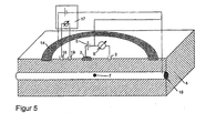
- FIG. 5 shows a schematic representation of another modified Embodiment of the invention.
- a Voltage drop in the electrolyte 4 detected by a current flow of the Counter electrode 3 is caused to distant defects of the pipe 16.
- One Controller 17 is coupled to the reference electrodes 18 and 19 and controls one between the formed as a guard ring auxiliary electrode 14 and the pipe 16 applied voltage such that the voltage between the reference electrodes 18 and 19 is set to 0V.
- the electric field effect on limits an area within the guard ring.
- a plurality of individual electrodes may be used as the auxiliary electrode be suitably in the direction of extension of the pipeline be arranged to limit the field effect.
- the corrosion can be used any electrochemical reaction in which a corrosion product is involved.
- the corrosion may also be a Coulometric detection of a reduction of a corrosion product done. So can reduce the amount of corrosion products in the presence of a completely oxidized Surface also by coulometric measurement of the reduction of Fe (III) to Fe (II) be determined.
- the choice of reaction or the given electrochemical Controlled variables become cathodic depending on the material protected plant, as well as the surrounding electrolyte.
Landscapes
- Chemical & Material Sciences (AREA)
- Life Sciences & Earth Sciences (AREA)
- General Health & Medical Sciences (AREA)
- General Physics & Mathematics (AREA)
- Environmental Sciences (AREA)
- Physics & Mathematics (AREA)
- Health & Medical Sciences (AREA)
- Ecology (AREA)
- Analytical Chemistry (AREA)
- Biochemistry (AREA)
- Biodiversity & Conservation Biology (AREA)
- Environmental & Geological Engineering (AREA)
- Immunology (AREA)
- Pathology (AREA)
- Engineering & Computer Science (AREA)
- Materials Engineering (AREA)
- Mechanical Engineering (AREA)
- Metallurgy (AREA)
- Organic Chemistry (AREA)
- Testing Resistance To Weather, Investigating Materials By Mechanical Methods (AREA)
- Investigating Or Analyzing Materials By The Use Of Electric Means (AREA)
Applications Claiming Priority (2)
| Application Number | Priority Date | Filing Date | Title |
|---|---|---|---|
| DE200410025343 DE102004025343A1 (de) | 2004-05-19 | 2004-05-19 | Verfahren und Anordnung zum Erfassen von Wechselstromkorrosion an kathodisch geschützten Anlagen |
| DE102004025343 | 2004-05-19 |
Publications (2)
| Publication Number | Publication Date |
|---|---|
| EP1598446A2 true EP1598446A2 (fr) | 2005-11-23 |
| EP1598446A3 EP1598446A3 (fr) | 2006-07-19 |
Family
ID=34935340
Family Applications (1)
| Application Number | Title | Priority Date | Filing Date |
|---|---|---|---|
| EP05008456A Withdrawn EP1598446A3 (fr) | 2004-05-19 | 2005-04-19 | Procédé et dispositif de détection de corrosion par courant alternatif dans des installations ayant une protection cathodique |
Country Status (2)
| Country | Link |
|---|---|
| EP (1) | EP1598446A3 (fr) |
| DE (1) | DE102004025343A1 (fr) |
Cited By (2)
| Publication number | Priority date | Publication date | Assignee | Title |
|---|---|---|---|---|
| FR2983582A1 (fr) * | 2011-12-05 | 2013-06-07 | Gdf Suez | Surveillance d'une canalisation enterree soumise a protection cathodique |
| US11598714B1 (en) * | 2021-06-17 | 2023-03-07 | Matergenics, Inc. | Alternating current interference corrosion detector |
Families Citing this family (2)
| Publication number | Priority date | Publication date | Assignee | Title |
|---|---|---|---|---|
| DE102015105410A1 (de) | 2015-04-09 | 2016-10-13 | Endress + Hauser Conducta Gesellschaft für Mess- und Regeltechnik mbH + Co. KG | Vorrichtung zur Überwachung der Auflösung eines Probenmaterials |
| CN108982343B (zh) * | 2018-08-07 | 2021-07-06 | 中国石油大学(华东) | 一种杂散电流腐蚀形貌原位观察实验装置 |
Family Cites Families (3)
| Publication number | Priority date | Publication date | Assignee | Title |
|---|---|---|---|---|
| US5469048A (en) * | 1994-06-13 | 1995-11-21 | Meridian Oil Inc. | Cathodic protection measurement apparatus |
| EP1152235A1 (fr) * | 2000-05-04 | 2001-11-07 | Ionpro N.V. | Système pour mesurer continuellement dans le temps et dans l'espace l'état de corrosion de structures métalliques enterrées |
| DE10021994A1 (de) * | 2000-05-05 | 2001-11-08 | Ruhrgas Ag | Verfahren zur Bestimmung des Rohr/Bodenpotentials an kathodisch geschützten Rohrleitungen |
-
2004
- 2004-05-19 DE DE200410025343 patent/DE102004025343A1/de not_active Withdrawn
-
2005
- 2005-04-19 EP EP05008456A patent/EP1598446A3/fr not_active Withdrawn
Cited By (3)
| Publication number | Priority date | Publication date | Assignee | Title |
|---|---|---|---|---|
| FR2983582A1 (fr) * | 2011-12-05 | 2013-06-07 | Gdf Suez | Surveillance d'une canalisation enterree soumise a protection cathodique |
| EP2602609A1 (fr) * | 2011-12-05 | 2013-06-12 | Gdf Suez | Surveillance d'une canalisation enterree soumise a protection cathodique |
| US11598714B1 (en) * | 2021-06-17 | 2023-03-07 | Matergenics, Inc. | Alternating current interference corrosion detector |
Also Published As
| Publication number | Publication date |
|---|---|
| DE102004025343A1 (de) | 2005-12-08 |
| EP1598446A3 (fr) | 2006-07-19 |
Similar Documents
| Publication | Publication Date | Title |
|---|---|---|
| DE2612498C2 (de) | Verfahren und Vorrichtung zum Messen des Polarisationspotentials von in einem Elektrolyten in einem Stromfeld angeordneten Metallgegenstand | |
| DE60220035T2 (de) | Sensor-array-vorrichtung sowie ein verfahren zur überwachung von elektrochemischer korrosion | |
| DE3010750C2 (fr) | ||
| DE2916934C2 (de) | Verfahren und Vorrichtung zur Aufrechterhaltung eines kathodischen Korrosionsschutzes | |
| EP0581081A1 (fr) | Méthode pour la détermination des péracides | |
| DE102019120446A1 (de) | Verfahren zur Korrektur von zwei Messwerten von jeweils verschiedener Analysenmessgeräte sowie Messstelle zum Ausführen des Verfahrens | |
| DE69315948T2 (de) | Methode und Gerät zur Messung von lokalisierten Korrosionstaten unter Depots oder Metallkorrisionsraten unter losen Depots in Kühlwassersystemen | |
| DE3135639A1 (de) | "verfahren zum messen des potentials in bezug auf den boden einer kathodisch geschuetzten metallkonstruktion" | |
| DE102016222538B3 (de) | Verfahren und Anordnung zur Beurteilung der Korrosion und Passivierung der Bewehrung unter Berücksichtigung der Feuchte in bewehrtem Beton | |
| EP2605007B1 (fr) | Procédé de nettoyage de surfaces d'électrodes | |
| EP1598446A2 (fr) | Procédé et dispositif de détection de corrosion par courant alternatif dans des installations ayant une protection cathodique | |
| WO2016146624A1 (fr) | Dispositif et procédé pour caractériser un agent de refroidissement | |
| EP1164186A2 (fr) | Méthode pour l'examen de compartiments biologiques entourés par des membranes | |
| DE69318933T2 (de) | Verfahren zur Feststellung von wesentlichen Bestandteilen in andere mitniedersetzende Bestandteile enthaltenden Plattierungsbädern | |
| DE2241648A1 (de) | Verfahren zur messung des schutzpotentials kathodisch geschuetzter objekte | |
| DE3022634A1 (de) | Verfahren und vorrichtung zur raschen bestimmung der korrosionsbestaendigkeit einer elektrophoretischen beschichtung | |
| DE1498996A1 (de) | Vorrichtung und Verfahren zur insitu-Messung der schaedigenden Einwirkung des Umgebungsmilieus auf einen metallischen Werkstoff | |
| WO2016074836A1 (fr) | Tuyau de transport | |
| EP0551544B1 (fr) | Méthode de contrÔle de l'état de corrosion des poteaux et pylÔnes enfoncés dans des fondations de ciment | |
| DE102017104971A1 (de) | Verfahren zur Ermittlung einer Ozonkonzentration in einer wässrigen Lösung | |
| DE69127685T2 (de) | Verfahren und Vorrichtung für die Überprüfung des elektrischen Isolierungszustands einer elektrisch leitenden Konstruktion | |
| CH708614A2 (de) | Verfahren zur Ortung von Stahloberflächen in Kontakt mit einem Elektrolyten und zur Ermittlung von deren Korrosionszustand. | |
| DE2707265C2 (de) | Meßvorrichtung zur Ermittlung des Metall-/Boden-Potentials kathodisch geschützter Metallkörper | |
| EP2390383A2 (fr) | Procédé de détection de dommages de l'enveloppe d'objets posés dans la terre et/ou dans des eaux et dotés d'une protection anti-corrosion cathodique | |
| CH708249A2 (de) | Verfahren zur Ermittlung von passivierenden Eigenschaften von Metalloberflächen in Elektrolyten und zur Lokalisierung von Korrosion. |
Legal Events
| Date | Code | Title | Description |
|---|---|---|---|
| PUAI | Public reference made under article 153(3) epc to a published international application that has entered the european phase |
Free format text: ORIGINAL CODE: 0009012 |
|
| AK | Designated contracting states |
Kind code of ref document: A2 Designated state(s): AT BE BG CH CY CZ DE DK EE ES FI FR GB GR HU IE IS IT LI LT LU MC NL PL PT RO SE SI SK TR |
|
| AX | Request for extension of the european patent |
Extension state: AL BA HR LV MK YU |
|
| PUAL | Search report despatched |
Free format text: ORIGINAL CODE: 0009013 |
|
| AK | Designated contracting states |
Kind code of ref document: A3 Designated state(s): AT BE BG CH CY CZ DE DK EE ES FI FR GB GR HU IE IS IT LI LT LU MC NL PL PT RO SE SI SK TR |
|
| AX | Request for extension of the european patent |
Extension state: AL BA HR LV MK YU |
|
| 17P | Request for examination filed |
Effective date: 20061127 |
|
| AKX | Designation fees paid |
Designated state(s): AT BE BG CH CY CZ DE DK EE ES FI FR GB GR HU IE IS IT LI LT LU MC NL PL PT RO SE SI SK TR |
|
| 17Q | First examination report despatched |
Effective date: 20080225 |
|
| STAA | Information on the status of an ep patent application or granted ep patent |
Free format text: STATUS: THE APPLICATION IS DEEMED TO BE WITHDRAWN |
|
| 18D | Application deemed to be withdrawn |
Effective date: 20111101 |