EP1598510A2 - Ein verstellbares Türscharnier - Google Patents
Ein verstellbares Türscharnier Download PDFInfo
- Publication number
- EP1598510A2 EP1598510A2 EP05425311A EP05425311A EP1598510A2 EP 1598510 A2 EP1598510 A2 EP 1598510A2 EP 05425311 A EP05425311 A EP 05425311A EP 05425311 A EP05425311 A EP 05425311A EP 1598510 A2 EP1598510 A2 EP 1598510A2
- Authority
- EP
- European Patent Office
- Prior art keywords
- pin
- bush
- hinge
- protrusion
- hole
- Prior art date
- Legal status (The legal status is an assumption and is not a legal conclusion. Google has not performed a legal analysis and makes no representation as to the accuracy of the status listed.)
- Granted
Links
Images



Classifications
-
- E—FIXED CONSTRUCTIONS
- E05—LOCKS; KEYS; WINDOW OR DOOR FITTINGS; SAFES
- E05D—HINGES OR SUSPENSION DEVICES FOR DOORS, WINDOWS OR WINGS
- E05D7/00—Hinges or pivots of special construction
- E05D7/0009—Adjustable hinges
- E05D7/0018—Adjustable hinges at the hinge axis
- E05D7/0045—Adjustable hinges at the hinge axis in a radial direction
-
- E—FIXED CONSTRUCTIONS
- E05—LOCKS; KEYS; WINDOW OR DOOR FITTINGS; SAFES
- E05D—HINGES OR SUSPENSION DEVICES FOR DOORS, WINDOWS OR WINGS
- E05D11/00—Additional features or accessories of hinges
- E05D11/0054—Covers, e.g. for protection
-
- E—FIXED CONSTRUCTIONS
- E05—LOCKS; KEYS; WINDOW OR DOOR FITTINGS; SAFES
- E05D—HINGES OR SUSPENSION DEVICES FOR DOORS, WINDOWS OR WINGS
- E05D7/00—Hinges or pivots of special construction
- E05D7/0009—Adjustable hinges
- E05D7/0018—Adjustable hinges at the hinge axis
- E05D7/0045—Adjustable hinges at the hinge axis in a radial direction
- E05D2007/0081—Adjustable hinges at the hinge axis in a radial direction with swinging or rolling sleeves
-
- E—FIXED CONSTRUCTIONS
- E05—LOCKS; KEYS; WINDOW OR DOOR FITTINGS; SAFES
- E05Y—INDEXING SCHEME ASSOCIATED WITH SUBCLASSES E05D AND E05F, RELATING TO CONSTRUCTION ELEMENTS, ELECTRIC CONTROL, POWER SUPPLY, POWER SIGNAL OR TRANSMISSION, USER INTERFACES, MOUNTING OR COUPLING, DETAILS, ACCESSORIES, AUXILIARY OPERATIONS NOT OTHERWISE PROVIDED FOR, APPLICATION THEREOF
- E05Y2900/00—Application of doors, windows, wings or fittings thereof
- E05Y2900/10—Application of doors, windows, wings or fittings thereof for buildings or parts thereof
- E05Y2900/13—Type of wing
- E05Y2900/132—Doors
Definitions
- the present invention relates to an adjustable door hinge, in particular for heavy metal door units, that is to say, reinforced door units that are heavier than standard interior door units.
- hinges used for door units of this type must also satisfy special security requirements and, in this aspect too, differ from those usually used on standard door units (for interiors).
- hinges must have a larger and stronger structure, not only because they have to support the heavy weight of the door but also because the screws used to fix the hinges have to be covered by special tamper-proof plates.
- the hinges normally consist of two hinge bodies, usually of aluminium or an aluminium alloy, one attachable to the mobile frame of the door unit and one attachable to the fixed frame, and a steel hinge pin that can be inserted into respective through holes in the two hinge bodies with interposed centring bushes (usually made of self-lubricating plastic).
- a collar made as a single piece with the hinge pin itself, and larger in diameter than the through holes in the hinge bodies so as to prevent the pin from coming out of the holes in the hinge bodies (see also patent IT-1.221.237 to the same Applicant).
- the hinge bodies have flaps by which the hinge is secured to the door unit and which are crossed, perpendicularly to the hinge pin, by robust screws whose heads are accommodated in respective recesses made in the hinge flaps themselves.
- the hinge flaps present guides defining seats for respective caps that slide in a direction parallel with the hinge pin.
- the caps fully cover the screw heads and form a surface that smoothly connects both with the cylindrical portion of the hinge in which the hole that accommodates the respective bush is made, and with the free end of the hinge flap extending from the cylindrical portion and including the cap guides.
- the above mentioned bushes usually consist of a cylindrical element closed at one end and a collar located at the open end. They also have an axial hole, offset relative to the longitudinal axis of the cylindrical element, and a series of protrusions or teeth, usually located on the outside of the bush and designed to fit in respective grooves made inside the holes in the hinge bodies so as to secure the bush-pin assembly in a stable position relative to the cylindrical element.
- the shape of the bushes enables the axis of the hinge pin to be moved relative to the axis of the hole that accommodates the bush-pin assembly, thereby adjusting the position of the mobile frame of the door unit relative to the fixed frame.
- an adjustable door hinge in which the bush has an outer radial protrusion that engages in a matching notch made in the inside surface of the hole in the hinge body so as to form a pivot point that allows a pendular movement of the bush in both directions as one with the pin it accommodates, this pendular movement being produced by an adjustment device actuated from the outside.
- This adjustment device comprises a screw positioned transversally with respect to the pin and bush and designed to engage with the pin or the bush or both.
- the hinge is supplied ready-assembled, for example for right-hand opening doors, and when a left-hand opening door has to be installed, the installer must completely dismantle all the components of the hinge (including bushes, pin, adjustment screw system, and so on), turn them by 180° and then reassemble them in the new position.
- the present invention has for an aim to overcome the above mentioned disadvantages by providing a hinge for door units that has a simple structure and that is practical and easy to install.
- Another aim of the invention is to provide a hinge that is extremely easy to adjust.
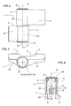
- the numeral 1 denotes a hinge according to the present invention, used in particular for "heavy" doors, such as exterior doors, main front doors, gates, etc.
- the hinge labelled 1 in its entirety, comprises a first body 2 and a second body 3 attachable, respectively, to a mobile frame of a door unit and to a fixed frame of a door unit (not illustrated since they are of well known type and do not fall within the scope of this invention) by means of respective flaps 4 and 5 that accommodate respective screw fixing means (also not illustrated).
- the hinge 1 comprises a pin 6 for joining the two hinge bodies 2 and 3.
- the pin 6 has a central axis A6 and can be inserted, with interposed first and second bushes cylindrical centring bushes 7 and 8, respectively upper and lower, into respective axial through holes 9 and 10 made in the first and second hinge bodies 2 and 3 and extending along respective longitudinal axes A9, A10.
- the bushes 7, 8 have respective central axes A7, A8 which, when the bushes 7, 8 themselves are fitted inside the holes 9, 10 in the hinge bodies 2, 3, are parallel with the respective axes A9, A10 of the holes 9, 10 and coincide with the axis A6 of the pin 6.
- the bush 8 is not illustrated or described in detail since it is of known type and does not strictly form part of the present invention.
- the upper bush 7 comprises a first and a second radial protrusion 11 and 12 extending longitudinally parallel with the central axis A7.
- the first and second protrusions 11, 12 of the upper bush 7 are located diametrically opposite each other and are shaped symmetrically about a plane passing through the above mentioned axis A7 of the bush 7 itself represented by a dashed line P in Figure 5.
- the hole 9 made in the upper hinge 1 body 2 comprises an inside face 9a in which there is a first recess 13 extending longitudinally for the entire axial extension of the hole 9 and in a direction parallel with the axis A9 of the hole 9 itself.
- the first recess 13 has an inside surface that is substantially defined by a cylindrical sector.
- the inside face 9a of the hole 9 has a second recess 14 also extending for the entire axial extension of the hole 9 and in a direction parallel with the first recess 13.
- the second recess 14 has a central section positioned diametrically opposite the first recess 13.
- the coupling between the bush 7 and the pin 6 is accomplished by a grooved profile 15 which constitutes hinge 1 engagement and locking means 16 designed to prevent the pin 6 and the bush 7 from rotating relative to each other about the axis A6.
- the bush 7 has a blind hole 17 in which an upper portion 6a of the pin 6 is inserted.
- the grooved profile 15 is made between the blind hole 17 and the upper portion 6a of the pin 6.
- the hinge 1 comprises, between the first upper bush 7 and the related hole 9, an element 18 for adjusting the position of the hinge pin 6.
- the adjustment element 18 is threaded so that it can be screwed into the pin 6 or the bush 7 or both.
- the adjustment element 18 thus operates between the hole 10 and the assembly formed by the bush 7 and the pin 6, in such a way as to enable this assembly to move within the hole 9 while keeping the pin axis A6 parallel with the axis A9 of the hole 9.
- the adjustment element 18 is screwed into the bush 7, which has a matching threaded hole made in it.
- the adjustment element 18 may be screwed into a threaded hole made in the pin 6 and leading to the outside through appropriate openings made in the bush 7.
- the openings in the bush are originally smaller in diameter than the adjustment element 18 so that when the hinge is installed they are deformed in such a way as to produce a self-locking action between the adjustment element 18 and the upper bush 7.
- the threaded adjustment element 18 is screwed into the bush 7 before the pin 6-bush 7 assembly is inserted into the hole 9. In this way, the element 18 goes all the way inside the hole 9 and its end 18a is in contact with the curved inside face 9a of the hole 9, while its second end 18b partly faces a slot 19.
- the slot 19 is arc-shaped, passes through the side wall of the hinge body 2 and is smaller in size than the second end 18b of the adjustment element 18. Through the slot 19, therefore, the adjustment element 18 can be moved in both directions from outside the hinge body 2, using a customary tool that is not illustrated.
- the pin 6-bush 7 assembly is made to perform a pendular movement defined by the rotation of the assembly itself about an instantaneous axis of rotation R defined by the engagement of the protrusion 11, 12 with the first recess 13 (see arrows F, Figure 5).
- the engagement of the protrusion 11, 12 in the first recess 13 instantaneously defines an axis of rotation R parallel with the central axis A7 of the bush and the pin 6-bush 7 assembly is made to rotate instantaneously about the axis A7 by the rotation of the adjustment element 18.
- the first recess 13 has an inside surface 13a defined and delimited by a cylindrical sector.
- first and second protrusions 11, 12 each have two rounded portions 20, shown more clearly in the drawings only on the protrusion 12, these rounded portions 20 being designed to engage with the cylindrical sector of the inside surface 13a of the first recess 13, thereby forming a substantially cylindrical joint between the hinge body 2 and the bush 7 attached to the pin 6.
- the plates 21 and 23 are clearly illustrated in Figures 2 and 3.
- Caps 25 are provided to cover the free ends of the holes 9 and 10 in the hinge bodies 2 and 3.
- Figure 9 illustrates a prior art hinge comprising a bush 7 having only one protrusion 11.
- the parts of the prior art hinge of Figure 9 that are the same as those of the hinge according to the present invention are denoted by the same reference numbers.
- the prior art hinge once assembled for example for a right-hand opening door, is not immediately reversible to another configuration for use on a left-hand opening door.
- the presence of the second protrusion 12 eliminates the need for many of the operations described above to adapt the hinge 1 to a right- or left-hand opening door.
- the new hinge configuration makes it possible to fit the bush 7 and the pin 6 together to form a single assembly whether the adjustment element 18 is in place or not.
- the pin 6 may have a portion 6a, housed in the bush 7, with threading 6f that enables it to be screwed into the threaded seat 7f made in the bush 7 itself.
- the portion 6a of the pin 6 may be stably housed in the seat 7a in the bush 7 by means of an interference fit.
- the hinge according to the invention therefore achieves the preset aims thanks to a very simple structural modification, that is to say, the twin protrusion, which does not affect the basic structure of the hinge but which allows the hinge to be quickly and precisely adapted for right- or left-hand opening doors by means of a "setting" that is much faster than in previous solutions.
Landscapes
- Engineering & Computer Science (AREA)
- Mechanical Engineering (AREA)
- Hinges (AREA)
Applications Claiming Priority (2)
| Application Number | Priority Date | Filing Date | Title |
|---|---|---|---|
| ITBO20040316 | 2004-05-18 | ||
| IT000316A ITBO20040316A1 (it) | 2004-05-18 | 2004-05-18 | Cerniera regolabile per infissi. |
Publications (3)
| Publication Number | Publication Date |
|---|---|
| EP1598510A2 true EP1598510A2 (de) | 2005-11-23 |
| EP1598510A3 EP1598510A3 (de) | 2007-05-02 |
| EP1598510B1 EP1598510B1 (de) | 2009-02-18 |
Family
ID=34943192
Family Applications (1)
| Application Number | Title | Priority Date | Filing Date |
|---|---|---|---|
| EP05425311A Expired - Lifetime EP1598510B1 (de) | 2004-05-18 | 2005-05-11 | Ein verstellbares Türscharnier |
Country Status (5)
| Country | Link |
|---|---|
| EP (1) | EP1598510B1 (de) |
| AT (1) | ATE423259T1 (de) |
| DE (1) | DE602005012753D1 (de) |
| ES (1) | ES2321957T3 (de) |
| IT (1) | ITBO20040316A1 (de) |
Cited By (7)
| Publication number | Priority date | Publication date | Assignee | Title |
|---|---|---|---|---|
| DE102009004847A1 (de) * | 2008-10-16 | 2010-04-29 | Hörmann KG Verkaufsgesellschaft | Türband, insbesondere für Falttore |
| EP2194218A1 (de) * | 2008-12-05 | 2010-06-09 | SAVIO S.p.A. | Scharnier für Türen, Fenster oder ähnliches |
| EP2182151A3 (de) * | 2008-10-30 | 2010-08-18 | Window Fabrication & Fixing Supplies Limited | Verstellscharnier |
| DE102015226546A1 (de) * | 2015-12-22 | 2017-06-22 | Rolls-Royce Deutschland Ltd & Co Kg | Triebwerksverkleidung |
| DE202017103105U1 (de) * | 2017-05-23 | 2018-08-24 | Dr. Hahn Gmbh & Co. Kg | Band zur um eine Scharnierachse scharniergelenkigen Befestigung eines Flügels an einem Rahmen |
| US11767694B2 (en) * | 2017-11-24 | 2023-09-26 | Sugatsune Kogyo Co., Ltd. | Hinge |
| EP4375462A1 (de) * | 2022-11-28 | 2024-05-29 | Wilh. Schlechtendahl & Söhne GmbH & Co. KG | Beschlagsteil |
Family Cites Families (1)
| Publication number | Priority date | Publication date | Assignee | Title |
|---|---|---|---|---|
| IT1304490B1 (it) * | 1998-10-05 | 2001-03-19 | Giesse Spa | Cerniera regolabile per infissi . |
-
2004
- 2004-05-18 IT IT000316A patent/ITBO20040316A1/it unknown
-
2005
- 2005-05-11 EP EP05425311A patent/EP1598510B1/de not_active Expired - Lifetime
- 2005-05-11 AT AT05425311T patent/ATE423259T1/de not_active IP Right Cessation
- 2005-05-11 DE DE602005012753T patent/DE602005012753D1/de not_active Expired - Lifetime
- 2005-05-11 ES ES05425311T patent/ES2321957T3/es not_active Expired - Lifetime
Cited By (14)
| Publication number | Priority date | Publication date | Assignee | Title |
|---|---|---|---|---|
| DE102009004847A1 (de) * | 2008-10-16 | 2010-04-29 | Hörmann KG Verkaufsgesellschaft | Türband, insbesondere für Falttore |
| RU2519999C2 (ru) * | 2008-10-30 | 2014-06-20 | Виндоу Фабрикейшн Энд Фиксинг Саплайз Лимитед | Регулируемая петля |
| EP2182151A3 (de) * | 2008-10-30 | 2010-08-18 | Window Fabrication & Fixing Supplies Limited | Verstellscharnier |
| CN101748946A (zh) * | 2008-12-05 | 2010-06-23 | 萨维奥股份有限公司 | 用于门、窗或类似装置的铰链 |
| US8281458B2 (en) | 2008-12-05 | 2012-10-09 | Savio S.P.A. | Hinge for doors, windows, or the like |
| CN101748946B (zh) * | 2008-12-05 | 2014-03-12 | 萨维奥股份有限公司 | 用于门或窗的铰链 |
| EP2194218A1 (de) * | 2008-12-05 | 2010-06-09 | SAVIO S.p.A. | Scharnier für Türen, Fenster oder ähnliches |
| DE102015226546A1 (de) * | 2015-12-22 | 2017-06-22 | Rolls-Royce Deutschland Ltd & Co Kg | Triebwerksverkleidung |
| US10081435B2 (en) | 2015-12-22 | 2018-09-25 | Rolls-Royce Deutschland Ltd & Co Kg | Engine cowling |
| DE202017103105U1 (de) * | 2017-05-23 | 2018-08-24 | Dr. Hahn Gmbh & Co. Kg | Band zur um eine Scharnierachse scharniergelenkigen Befestigung eines Flügels an einem Rahmen |
| CN110651095A (zh) * | 2017-05-23 | 2020-01-03 | 哈恩两合公司 | 用于将翼扇围绕铰链轴线铰链铰接式紧固在框架上的铰链 |
| CN110651095B (zh) * | 2017-05-23 | 2021-08-31 | 哈恩两合公司 | 用于将翼扇围绕铰链轴线铰链铰接式紧固在框架上的铰链 |
| US11767694B2 (en) * | 2017-11-24 | 2023-09-26 | Sugatsune Kogyo Co., Ltd. | Hinge |
| EP4375462A1 (de) * | 2022-11-28 | 2024-05-29 | Wilh. Schlechtendahl & Söhne GmbH & Co. KG | Beschlagsteil |
Also Published As
| Publication number | Publication date |
|---|---|
| ATE423259T1 (de) | 2009-03-15 |
| EP1598510B1 (de) | 2009-02-18 |
| ES2321957T3 (es) | 2009-06-15 |
| DE602005012753D1 (de) | 2009-04-02 |
| EP1598510A3 (de) | 2007-05-02 |
| ITBO20040316A1 (it) | 2004-08-18 |
Similar Documents
| Publication | Publication Date | Title |
|---|---|---|
| EP0992647B1 (de) | Verstellbares Scharnier für Türrahmen | |
| CA2909421C (en) | Hinge | |
| EP2710212B1 (de) | Kolbenvorrichtung zur kontrollierten drehbaren bewegung von türen, klappen oder dergleichen | |
| US7779510B2 (en) | Multi-axis door hinge | |
| EP1061221A1 (de) | Scharnier für einen zu öffnenden Tür- oder Fensterrahmen | |
| US6478345B1 (en) | Multi point bolting mechanism | |
| EP2194218B1 (de) | Scharnier für Türen, Fenster oder ähnliches | |
| EP2182151B1 (de) | Verstellscharnier | |
| US8893352B2 (en) | Hinge with adjustment elements and adjustment crown for adjustment elements | |
| EP3480398B1 (de) | Verbindungssystem für die lösbare befestigung eines beschlagteiles für fenster oder türen | |
| EP1598510B1 (de) | Ein verstellbares Türscharnier | |
| GB2276204A (en) | Adjustable hinge | |
| EP1455042B1 (de) | Verstellbares Scharnier für Fenster oder Türen | |
| EP2872717B1 (de) | Scharnier für die rotierende bewegung einer tür, insbesondere einer verstärkte tür | |
| US20040205932A1 (en) | Hinge for doors and similar construction components | |
| US20070240283A1 (en) | Hinged for doors or windows | |
| GB2230557A (en) | A hinge | |
| EP1512817B1 (de) | Band für Türen, Fenster oder dergleichen | |
| BE1032270B1 (nl) | Regelsysteem van het beslag van een kipbaar en/of draaibaar raam | |
| EP1640538B1 (de) | Charnière de porte réglable | |
| US20240352777A1 (en) | Hinge assembly | |
| EP2004940B1 (de) | Scharnier für fenster, türen und dergleichen | |
| GB2579796A (en) | Hinges | |
| EP1036905A2 (de) | Links- oder rechtsseitiges Verschlussscharnier | |
| HK1258901A1 (zh) | 可三维调节的门铰链 |
Legal Events
| Date | Code | Title | Description |
|---|---|---|---|
| PUAI | Public reference made under article 153(3) epc to a published international application that has entered the european phase |
Free format text: ORIGINAL CODE: 0009012 |
|
| AK | Designated contracting states |
Kind code of ref document: A2 Designated state(s): AT BE BG CH CY CZ DE DK EE ES FI FR GB GR HU IE IS IT LI LT LU MC NL PL PT RO SE SI SK TR |
|
| AX | Request for extension of the european patent |
Extension state: AL BA HR LV MK YU |
|
| PUAL | Search report despatched |
Free format text: ORIGINAL CODE: 0009013 |
|
| AK | Designated contracting states |
Kind code of ref document: A3 Designated state(s): AT BE BG CH CY CZ DE DK EE ES FI FR GB GR HU IE IS IT LI LT LU MC NL PL PT RO SE SI SK TR |
|
| AX | Request for extension of the european patent |
Extension state: AL BA HR LV MK YU |
|
| 17P | Request for examination filed |
Effective date: 20070620 |
|
| AKX | Designation fees paid |
Designated state(s): AT BE BG CH CY CZ DE DK EE ES FI FR GB GR HU IE IS IT LI LT LU MC NL PL PT RO SE SI SK TR |
|
| GRAP | Despatch of communication of intention to grant a patent |
Free format text: ORIGINAL CODE: EPIDOSNIGR1 |
|
| GRAS | Grant fee paid |
Free format text: ORIGINAL CODE: EPIDOSNIGR3 |
|
| GRAA | (expected) grant |
Free format text: ORIGINAL CODE: 0009210 |
|
| AK | Designated contracting states |
Kind code of ref document: B1 Designated state(s): AT BE BG CH CY CZ DE DK EE ES FI FR GB GR HU IE IS IT LI LT LU MC NL PL PT RO SE SI SK TR |
|
| REG | Reference to a national code |
Ref country code: GB Ref legal event code: FG4D |
|
| REG | Reference to a national code |
Ref country code: CH Ref legal event code: EP |
|
| REG | Reference to a national code |
Ref country code: IE Ref legal event code: FG4D |
|
| REF | Corresponds to: |
Ref document number: 602005012753 Country of ref document: DE Date of ref document: 20090402 Kind code of ref document: P |
|
| REG | Reference to a national code |
Ref country code: GR Ref legal event code: EP Ref document number: 20090401224 Country of ref document: GR |
|
| REG | Reference to a national code |
Ref country code: ES Ref legal event code: FG2A Ref document number: 2321957 Country of ref document: ES Kind code of ref document: T3 |
|
| PG25 | Lapsed in a contracting state [announced via postgrant information from national office to epo] |
Ref country code: NL Free format text: LAPSE BECAUSE OF FAILURE TO SUBMIT A TRANSLATION OF THE DESCRIPTION OR TO PAY THE FEE WITHIN THE PRESCRIBED TIME-LIMIT Effective date: 20090218 Ref country code: FI Free format text: LAPSE BECAUSE OF FAILURE TO SUBMIT A TRANSLATION OF THE DESCRIPTION OR TO PAY THE FEE WITHIN THE PRESCRIBED TIME-LIMIT Effective date: 20090218 Ref country code: LT Free format text: LAPSE BECAUSE OF FAILURE TO SUBMIT A TRANSLATION OF THE DESCRIPTION OR TO PAY THE FEE WITHIN THE PRESCRIBED TIME-LIMIT Effective date: 20090218 Ref country code: SI Free format text: LAPSE BECAUSE OF FAILURE TO SUBMIT A TRANSLATION OF THE DESCRIPTION OR TO PAY THE FEE WITHIN THE PRESCRIBED TIME-LIMIT Effective date: 20090218 |
|
| NLV1 | Nl: lapsed or annulled due to failure to fulfill the requirements of art. 29p and 29m of the patents act | ||
| PG25 | Lapsed in a contracting state [announced via postgrant information from national office to epo] |
Ref country code: PL Free format text: LAPSE BECAUSE OF FAILURE TO SUBMIT A TRANSLATION OF THE DESCRIPTION OR TO PAY THE FEE WITHIN THE PRESCRIBED TIME-LIMIT Effective date: 20090218 Ref country code: IS Free format text: LAPSE BECAUSE OF FAILURE TO SUBMIT A TRANSLATION OF THE DESCRIPTION OR TO PAY THE FEE WITHIN THE PRESCRIBED TIME-LIMIT Effective date: 20090618 Ref country code: SE Free format text: LAPSE BECAUSE OF FAILURE TO SUBMIT A TRANSLATION OF THE DESCRIPTION OR TO PAY THE FEE WITHIN THE PRESCRIBED TIME-LIMIT Effective date: 20090518 Ref country code: AT Free format text: LAPSE BECAUSE OF FAILURE TO SUBMIT A TRANSLATION OF THE DESCRIPTION OR TO PAY THE FEE WITHIN THE PRESCRIBED TIME-LIMIT Effective date: 20090218 |
|
| PG25 | Lapsed in a contracting state [announced via postgrant information from national office to epo] |
Ref country code: BE Free format text: LAPSE BECAUSE OF FAILURE TO SUBMIT A TRANSLATION OF THE DESCRIPTION OR TO PAY THE FEE WITHIN THE PRESCRIBED TIME-LIMIT Effective date: 20090218 |
|
| PG25 | Lapsed in a contracting state [announced via postgrant information from national office to epo] |
Ref country code: DK Free format text: LAPSE BECAUSE OF FAILURE TO SUBMIT A TRANSLATION OF THE DESCRIPTION OR TO PAY THE FEE WITHIN THE PRESCRIBED TIME-LIMIT Effective date: 20090218 Ref country code: PT Free format text: LAPSE BECAUSE OF FAILURE TO SUBMIT A TRANSLATION OF THE DESCRIPTION OR TO PAY THE FEE WITHIN THE PRESCRIBED TIME-LIMIT Effective date: 20090727 Ref country code: CZ Free format text: LAPSE BECAUSE OF FAILURE TO SUBMIT A TRANSLATION OF THE DESCRIPTION OR TO PAY THE FEE WITHIN THE PRESCRIBED TIME-LIMIT Effective date: 20090218 Ref country code: EE Free format text: LAPSE BECAUSE OF FAILURE TO SUBMIT A TRANSLATION OF THE DESCRIPTION OR TO PAY THE FEE WITHIN THE PRESCRIBED TIME-LIMIT Effective date: 20090218 |
|
| PG25 | Lapsed in a contracting state [announced via postgrant information from national office to epo] |
Ref country code: RO Free format text: LAPSE BECAUSE OF FAILURE TO SUBMIT A TRANSLATION OF THE DESCRIPTION OR TO PAY THE FEE WITHIN THE PRESCRIBED TIME-LIMIT Effective date: 20090218 Ref country code: SK Free format text: LAPSE BECAUSE OF FAILURE TO SUBMIT A TRANSLATION OF THE DESCRIPTION OR TO PAY THE FEE WITHIN THE PRESCRIBED TIME-LIMIT Effective date: 20090218 |
|
| PLBE | No opposition filed within time limit |
Free format text: ORIGINAL CODE: 0009261 |
|
| STAA | Information on the status of an ep patent application or granted ep patent |
Free format text: STATUS: NO OPPOSITION FILED WITHIN TIME LIMIT |
|
| PG25 | Lapsed in a contracting state [announced via postgrant information from national office to epo] |
Ref country code: MC Free format text: LAPSE BECAUSE OF NON-PAYMENT OF DUE FEES Effective date: 20090531 |
|
| REG | Reference to a national code |
Ref country code: CH Ref legal event code: PL |
|
| 26N | No opposition filed |
Effective date: 20091119 |
|
| GBPC | Gb: european patent ceased through non-payment of renewal fee |
Effective date: 20090518 |
|
| PG25 | Lapsed in a contracting state [announced via postgrant information from national office to epo] |
Ref country code: BG Free format text: LAPSE BECAUSE OF FAILURE TO SUBMIT A TRANSLATION OF THE DESCRIPTION OR TO PAY THE FEE WITHIN THE PRESCRIBED TIME-LIMIT Effective date: 20090518 Ref country code: LI Free format text: LAPSE BECAUSE OF NON-PAYMENT OF DUE FEES Effective date: 20090531 Ref country code: CH Free format text: LAPSE BECAUSE OF NON-PAYMENT OF DUE FEES Effective date: 20090531 |
|
| PG25 | Lapsed in a contracting state [announced via postgrant information from national office to epo] |
Ref country code: IE Free format text: LAPSE BECAUSE OF NON-PAYMENT OF DUE FEES Effective date: 20090511 |
|
| PG25 | Lapsed in a contracting state [announced via postgrant information from national office to epo] |
Ref country code: GB Free format text: LAPSE BECAUSE OF NON-PAYMENT OF DUE FEES Effective date: 20090518 |
|
| PG25 | Lapsed in a contracting state [announced via postgrant information from national office to epo] |
Ref country code: LU Free format text: LAPSE BECAUSE OF NON-PAYMENT OF DUE FEES Effective date: 20090511 |
|
| PG25 | Lapsed in a contracting state [announced via postgrant information from national office to epo] |
Ref country code: HU Free format text: LAPSE BECAUSE OF FAILURE TO SUBMIT A TRANSLATION OF THE DESCRIPTION OR TO PAY THE FEE WITHIN THE PRESCRIBED TIME-LIMIT Effective date: 20090819 |
|
| PGFP | Annual fee paid to national office [announced via postgrant information from national office to epo] |
Ref country code: FR Payment date: 20110615 Year of fee payment: 7 Ref country code: GR Payment date: 20110527 Year of fee payment: 7 |
|
| PG25 | Lapsed in a contracting state [announced via postgrant information from national office to epo] |
Ref country code: TR Free format text: LAPSE BECAUSE OF FAILURE TO SUBMIT A TRANSLATION OF THE DESCRIPTION OR TO PAY THE FEE WITHIN THE PRESCRIBED TIME-LIMIT Effective date: 20090218 |
|
| PG25 | Lapsed in a contracting state [announced via postgrant information from national office to epo] |
Ref country code: CY Free format text: LAPSE BECAUSE OF FAILURE TO SUBMIT A TRANSLATION OF THE DESCRIPTION OR TO PAY THE FEE WITHIN THE PRESCRIBED TIME-LIMIT Effective date: 20090218 |
|
| REG | Reference to a national code |
Ref country code: GR Ref legal event code: ML Ref document number: 20090401224 Country of ref document: GR Effective date: 20121204 |
|
| PG25 | Lapsed in a contracting state [announced via postgrant information from national office to epo] |
Ref country code: GR Free format text: LAPSE BECAUSE OF NON-PAYMENT OF DUE FEES Effective date: 20121204 |
|
| REG | Reference to a national code |
Ref country code: FR Ref legal event code: ST Effective date: 20130131 |
|
| PG25 | Lapsed in a contracting state [announced via postgrant information from national office to epo] |
Ref country code: FR Free format text: LAPSE BECAUSE OF NON-PAYMENT OF DUE FEES Effective date: 20120531 |
|
| P01 | Opt-out of the competence of the unified patent court (upc) registered |
Effective date: 20230506 |
|
| PGFP | Annual fee paid to national office [announced via postgrant information from national office to epo] |
Ref country code: DE Payment date: 20240529 Year of fee payment: 20 |
|
| PGFP | Annual fee paid to national office [announced via postgrant information from national office to epo] |
Ref country code: ES Payment date: 20240610 Year of fee payment: 20 |
|
| PGFP | Annual fee paid to national office [announced via postgrant information from national office to epo] |
Ref country code: IT Payment date: 20240521 Year of fee payment: 20 |
|
| REG | Reference to a national code |
Ref country code: DE Ref legal event code: R071 Ref document number: 602005012753 Country of ref document: DE |
|
| REG | Reference to a national code |
Ref country code: ES Ref legal event code: FD2A Effective date: 20250526 |
|
| PG25 | Lapsed in a contracting state [announced via postgrant information from national office to epo] |
Ref country code: ES Free format text: LAPSE BECAUSE OF EXPIRATION OF PROTECTION Effective date: 20250512 |