EP1598562A1 - Befestigungsvorrichtung zum Anbringen eines nichtmetallischen Bauteils an einem metallischen Bauteil - Google Patents
Befestigungsvorrichtung zum Anbringen eines nichtmetallischen Bauteils an einem metallischen Bauteil Download PDFInfo
- Publication number
- EP1598562A1 EP1598562A1 EP05251687A EP05251687A EP1598562A1 EP 1598562 A1 EP1598562 A1 EP 1598562A1 EP 05251687 A EP05251687 A EP 05251687A EP 05251687 A EP05251687 A EP 05251687A EP 1598562 A1 EP1598562 A1 EP 1598562A1
- Authority
- EP
- European Patent Office
- Prior art keywords
- metal component
- fastener
- body portion
- spacer
- opening
- Prior art date
- Legal status (The legal status is an assumption and is not a legal conclusion. Google has not performed a legal analysis and makes no representation as to the accuracy of the status listed.)
- Granted
Links
- 229910052751 metal Inorganic materials 0.000 title claims abstract description 69
- 239000002184 metal Substances 0.000 title claims abstract description 67
- 229910052755 nonmetal Inorganic materials 0.000 title claims abstract description 41
- 125000006850 spacer group Chemical group 0.000 claims abstract description 37
- 239000000463 material Substances 0.000 claims abstract description 28
- 230000033001 locomotion Effects 0.000 claims abstract description 7
- 238000000034 method Methods 0.000 claims description 6
- 239000011153 ceramic matrix composite Substances 0.000 description 37
- 239000007789 gas Substances 0.000 description 21
- 230000036316 preload Effects 0.000 description 5
- 238000001514 detection method Methods 0.000 description 4
- 230000035882 stress Effects 0.000 description 3
- 239000000446 fuel Substances 0.000 description 2
- 239000011156 metal matrix composite Substances 0.000 description 2
- 230000008646 thermal stress Effects 0.000 description 2
- 230000015556 catabolic process Effects 0.000 description 1
- 238000006731 degradation reaction Methods 0.000 description 1
- 230000014759 maintenance of location Effects 0.000 description 1
- 150000002739 metals Chemical class 0.000 description 1
- 238000012986 modification Methods 0.000 description 1
- 230000004048 modification Effects 0.000 description 1
- 239000000758 substrate Substances 0.000 description 1
Images



Classifications
-
- F—MECHANICAL ENGINEERING; LIGHTING; HEATING; WEAPONS; BLASTING
- F16—ENGINEERING ELEMENTS AND UNITS; GENERAL MEASURES FOR PRODUCING AND MAINTAINING EFFECTIVE FUNCTIONING OF MACHINES OR INSTALLATIONS; THERMAL INSULATION IN GENERAL
- F16B—DEVICES FOR FASTENING OR SECURING CONSTRUCTIONAL ELEMENTS OR MACHINE PARTS TOGETHER, e.g. NAILS, BOLTS, CIRCLIPS, CLAMPS, CLIPS OR WEDGES; JOINTS OR JOINTING
- F16B5/00—Joining sheets or plates, e.g. panels, to one another or to strips or bars parallel to them
- F16B5/02—Joining sheets or plates, e.g. panels, to one another or to strips or bars parallel to them by means of fastening members using screw-thread
- F16B5/0241—Joining sheets or plates, e.g. panels, to one another or to strips or bars parallel to them by means of fastening members using screw-thread with the possibility for the connection to absorb deformation, e.g. thermal or vibrational
-
- G—PHYSICS
- G01—MEASURING; TESTING
- G01N—INVESTIGATING OR ANALYSING MATERIALS BY DETERMINING THEIR CHEMICAL OR PHYSICAL PROPERTIES
- G01N23/00—Investigating or analysing materials by the use of wave or particle radiation, e.g. X-rays or neutrons, not covered by groups G01N3/00 – G01N17/00, G01N21/00 or G01N22/00
- G01N23/02—Investigating or analysing materials by the use of wave or particle radiation, e.g. X-rays or neutrons, not covered by groups G01N3/00 – G01N17/00, G01N21/00 or G01N22/00 by transmitting the radiation through the material
- G01N23/04—Investigating or analysing materials by the use of wave or particle radiation, e.g. X-rays or neutrons, not covered by groups G01N3/00 – G01N17/00, G01N21/00 or G01N22/00 by transmitting the radiation through the material and forming images of the material
- G01N23/046—Investigating or analysing materials by the use of wave or particle radiation, e.g. X-rays or neutrons, not covered by groups G01N3/00 – G01N17/00, G01N21/00 or G01N22/00 by transmitting the radiation through the material and forming images of the material using tomography, e.g. computed tomography [CT]
-
- B—PERFORMING OPERATIONS; TRANSPORTING
- B62—LAND VEHICLES FOR TRAVELLING OTHERWISE THAN ON RAILS
- B62D—MOTOR VEHICLES; TRAILERS
- B62D29/00—Superstructures, understructures, or sub-units thereof, characterised by the material thereof
- B62D29/04—Superstructures, understructures, or sub-units thereof, characterised by the material thereof predominantly of synthetic material
- B62D29/048—Connections therefor, e.g. joints
-
- F—MECHANICAL ENGINEERING; LIGHTING; HEATING; WEAPONS; BLASTING
- F16—ENGINEERING ELEMENTS AND UNITS; GENERAL MEASURES FOR PRODUCING AND MAINTAINING EFFECTIVE FUNCTIONING OF MACHINES OR INSTALLATIONS; THERMAL INSULATION IN GENERAL
- F16B—DEVICES FOR FASTENING OR SECURING CONSTRUCTIONAL ELEMENTS OR MACHINE PARTS TOGETHER, e.g. NAILS, BOLTS, CIRCLIPS, CLAMPS, CLIPS OR WEDGES; JOINTS OR JOINTING
- F16B35/00—Screw-bolts; Stay-bolts; Screw-threaded studs; Screws; Set screws
- F16B35/04—Screw-bolts; Stay-bolts; Screw-threaded studs; Screws; Set screws with specially-shaped head or shaft in order to fix the bolt on or in an object
- F16B35/06—Specially-shaped heads
-
- F—MECHANICAL ENGINEERING; LIGHTING; HEATING; WEAPONS; BLASTING
- F16—ENGINEERING ELEMENTS AND UNITS; GENERAL MEASURES FOR PRODUCING AND MAINTAINING EFFECTIVE FUNCTIONING OF MACHINES OR INSTALLATIONS; THERMAL INSULATION IN GENERAL
- F16B—DEVICES FOR FASTENING OR SECURING CONSTRUCTIONAL ELEMENTS OR MACHINE PARTS TOGETHER, e.g. NAILS, BOLTS, CIRCLIPS, CLAMPS, CLIPS OR WEDGES; JOINTS OR JOINTING
- F16B37/00—Nuts or like thread-engaging members
- F16B37/04—Devices for fastening nuts to surfaces, e.g. sheets, plates
- F16B37/045—Devices for fastening nuts to surfaces, e.g. sheets, plates specially adapted for fastening in channels, e.g. sliding bolts, channel nuts
-
- G—PHYSICS
- G01—MEASURING; TESTING
- G01N—INVESTIGATING OR ANALYSING MATERIALS BY DETERMINING THEIR CHEMICAL OR PHYSICAL PROPERTIES
- G01N33/00—Investigating or analysing materials by specific methods not covered by groups G01N1/00 - G01N31/00
- G01N33/02—Food
-
- F—MECHANICAL ENGINEERING; LIGHTING; HEATING; WEAPONS; BLASTING
- F16—ENGINEERING ELEMENTS AND UNITS; GENERAL MEASURES FOR PRODUCING AND MAINTAINING EFFECTIVE FUNCTIONING OF MACHINES OR INSTALLATIONS; THERMAL INSULATION IN GENERAL
- F16B—DEVICES FOR FASTENING OR SECURING CONSTRUCTIONAL ELEMENTS OR MACHINE PARTS TOGETHER, e.g. NAILS, BOLTS, CIRCLIPS, CLAMPS, CLIPS OR WEDGES; JOINTS OR JOINTING
- F16B2200/00—Constructional details of connections not covered for in other groups of this subclass
- F16B2200/85—Ceramic-to-metal-connections
-
- Y—GENERAL TAGGING OF NEW TECHNOLOGICAL DEVELOPMENTS; GENERAL TAGGING OF CROSS-SECTIONAL TECHNOLOGIES SPANNING OVER SEVERAL SECTIONS OF THE IPC; TECHNICAL SUBJECTS COVERED BY FORMER USPC CROSS-REFERENCE ART COLLECTIONS [XRACs] AND DIGESTS
- Y10—TECHNICAL SUBJECTS COVERED BY FORMER USPC
- Y10T—TECHNICAL SUBJECTS COVERED BY FORMER US CLASSIFICATION
- Y10T403/00—Joints and connections
- Y10T403/21—Utilizing thermal characteristic, e.g., expansion or contraction, etc.
-
- Y—GENERAL TAGGING OF NEW TECHNOLOGICAL DEVELOPMENTS; GENERAL TAGGING OF CROSS-SECTIONAL TECHNOLOGIES SPANNING OVER SEVERAL SECTIONS OF THE IPC; TECHNICAL SUBJECTS COVERED BY FORMER USPC CROSS-REFERENCE ART COLLECTIONS [XRACs] AND DIGESTS
- Y10—TECHNICAL SUBJECTS COVERED BY FORMER USPC
- Y10T—TECHNICAL SUBJECTS COVERED BY FORMER US CLASSIFICATION
- Y10T403/00—Joints and connections
- Y10T403/21—Utilizing thermal characteristic, e.g., expansion or contraction, etc.
- Y10T403/217—Members having different coefficients of expansion
-
- Y—GENERAL TAGGING OF NEW TECHNOLOGICAL DEVELOPMENTS; GENERAL TAGGING OF CROSS-SECTIONAL TECHNOLOGIES SPANNING OVER SEVERAL SECTIONS OF THE IPC; TECHNICAL SUBJECTS COVERED BY FORMER USPC CROSS-REFERENCE ART COLLECTIONS [XRACs] AND DIGESTS
- Y10—TECHNICAL SUBJECTS COVERED BY FORMER USPC
- Y10T—TECHNICAL SUBJECTS COVERED BY FORMER US CLASSIFICATION
- Y10T403/00—Joints and connections
- Y10T403/75—Joints and connections having a joining piece extending through aligned openings in plural members
Definitions
- the present invention relates to gas turbine engine fasteners and, more particularly, to gas turbine engine fasteners for attaching components fabricated from dissimilar materials.
- a typical gas turbine engine operates in an extremely harsh environment characterized by very high temperatures and vibrations.
- a conventional gas turbine engine includes a compressor for compressing entering air, a combustor for mixing and burning the compressed gases that emerge from the compressor with fuel, a turbine for expanding the hot gases to generate thrust to propel the engine, and an exhaust nozzle for allowing hot gases to exit the engine.
- the exhaust nozzle must accommodate extremely hot gases exiting the engine.
- CMC ceramic matrix composite
- the fastener includes a head portion and a body portion with the body portion having a distal end and the distal end including a plurality of threads.
- the spacer preferably includes a cylindrical portion disposed substantially adjacent to the body portion of the fastener and a ring portion extending outwardly from the cylindrical portion.
- the cylindrical portion of the spacer fits around the body portion of the fastener.
- the cylindrical portion of the spacer is longer than the width of the metal component to define a gap between the metal component and the ring portion of the spacer to allow for thermal expansion of the metal component.
- the spacer can compensate for differences in thermal expansion rates between a non-metal component and a metal component while providing a tight attachment therebetween.
- the tightening means attaches onto the plurality of threads of the body portion of the fastener such that once the body portion of the fastener is inserted through a non-metal component opening of the non-metal component and a metal component opening of the metal component, the distal end of the body portion of the fastener extends past the metal component to allow the tightening means to be attached onto the plurality of threads to secure the metal component between the non-metal component and the tightening means.
- At least one washer is disposed between the non-metal component and the metal component, wherein the spacer is supported by the washer.
- Preferably at least one washer is disposed between the spacer and the tightening means.
- the metal component opening is an elongated slot that accommodates the body portion of the fastener passing therethrough with the spacer and allows relative movement between the non-metal component and the metal component.
- a gas turbine engine 10 includes a compressor 12, a combustor 14, and a turbine 16 centered around a central axis 17. Air 18 flows axially through the engine 10. As is well known in the art, air 18 is compressed in the compressor 12. Subsequently, the compressor air is mixed with fuel and burned in the combustor 14. The hot gases expand generating thrust to propel the engine 10 and to drive the turbine 16, which in turn drives the compressor 12. The exhaust gases from the turbine 16 exit through the exhaust nozzle 20.
- the exhaust nozzle 20 includes a plurality of external flaps 24 arranged circumferentially about the axis 17 and a plurality of divergent flaps 26 disposed radially inward from the external flaps.
- Each external flap 24 includes an external flap surface 28 having a particular geometry.
- Each divergent flap 26 includes a fore portion 30 and an aft portion 32.
- the fore portion 30 includes a hinge assembly 36 for securing the divergent flap 26 to the gas turbine engine.
- the divergent flap 26 further comprises a hotsheet 38 extending the length of the flap 26 from the fore portion 30 to the aft portion 32, a backbone structure 40 disposed radially outward of the hotsheet 38 and secured thereto by means for attachment 42, and a plow portion 46 disposed in the aft portion 32 of the divergent flap 26 and secured to the backbone structure 40 by a plow fastener assembly 48, shown in FIGS. 3-10.
- the hotsheet 38 comprises a substantially flat substrate fabricated from ceramic matrix composite (CMC) having a hotsheet inner side 50 exposed to the exhaust gases 18 and a hotsheet outer side 52 facing the backbone structure 40.
- CMC ceramic matrix composite
- the hotsheet inner side 50 and the hotsheet outer side 52 extend from the fore portion 30 to the aft portion 32 and include a hinge edge 56 and a trailing edge 58.
- the trailing edge is defined by a chamfered surface 60.
- the hotsheet 38 also includes a plurality of attachment openings 61, as best seen in FIG. 4.
- the openings 61 also include a countersink hole 62 formed within the hotsheet inner side 50, as best seen in FIG. 11.
- the backbone structure 40 extends the length of the hotsheet 38 and provides structure thereto.
- the backbone structure 40 is fabricated from metal.
- the backbone structure 40 includes an aft support 63 extending into the aft portion 32 of the divergent flap 26, as best seen in FIG. 3.
- the backbone structure 40 also includes a plurality of backbone openings 64.
- the plow portion 46 includes a plow body 66 having a plow outer surface 68 and a plow inner surface 70, as well as a plow outward edge 72 and a plow inward edge 74.
- the plow outer and inner surfaces 68, 70 have a contour to minimize plane signature and to provide optimal aerodynamic characteristics.
- the plow 46 is not in register with the trailing edge 58 of the hotsheet 38, as seen in FIG. 5. Rather, the plow 46 is disposed axially inward from the chamfered surface 60 and forms an offset 75 between the plow outer surface 68 and the chamfered surface 60.
- a gap 76 is also formed between the hotsheet outer surface 52 and the plow inward edge 74.
- the plow portion 46 is fabricated from CMC.
- the plow 46 is attached to the backbone structure by means of the plow fastener assembly 48.
- the plow 46 includes attachment features 77 for attaching the plow portion onto the backbone structure comprising a dovetail slot 80 formed therein and a recess 82 also formed within the plow portion, as best seen in FIGS. 8 and 9.
- the recess 82 includes a substantially flat recess surface 83 and a recess wall 84.
- the dovetail slot 80 includes a bottom slot surface 85 and wedge slot surfaces 86.
- the plow fastener assembly 48 includes a plow fastener 94, a nut 96, and a bracket 98.
- the plow fastener 94 includes a base portion 104 and a protruding portion 106 extending from the base portion.
- the protruding portion 106 includes a distal end 108 and a base end 110 with threads 114 formed on the distal end 108.
- the base portion 104 has a substantially trapezoidal shape adapted to fit into the dovetail slot 80 of the plow 46.
- the fastener includes a radius 116 formed at the base end 110 of the protruding portion 106 of the fastener 94, as best seen in FIGS. 9 and 10.
- the nut 96 is adapted to be fastened onto the threads 114 of the protruding portion 106 of the fastener 94.
- the bracket 98 includes a first side 118 and a second side 120 with ribs 124 formed thereon.
- the ribs 124 are formed to fit into the recess 82 of the plow 46, as best seen in FIGS. 8-9, and in the preferred embodiment, are formed on opposite sides of an opening 126 formed within the bracket 98.
- the opening 126 is adapted to allow the protruding portion 106 of the fastener 94 to fit therethrough.
- a Belleville washer 128 can optionally be placed between the bracket 98 and the nut 96.
- a gap 130 is formed between the base portion 104 of the fastener 94 and the dovetail slot 80, as best seen in FIGS. 9 and 10.
- the gap 130 and the radius 116 allow for thermal expansion of the fastener 94 and minimize loading of the CMC material of the plow.
- the ribs 124 fit into the recess 82.
- the recess 82 includes the substantially flat recess surface 83 to accommodate the ribs 124.
- the recess 82 and the ribs 124 ensure retention of the plow fastener 94 within the plow 46.
- the Belleville washer 128 maintains the preload if components grow thermally. Although one Belleville washer 128 is shown, a plurality of washers can also be used.
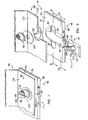
- means for attachment 42 of the CMC hotsheet 38 to the backbone structure 40 includes a fastener 134, a washer 136, a spacer 138, at least one Belleville washer 140, and a nut 142.
- the fastener 134 includes a head portion 146 and a body portion 148 with the body portion including a plurality of threads 150.
- the fastener 134 passes through the attachment opening 61 and the countersink hole 62 formed within the CMC hotsheet 38.
- the fastener head portion 146 fits into the countersink hole 61.
- the washer 136 is sandwiched between the hotsheet 38 and the backbone structure 40 and supports the spacer 138.
- the spacer 138 includes a cylindrical portion 154 and a ring portion 156 extending outwardly from the cylindrical portion.
- the cylindrical portion 154 of the spacer is substantially adjacent to the fastener body 148 and the ring portion 156 extends radially outward from the backbone structure 40 defining a spacer gap 158 therebetween, as best seen in FIGS. 6-12.
- the length of the cylindrical portion 154 of the spacer 138 is greater than the thickness of the backbone structure 40 disposed therein to define the gap 158.
- At least one Belleville washer 140 is disposed radially outward from the spacer 138 with the nut 142 tightened to clamp all the components together against the hotsheet 38 to a predetermined preload condition for a relatively tight fit without any looseness between the hotsheet 38 and other components.
- the backbone structure 40 includes the plurality of backbone openings 64 to allow attachment of the backbone structure 40 onto the hotsheet 38.
- the backbone openings 64 proximate to the hinge assembly 36 are substantially round and sized to accommodate the body portion 148 of the fasteners 134, as seen in FIG. 11.
- the remaining backbone openings are formed as elongated slots to allow for movement of the backbone structure 40 relative to the hotsheet 38, as seen in FIG. 12.
- the backbone structure 40 is fixedly attached to the hotsheet at the fore portion 30 of the flap 26.
- the backbone structure 40 is free to translate axially as a result of thermal expansion toward the aft portion 32 of the flap 26.
- the temperature of the engine quickly rises from the ground ambient temperature to extreme high temperatures.
- the temperature of the gases 18 passing through the engine also rises resulting in extremely high temperatures and creates harsh environment for a majority of the gas turbine components.
- the hot gases 18 are exhausted through the exhaust nozzle 20 causing the divergent flap 26 to heat to very high temperatures.
- the hotsheet 38 is in contact with the exhaust gases 18 exiting the engine.
- the hotsheet 38 is specifically designed to withstand the hot temperatures.
- the CMC hotsheet is subjected to extremely high temperatures, the hotsheet does not expand a great deal due to the material properties of CMC.
- the metal backbone structure 40 is subject to greater thermal expansion.
- the plow 46 secured to the backbone structure, moves aft toward the trailing edge of the hotsheet 38.
- the offset 75 is bridged and is substantially eliminated.
- the plow outer surface 68 becomes substantially flush with the chamfered surface 60 and the external flap outer surface 28, as best seen in FIGS. 2 and 6.
- the extremely hot temperatures also cause the aft portion 32 of the hotsheet 38 to warp and deflect.
- the aft support 63 of the backbone structure 40 minimizes the deflection of the trailing edge 58 of the hotsheet 38. By minimizing deflection, contact between the plow inward edge 74 and the hotsheet 38 is also minimized.
- the dovetail slot 80 retains the fastener 94 therein.
- the recess 82 provides a locking feature to prevent rotation and translation of the fastener 94 with respect to the CMC sheet.
- the gap between the base portion of the fastener 94 and the dovetail slot 80 allows for thermal growth of the metal fastener without loading the CMC material.
- the Belleville washer can be placed between the nut and the feature to maintain preload when the parts thermally expand and to reduce the stiffness of the fastener assembly to minimize CMC stresses than can occur because of thermally induced tightening of the assembly.
- the plow fastener assembly 48 allows attachment of a CMC sheet onto a metal structure without forming a through hole opening in the CMC sheet. Such feature is particularly critical in stealth plane design where the outer surface of the plane must be fabricated from particular materials and must not include metal fasteners on the surface thereof. Additionally, this unique attachment provides a connection between the CMC material and metal structure without leakage since a need for holes or openings is eliminated. Furthermore, the fastener 94 is insulated from the hot side 50 of the CMC sheet 38, thereby maintaining integrity of the fastener.
- the plow fastener assembly 48 can be used to join any CMC material with metal structure. In one embodiment of the present invention, the plow 46 is attached to the backbone structure via the bracket 98, as shown in FIGS.
- the bracket 98 is fabricated from metal and can be easily attached to the backbone structure 40 subsequently by various conventional fastening means 160, such as rivets or bolts, as shown in FIGS. 5 and 6.
- various conventional fastening means 160 such as rivets or bolts, as shown in FIGS. 5 and 6.
- the bracket 98 provides a bridge between the CMC sheet and other components to which the bracket can be attached by use of conventional fastening techniques.
- the plow can be directly attached to the backbone structure 40.
- the bracket 98 is included between the plow portion and the backbone structure, the plow 46 could be directly attached to the backbone structure 46.
- the bracket 98 provides a bridge between the plow portion and the backbone structure, thereby enabling the plow via the bracket to be attached to any structure by various means of a conventional attachment.
- the plow fastener assembly 48 is disposed in one plane to accommodate for thermal expansion and minimize thermal stresses.
- the fastening means 160 attaching the bracket 98 to the backbone structure 40 are also disposed in such a plane to minimize any thermal stress.
- the backbone openings 64 formed as elongated slots and disposed within the backbone structure also allow the backbone structure 40 to thermally expand relative to the hotsheet 38, thereby moving the plow 46 toward the trailing edge 56 of the hotsheet.
- the means for attachment 42 allows attachment of the CMC material to other types of materials without damaging the CMC material while applying significant tightening force to the assembly.
- the metal of the backbone structure 46 is trapped between the spacer 138 and the washer 134 and all components are clamped together against the hotsheet 38 to a set preload for a tight fit without looseness between the CMC material and other components.
- the elongated slots 64 formed within the backbone structure 40 allow movement of the backbone structure relative to the hotsheet without introducing looseness to the attachment assembly 42.
- the Belleville washer 140 maintains preload and reduces the stiffness of the fastener assembly to minimize CMC stresses than can occur because of thermally induced tightening of the assembly.
- the spacer allows for the thermal growth of the backbone structure while maintaining a tight attachment of the assembly.
- the plow 46 bridges the gap between the hotsheet 38 and the external flap 24. This feature ensures a smooth overall contour of the engine to minimize detection of the plane.
- An additional advantage of the present invention is that the plow moves relative to the hotsheet 38 to bridge the offset 75 during the hot condition to further minimize detection of the plane.
- the plow portion 46 is fabricated from the CMC material. The plow portion, fabricated from the CMC material, minimizes signature of the plane. The features of the present invention also accommodate different rates of thermal expansion of CMC and metal components.
- the backbone openings 64 allow relative movement between the backbone structure 40 and the hotsheet 38, thereby accommodating different rates of thermal expansion of metal and CMC material and also allowing the plow 46 to be moved toward the trailing edge 56 of the hotsheet 38 to minimize even small gaps for further improving signature of a plane.
- Another advantage of the present invention is that the aft portion 63 minimizes deflection of the hotsheet 38.
- the bracket 98 allows attachment of the CMC sheet onto any material.
- the present invention overcomes the difficulty of fastening a CMC plow portion onto metal components.
- the plow fastener assembly 48 eliminates a need for forming through openings in the external surface of the engine and also compensates for different rates of thermal expansion between metal and CMC.
- One advantage of the means for attachment 42 is that the CMC panel can be tightened with significant force and still allow sliding motion between the CMC panel and the metal structure. Additionally, any rattling of the components within the opening is eliminated, therefore, minimizing degradation of the material and extending service life of the components.
- This fastening scheme not only attaches the CMC component to a dissimilar material component, but also accommodates any thermal growth mismatch and secures the CMC component under positive and negative pressure conditions. The fastening scheme permits sliding of the structure relative to the CMC panel to eliminate thermally induced stresses.
Landscapes
- Engineering & Computer Science (AREA)
- General Engineering & Computer Science (AREA)
- Mechanical Engineering (AREA)
- Chemical & Material Sciences (AREA)
- Health & Medical Sciences (AREA)
- Life Sciences & Earth Sciences (AREA)
- Food Science & Technology (AREA)
- Combustion & Propulsion (AREA)
- Physics & Mathematics (AREA)
- Transportation (AREA)
- Structural Engineering (AREA)
- Analytical Chemistry (AREA)
- Biochemistry (AREA)
- General Health & Medical Sciences (AREA)
- General Physics & Mathematics (AREA)
- Immunology (AREA)
- Pathology (AREA)
- Architecture (AREA)
- Pulmonology (AREA)
- Theoretical Computer Science (AREA)
- Radiology & Medical Imaging (AREA)
- Nuclear Medicine, Radiotherapy & Molecular Imaging (AREA)
- Medicinal Chemistry (AREA)
- Connection Of Plates (AREA)
- Turbine Rotor Nozzle Sealing (AREA)
- Vehicle Interior And Exterior Ornaments, Soundproofing, And Insulation (AREA)
- Vehicle Step Arrangements And Article Storage (AREA)
- Stored Programmes (AREA)
- Fire-Detection Mechanisms (AREA)
- Exhaust Gas After Treatment (AREA)
- Slide Fasteners, Snap Fasteners, And Hook Fasteners (AREA)
Applications Claiming Priority (2)
| Application Number | Priority Date | Filing Date | Title |
|---|---|---|---|
| US10/850,257 US7153054B2 (en) | 2004-05-20 | 2004-05-20 | Fastener assembly for attaching a non-metal component to a metal component |
| US850257 | 2004-05-20 |
Publications (2)
| Publication Number | Publication Date |
|---|---|
| EP1598562A1 true EP1598562A1 (de) | 2005-11-23 |
| EP1598562B1 EP1598562B1 (de) | 2007-08-01 |
Family
ID=34940602
Family Applications (1)
| Application Number | Title | Priority Date | Filing Date |
|---|---|---|---|
| EP05251687A Expired - Lifetime EP1598562B1 (de) | 2004-05-20 | 2005-03-18 | Befestigungsvorrichtung zum Anbringen eines nichtmetallischen Bauteils an einem metallischen Bauteil |
Country Status (11)
| Country | Link |
|---|---|
| US (1) | US7153054B2 (de) |
| EP (1) | EP1598562B1 (de) |
| JP (1) | JP2005330960A (de) |
| KR (1) | KR20060044365A (de) |
| AT (1) | ATE368806T1 (de) |
| AU (1) | AU2005201195A1 (de) |
| CA (1) | CA2500677A1 (de) |
| DE (1) | DE602005001799T2 (de) |
| NO (1) | NO20051420L (de) |
| SG (1) | SG117526A1 (de) |
| TW (1) | TW200538629A (de) |
Cited By (13)
| Publication number | Priority date | Publication date | Assignee | Title |
|---|---|---|---|---|
| WO2008083780A1 (de) * | 2006-12-22 | 2008-07-17 | Daimler Ag | Vorrichtung zur befestigung eines kunststoffteils an einem karosserieteil eines fahrzeugs |
| EP1930579A3 (de) * | 2006-11-30 | 2011-09-07 | United Technologies Corporation | Thermisch entkoppelter Strahlmischer |
| CH703656A1 (de) * | 2010-08-27 | 2012-02-29 | Alstom Technology Ltd | Von Heissgasen durchströmbarer Gehäusekörper mit innerem Hitzeschild. |
| WO2014004017A1 (en) * | 2012-06-30 | 2014-01-03 | General Electric Company | A ceramic matrix composite component and a method of attaching a static seal to a ceramic matrix composite component |
| EP2392814A3 (de) * | 2010-06-07 | 2015-02-18 | United Technologies Corporation | Verstellmechanismus einer Schubdüsenklappe |
| EP2944776A1 (de) * | 2014-05-12 | 2015-11-18 | Rohr, Inc. | Mittenkörperbefestigungssystem |
| EP3018305A1 (de) * | 2014-11-07 | 2016-05-11 | Rohr, Inc. | Schubdüsen-mittelkörperbefestigung |
| CN105937533A (zh) * | 2015-03-05 | 2016-09-14 | 伍鐌科技股份有限公司 | 快拆扣件 |
| EP3098459A1 (de) * | 2015-05-29 | 2016-11-30 | Airbus Operations Limited | Befestigungsvorrichtung |
| EP3275788A1 (de) * | 2016-07-27 | 2018-01-31 | The Boeing Company | Verschiebegelenkkits, systeme damit und zugehörige verfahren |
| US10978792B2 (en) | 2017-10-11 | 2021-04-13 | The Boeing Company | Thermal growth management of radome by boundary constraints |
| FR3115319A1 (fr) * | 2020-10-15 | 2022-04-22 | Safran Ceramics | Ensemble de turbine de turbomachine |
| EP4282751A1 (de) * | 2022-05-24 | 2023-11-29 | Airbus Operations GmbH | Lasteinführungssystem und verfahren zur herstellung eines lasteinführungssystems |
Families Citing this family (48)
| Publication number | Priority date | Publication date | Assignee | Title |
|---|---|---|---|---|
| US20080003078A1 (en) | 2006-05-02 | 2008-01-03 | United Technologies Corporation | Fastener |
| US7967562B2 (en) * | 2006-06-06 | 2011-06-28 | United Technologies Corporation | Ceramic matrix composite capped bolt attachment |
| US8556531B1 (en) | 2006-11-17 | 2013-10-15 | United Technologies Corporation | Simple CMC fastening system |
| US7722317B2 (en) * | 2007-01-25 | 2010-05-25 | Siemens Energy, Inc. | CMC to metal attachment mechanism |
| US8568091B2 (en) * | 2008-02-18 | 2013-10-29 | United Technologies Corporation | Gas turbine engine systems and methods involving blade outer air seals |
| GB0802938D0 (en) * | 2008-02-19 | 2008-03-26 | Airbus Uk Ltd | Clamped friction joint |
| DE102008028382B4 (de) | 2008-06-13 | 2021-09-09 | Volkswagen Ag | Befestigungssystem, mit einem ersten Bauteil, einem zweiten Bauteil und einem Befestigungselement |
| US8322983B2 (en) * | 2008-09-11 | 2012-12-04 | Siemens Energy, Inc. | Ceramic matrix composite structure |
| US8973375B2 (en) * | 2008-12-31 | 2015-03-10 | Rolls-Royce North American Technologies, Inc. | Shielding for a gas turbine engine component |
| US7988395B2 (en) * | 2009-01-23 | 2011-08-02 | Steffier Wayne S | Mechanical fastener system for high-temperature structural assemblies |
| US8251410B1 (en) * | 2009-04-20 | 2012-08-28 | Armorworks Enterprises LLC | Armor hold-down assembly |
| US20110016697A1 (en) * | 2009-07-21 | 2011-01-27 | Honeywell International Inc. | Method of preloading a coupling assembly |
| US8267003B1 (en) * | 2009-08-11 | 2012-09-18 | Armorworks Enterprises LLC | Blast resistant armor mounting hardware |
| US8510945B2 (en) * | 2009-12-22 | 2013-08-20 | Unison Industries, Llc | Method of mounting a heat exchanger in a gas turbine engine assembly |
| DE102010024419A1 (de) | 2010-06-19 | 2011-12-22 | Lisi Automotive Kkp Gmbh & Co. Kg | Verfahren zur Befestigung von einem ersten Bauteil an einem zweiten Bauteil eines Fahrzeugs sowie entsprechende Befestigungsvorrichtung |
| US9689418B2 (en) * | 2010-12-15 | 2017-06-27 | GM Global Technology Operations LLC | Reduced-corrosion fastened assembly |
| US9412493B2 (en) * | 2011-06-08 | 2016-08-09 | Hubbell Incorporated | Spacer assembly for conductor bundle |
| US9093202B2 (en) | 2011-06-08 | 2015-07-28 | Hubbell Incorporated | Elastomeric gripping member for spacer assembly |
| WO2013163510A1 (en) | 2012-04-27 | 2013-10-31 | General Electric Company | Connecting gas turbine engine annular members |
| US9422865B2 (en) | 2013-03-14 | 2016-08-23 | Rolls-Royce Corporation | Bi-metal fastener for thermal growth compensation |
| WO2014149108A1 (en) | 2013-03-15 | 2014-09-25 | Graves Charles B | Shell and tiled liner arrangement for a combustor |
| US9482491B1 (en) | 2013-05-31 | 2016-11-01 | Armorworks Holdings, Inc. | Detachable armor hold down |
| WO2015009384A1 (en) | 2013-07-16 | 2015-01-22 | United Technologies Corporation | Gas turbine engine with ceramic panel |
| US9932831B2 (en) * | 2014-05-09 | 2018-04-03 | United Technologies Corporation | High temperature compliant metallic elements for low contact stress ceramic support |
| CN105333456B (zh) * | 2014-07-31 | 2017-11-10 | 中国航发商用航空发动机有限责任公司 | 用于火焰筒的浮动壁瓦块及其浮动壁 |
| US10544819B2 (en) | 2014-09-05 | 2020-01-28 | United Technologies Corporation | Reduced windage fastener assembly for a gas turbine engine |
| US20160084283A1 (en) * | 2014-09-23 | 2016-03-24 | Carl L. Sisemore | Ablative Mechanical Fastener |
| US10422238B2 (en) | 2014-12-05 | 2019-09-24 | Rolls-Royce Corporation | Method to pilot using flexible profile |
| US10480321B2 (en) | 2014-12-05 | 2019-11-19 | Rolls-Royce Corporation | Attachment of piloting feature |
| CN107208678B (zh) * | 2015-01-22 | 2018-10-30 | 日产自动车株式会社 | 碳纤维强化树脂材料的紧固构造 |
| US9551456B2 (en) * | 2015-02-03 | 2017-01-24 | United Technologies Corporation | Belleville washer nut plate |
| US9845692B2 (en) | 2015-05-05 | 2017-12-19 | General Electric Company | Turbine component connection with thermally stress-free fastener |
| US10167885B2 (en) | 2016-03-21 | 2019-01-01 | United Technologies Corporation | Mechanical joint with a flanged retainer |
| JP6441283B2 (ja) * | 2016-10-12 | 2018-12-19 | 矢崎総業株式会社 | 固定構造、および、電気接続箱 |
| US20180149030A1 (en) * | 2016-11-30 | 2018-05-31 | Rolls-Royce Corporation | Turbine shroud with hanger attachment |
| FR3060675B1 (fr) | 2016-12-19 | 2019-03-29 | Nexter Systems | Dispositif de protection anti projections pour un moyen de fixation |
| US20180283695A1 (en) * | 2017-04-03 | 2018-10-04 | United Technologies Corporation | Combustion panel grommet |
| US10520197B2 (en) | 2017-06-01 | 2019-12-31 | General Electric Company | Single cavity trapped vortex combustor with CMC inner and outer liners |
| DE102018202968B4 (de) | 2018-02-28 | 2019-09-05 | Ford Global Technologies, Llc | Strukturverstärktes Hohlelement sowie eine dieses aufweisende Fahrzeugkarosserie |
| CN110388282B (zh) * | 2018-04-16 | 2020-09-08 | 中国航发商用航空发动机有限责任公司 | 陶瓷基复合材料排气喷管尾喷构件及包括其的发动机 |
| FR3083843B1 (fr) * | 2018-07-16 | 2020-07-17 | Gaztransport Et Technigaz | Installation de stockage de fluide |
| CN111622810B (zh) * | 2019-02-27 | 2022-05-24 | 中国航发商用航空发动机有限责任公司 | 连接装置、燃气涡轮发动机、连接件以及涡轮外环 |
| US11346555B2 (en) | 2019-10-08 | 2022-05-31 | Rolls-Royce Corporation | Combustor for a gas turbine engine with ceramic matrix composite heat shield |
| US11466855B2 (en) | 2020-04-17 | 2022-10-11 | Rolls-Royce North American Technologies Inc. | Gas turbine engine combustor with ceramic matrix composite liner |
| US11215065B2 (en) * | 2020-04-24 | 2022-01-04 | Rolls-Royce Corporation | Turbine shroud assembly with ceramic matrix composite components having stress-reduced pin attachment |
| EP3960987A1 (de) * | 2020-08-31 | 2022-03-02 | Siemens Energy Global GmbH & Co. KG | Rotoranordnung für einen rotor einer gasturbine und gasturbine mit einer solchen rotoranordnung |
| CN114857142B (zh) * | 2022-05-12 | 2023-05-05 | 中国航发四川燃气涡轮研究院 | 异材构件间的连接结构 |
| CN118548281B (zh) * | 2024-07-29 | 2024-09-20 | 江苏博诚金属制品有限公司 | 一种耐高温紧固件 |
Citations (3)
| Publication number | Priority date | Publication date | Assignee | Title |
|---|---|---|---|---|
| US4702503A (en) * | 1984-05-18 | 1987-10-27 | Daimler-Benz Aktiengesellschaft | Coupling between at least two members to be subjected to high thermal stress |
| GB2299391A (en) * | 1995-03-29 | 1996-10-02 | Rover Group | Fixing motor vehicle panels to mountings |
| US6092953A (en) * | 1997-02-19 | 2000-07-25 | Compagnie Plastic Omnium | Plastic part slidably mountable on a support |
Family Cites Families (6)
| Publication number | Priority date | Publication date | Assignee | Title |
|---|---|---|---|---|
| US2915152A (en) * | 1957-03-12 | 1959-12-01 | Thomas T Graham | Leak-proof bolt |
| BE628664A (de) * | 1962-02-21 | |||
| US4157725A (en) * | 1977-09-29 | 1979-06-12 | Textron Inc. | Fastener and captive frusto-conical washer assembly |
| US4232496A (en) * | 1979-04-30 | 1980-11-11 | Tridair Industries | Grommet assembly for composite panels |
| US5116158A (en) * | 1988-12-06 | 1992-05-26 | Allied-Signal Inc. | High temperature turbine engine structure |
| US5497616A (en) * | 1994-11-16 | 1996-03-12 | Rolls-Royce Inc. | High temperature mounting for stress relief of a dovetail |
-
2004
- 2004-05-20 US US10/850,257 patent/US7153054B2/en not_active Expired - Lifetime
-
2005
- 2005-03-14 CA CA002500677A patent/CA2500677A1/en not_active Abandoned
- 2005-03-17 SG SG200501614A patent/SG117526A1/en unknown
- 2005-03-18 KR KR1020050022460A patent/KR20060044365A/ko not_active Withdrawn
- 2005-03-18 JP JP2005078755A patent/JP2005330960A/ja active Pending
- 2005-03-18 DE DE602005001799T patent/DE602005001799T2/de not_active Expired - Lifetime
- 2005-03-18 EP EP05251687A patent/EP1598562B1/de not_active Expired - Lifetime
- 2005-03-18 AU AU2005201195A patent/AU2005201195A1/en not_active Abandoned
- 2005-03-18 NO NO20051420A patent/NO20051420L/no not_active Application Discontinuation
- 2005-03-18 AT AT05251687T patent/ATE368806T1/de not_active IP Right Cessation
- 2005-03-18 TW TW094108440A patent/TW200538629A/zh unknown
Patent Citations (3)
| Publication number | Priority date | Publication date | Assignee | Title |
|---|---|---|---|---|
| US4702503A (en) * | 1984-05-18 | 1987-10-27 | Daimler-Benz Aktiengesellschaft | Coupling between at least two members to be subjected to high thermal stress |
| GB2299391A (en) * | 1995-03-29 | 1996-10-02 | Rover Group | Fixing motor vehicle panels to mountings |
| US6092953A (en) * | 1997-02-19 | 2000-07-25 | Compagnie Plastic Omnium | Plastic part slidably mountable on a support |
Cited By (24)
| Publication number | Priority date | Publication date | Assignee | Title |
|---|---|---|---|---|
| EP1930579A3 (de) * | 2006-11-30 | 2011-09-07 | United Technologies Corporation | Thermisch entkoppelter Strahlmischer |
| WO2008083780A1 (de) * | 2006-12-22 | 2008-07-17 | Daimler Ag | Vorrichtung zur befestigung eines kunststoffteils an einem karosserieteil eines fahrzeugs |
| EP2392814A3 (de) * | 2010-06-07 | 2015-02-18 | United Technologies Corporation | Verstellmechanismus einer Schubdüsenklappe |
| CH703656A1 (de) * | 2010-08-27 | 2012-02-29 | Alstom Technology Ltd | Von Heissgasen durchströmbarer Gehäusekörper mit innerem Hitzeschild. |
| DE102011110660A1 (de) | 2010-08-27 | 2012-03-15 | Alstom Technology Ltd. | Von Heissgasen durchströmbarer Gehäusekörper mit innerem Hitzeschild |
| US9810154B2 (en) | 2010-08-27 | 2017-11-07 | Ansaldo Energia Ip Uk Limited | Casing body through which hot gases can flow and comprising an inner heat shield |
| CN104379536B (zh) * | 2012-06-30 | 2016-08-31 | 通用电气公司 | 陶瓷基质复合物构件和将静密封件附接至陶瓷基质复合物构件的方法 |
| WO2014004017A1 (en) * | 2012-06-30 | 2014-01-03 | General Electric Company | A ceramic matrix composite component and a method of attaching a static seal to a ceramic matrix composite component |
| CN104379536A (zh) * | 2012-06-30 | 2015-02-25 | 通用电气公司 | 陶瓷基质复合物构件和将静密封件附接至陶瓷基质复合物构件的方法 |
| US9732701B2 (en) | 2014-05-12 | 2017-08-15 | Rohr, Inc. | Center body attachment system |
| EP2944776A1 (de) * | 2014-05-12 | 2015-11-18 | Rohr, Inc. | Mittenkörperbefestigungssystem |
| US9784215B2 (en) | 2014-11-07 | 2017-10-10 | Rohr, Inc. | Exhaust nozzle center body attachment |
| EP3018305A1 (de) * | 2014-11-07 | 2016-05-11 | Rohr, Inc. | Schubdüsen-mittelkörperbefestigung |
| CN105937533B (zh) * | 2015-03-05 | 2019-03-12 | 伍鐌科技股份有限公司 | 快拆扣件 |
| CN105937533A (zh) * | 2015-03-05 | 2016-09-14 | 伍鐌科技股份有限公司 | 快拆扣件 |
| EP3098459A1 (de) * | 2015-05-29 | 2016-11-30 | Airbus Operations Limited | Befestigungsvorrichtung |
| US10731683B2 (en) | 2015-05-29 | 2020-08-04 | Airbus Operations Limited | Fastening device |
| EP3275788A1 (de) * | 2016-07-27 | 2018-01-31 | The Boeing Company | Verschiebegelenkkits, systeme damit und zugehörige verfahren |
| US10427776B2 (en) | 2016-07-27 | 2019-10-01 | The Boeing Company | Sliding joint kits, systems containing the same, and related methods |
| US10978792B2 (en) | 2017-10-11 | 2021-04-13 | The Boeing Company | Thermal growth management of radome by boundary constraints |
| EP3470328B1 (de) * | 2017-10-11 | 2022-01-26 | The Boeing Company | Wärmeausdehnungsverwaltung von radom durch grenzbeschränkungen |
| FR3115319A1 (fr) * | 2020-10-15 | 2022-04-22 | Safran Ceramics | Ensemble de turbine de turbomachine |
| EP4282751A1 (de) * | 2022-05-24 | 2023-11-29 | Airbus Operations GmbH | Lasteinführungssystem und verfahren zur herstellung eines lasteinführungssystems |
| US12441457B2 (en) | 2022-05-24 | 2025-10-14 | Airbus Operations Gmbh | Load introduction system and a method for manufacturing a load introduction system |
Also Published As
| Publication number | Publication date |
|---|---|
| NO20051420L (no) | 2005-11-21 |
| US7153054B2 (en) | 2006-12-26 |
| US20050260034A1 (en) | 2005-11-24 |
| SG117526A1 (en) | 2005-12-29 |
| DE602005001799D1 (de) | 2007-09-13 |
| DE602005001799T2 (de) | 2008-04-30 |
| JP2005330960A (ja) | 2005-12-02 |
| ATE368806T1 (de) | 2007-08-15 |
| AU2005201195A1 (en) | 2005-12-08 |
| CA2500677A1 (en) | 2005-11-20 |
| TW200538629A (en) | 2005-12-01 |
| NO20051420D0 (no) | 2005-03-18 |
| EP1598562B1 (de) | 2007-08-01 |
| KR20060044365A (ko) | 2006-05-16 |
Similar Documents
| Publication | Publication Date | Title |
|---|---|---|
| US7153054B2 (en) | Fastener assembly for attaching a non-metal component to a metal component | |
| US7581301B2 (en) | Method for attaching a non-metal component to a metal component | |
| EP1605152B1 (de) | Divergenzklappe für ein Gasturbinentriebwerk | |
| US11149576B2 (en) | Turbine shroud with ceramic matrix composite seal segments mounted to metallic carriers | |
| EP0623742B1 (de) | Dichtungseinrichtung für die Abgasdüse eines Gasturbinentriebwerks | |
| EP3744950B1 (de) | Hängerhitzeschild aus keramikmatrixkomposit | |
| JP4052376B2 (ja) | ガスタービンエンジン可変ノズルをシールする方法及び装置 | |
| US6658854B2 (en) | Methods and apparatus for retaining gas turbine engine nozzle basesheets | |
| JP3493764B2 (ja) | ジェットエンジン用アフタバーナのフラップ取付構造 | |
| US7302793B2 (en) | Methods and apparatus to reduce turbine engine nozzle basesheet stresses |
Legal Events
| Date | Code | Title | Description |
|---|---|---|---|
| PUAI | Public reference made under article 153(3) epc to a published international application that has entered the european phase |
Free format text: ORIGINAL CODE: 0009012 |
|
| AK | Designated contracting states |
Kind code of ref document: A1 Designated state(s): AT BE BG CH CY CZ DE DK EE ES FI FR GB GR HU IE IS IT LI LT LU MC NL PL PT RO SE SI SK TR |
|
| AX | Request for extension of the european patent |
Extension state: AL BA HR LV MK YU |
|
| 17P | Request for examination filed |
Effective date: 20051109 |
|
| AKX | Designation fees paid |
Designated state(s): AT BE BG CH CY CZ DE DK EE ES FI FR GB GR HU IE IS IT LI LT LU MC NL PL PT RO SE SI SK TR |
|
| GRAP | Despatch of communication of intention to grant a patent |
Free format text: ORIGINAL CODE: EPIDOSNIGR1 |
|
| GRAS | Grant fee paid |
Free format text: ORIGINAL CODE: EPIDOSNIGR3 |
|
| GRAA | (expected) grant |
Free format text: ORIGINAL CODE: 0009210 |
|
| AK | Designated contracting states |
Kind code of ref document: B1 Designated state(s): AT BE BG CH CY CZ DE DK EE ES FI FR GB GR HU IE IS IT LI LT LU MC NL PL PT RO SE SI SK TR |
|
| REG | Reference to a national code |
Ref country code: GB Ref legal event code: FG4D |
|
| REG | Reference to a national code |
Ref country code: CH Ref legal event code: EP |
|
| REG | Reference to a national code |
Ref country code: IE Ref legal event code: FG4D |
|
| REF | Corresponds to: |
Ref document number: 602005001799 Country of ref document: DE Date of ref document: 20070913 Kind code of ref document: P |
|
| PG25 | Lapsed in a contracting state [announced via postgrant information from national office to epo] |
Ref country code: LT Free format text: LAPSE BECAUSE OF FAILURE TO SUBMIT A TRANSLATION OF THE DESCRIPTION OR TO PAY THE FEE WITHIN THE PRESCRIBED TIME-LIMIT Effective date: 20070801 Ref country code: FI Free format text: LAPSE BECAUSE OF FAILURE TO SUBMIT A TRANSLATION OF THE DESCRIPTION OR TO PAY THE FEE WITHIN THE PRESCRIBED TIME-LIMIT Effective date: 20070801 Ref country code: ES Free format text: LAPSE BECAUSE OF FAILURE TO SUBMIT A TRANSLATION OF THE DESCRIPTION OR TO PAY THE FEE WITHIN THE PRESCRIBED TIME-LIMIT Effective date: 20071112 Ref country code: IS Free format text: LAPSE BECAUSE OF FAILURE TO SUBMIT A TRANSLATION OF THE DESCRIPTION OR TO PAY THE FEE WITHIN THE PRESCRIBED TIME-LIMIT Effective date: 20071201 Ref country code: BG Free format text: LAPSE BECAUSE OF FAILURE TO SUBMIT A TRANSLATION OF THE DESCRIPTION OR TO PAY THE FEE WITHIN THE PRESCRIBED TIME-LIMIT Effective date: 20071101 Ref country code: NL Free format text: LAPSE BECAUSE OF FAILURE TO SUBMIT A TRANSLATION OF THE DESCRIPTION OR TO PAY THE FEE WITHIN THE PRESCRIBED TIME-LIMIT Effective date: 20070801 |
|
| NLV1 | Nl: lapsed or annulled due to failure to fulfill the requirements of art. 29p and 29m of the patents act | ||
| REG | Reference to a national code |
Ref country code: CH Ref legal event code: PL |
|
| ET | Fr: translation filed | ||
| PG25 | Lapsed in a contracting state [announced via postgrant information from national office to epo] |
Ref country code: PL Free format text: LAPSE BECAUSE OF FAILURE TO SUBMIT A TRANSLATION OF THE DESCRIPTION OR TO PAY THE FEE WITHIN THE PRESCRIBED TIME-LIMIT Effective date: 20070801 Ref country code: AT Free format text: LAPSE BECAUSE OF FAILURE TO SUBMIT A TRANSLATION OF THE DESCRIPTION OR TO PAY THE FEE WITHIN THE PRESCRIBED TIME-LIMIT Effective date: 20070801 Ref country code: LI Free format text: LAPSE BECAUSE OF FAILURE TO SUBMIT A TRANSLATION OF THE DESCRIPTION OR TO PAY THE FEE WITHIN THE PRESCRIBED TIME-LIMIT Effective date: 20070801 Ref country code: CH Free format text: LAPSE BECAUSE OF FAILURE TO SUBMIT A TRANSLATION OF THE DESCRIPTION OR TO PAY THE FEE WITHIN THE PRESCRIBED TIME-LIMIT Effective date: 20070801 |
|
| PG25 | Lapsed in a contracting state [announced via postgrant information from national office to epo] |
Ref country code: BE Free format text: LAPSE BECAUSE OF FAILURE TO SUBMIT A TRANSLATION OF THE DESCRIPTION OR TO PAY THE FEE WITHIN THE PRESCRIBED TIME-LIMIT Effective date: 20070801 |
|
| PG25 | Lapsed in a contracting state [announced via postgrant information from national office to epo] |
Ref country code: DK Free format text: LAPSE BECAUSE OF FAILURE TO SUBMIT A TRANSLATION OF THE DESCRIPTION OR TO PAY THE FEE WITHIN THE PRESCRIBED TIME-LIMIT Effective date: 20070801 Ref country code: GR Free format text: LAPSE BECAUSE OF FAILURE TO SUBMIT A TRANSLATION OF THE DESCRIPTION OR TO PAY THE FEE WITHIN THE PRESCRIBED TIME-LIMIT Effective date: 20071102 |
|
| PG25 | Lapsed in a contracting state [announced via postgrant information from national office to epo] |
Ref country code: SK Free format text: LAPSE BECAUSE OF FAILURE TO SUBMIT A TRANSLATION OF THE DESCRIPTION OR TO PAY THE FEE WITHIN THE PRESCRIBED TIME-LIMIT Effective date: 20070801 Ref country code: PT Free format text: LAPSE BECAUSE OF FAILURE TO SUBMIT A TRANSLATION OF THE DESCRIPTION OR TO PAY THE FEE WITHIN THE PRESCRIBED TIME-LIMIT Effective date: 20080102 Ref country code: CZ Free format text: LAPSE BECAUSE OF FAILURE TO SUBMIT A TRANSLATION OF THE DESCRIPTION OR TO PAY THE FEE WITHIN THE PRESCRIBED TIME-LIMIT Effective date: 20070801 |
|
| PLBE | No opposition filed within time limit |
Free format text: ORIGINAL CODE: 0009261 |
|
| STAA | Information on the status of an ep patent application or granted ep patent |
Free format text: STATUS: NO OPPOSITION FILED WITHIN TIME LIMIT |
|
| PG25 | Lapsed in a contracting state [announced via postgrant information from national office to epo] |
Ref country code: SE Free format text: LAPSE BECAUSE OF FAILURE TO SUBMIT A TRANSLATION OF THE DESCRIPTION OR TO PAY THE FEE WITHIN THE PRESCRIBED TIME-LIMIT Effective date: 20071101 Ref country code: RO Free format text: LAPSE BECAUSE OF FAILURE TO SUBMIT A TRANSLATION OF THE DESCRIPTION OR TO PAY THE FEE WITHIN THE PRESCRIBED TIME-LIMIT Effective date: 20070801 |
|
| 26N | No opposition filed |
Effective date: 20080506 |
|
| PG25 | Lapsed in a contracting state [announced via postgrant information from national office to epo] |
Ref country code: MC Free format text: LAPSE BECAUSE OF NON-PAYMENT OF DUE FEES Effective date: 20080331 |
|
| PG25 | Lapsed in a contracting state [announced via postgrant information from national office to epo] |
Ref country code: IE Free format text: LAPSE BECAUSE OF NON-PAYMENT OF DUE FEES Effective date: 20080318 Ref country code: EE Free format text: LAPSE BECAUSE OF FAILURE TO SUBMIT A TRANSLATION OF THE DESCRIPTION OR TO PAY THE FEE WITHIN THE PRESCRIBED TIME-LIMIT Effective date: 20070801 |
|
| PG25 | Lapsed in a contracting state [announced via postgrant information from national office to epo] |
Ref country code: SI Free format text: LAPSE BECAUSE OF FAILURE TO SUBMIT A TRANSLATION OF THE DESCRIPTION OR TO PAY THE FEE WITHIN THE PRESCRIBED TIME-LIMIT Effective date: 20070801 |
|
| PG25 | Lapsed in a contracting state [announced via postgrant information from national office to epo] |
Ref country code: CY Free format text: LAPSE BECAUSE OF FAILURE TO SUBMIT A TRANSLATION OF THE DESCRIPTION OR TO PAY THE FEE WITHIN THE PRESCRIBED TIME-LIMIT Effective date: 20070801 |
|
| PGFP | Annual fee paid to national office [announced via postgrant information from national office to epo] |
Ref country code: FR Payment date: 20100324 Year of fee payment: 6 |
|
| PG25 | Lapsed in a contracting state [announced via postgrant information from national office to epo] |
Ref country code: HU Free format text: LAPSE BECAUSE OF FAILURE TO SUBMIT A TRANSLATION OF THE DESCRIPTION OR TO PAY THE FEE WITHIN THE PRESCRIBED TIME-LIMIT Effective date: 20080202 Ref country code: LU Free format text: LAPSE BECAUSE OF NON-PAYMENT OF DUE FEES Effective date: 20080318 |
|
| PG25 | Lapsed in a contracting state [announced via postgrant information from national office to epo] |
Ref country code: TR Free format text: LAPSE BECAUSE OF FAILURE TO SUBMIT A TRANSLATION OF THE DESCRIPTION OR TO PAY THE FEE WITHIN THE PRESCRIBED TIME-LIMIT Effective date: 20070801 |
|
| PG25 | Lapsed in a contracting state [announced via postgrant information from national office to epo] |
Ref country code: IT Free format text: LAPSE BECAUSE OF NON-PAYMENT OF DUE FEES Effective date: 20080331 |
|
| REG | Reference to a national code |
Ref country code: FR Ref legal event code: ST Effective date: 20111130 |
|
| PG25 | Lapsed in a contracting state [announced via postgrant information from national office to epo] |
Ref country code: FR Free format text: LAPSE BECAUSE OF NON-PAYMENT OF DUE FEES Effective date: 20110331 |
|
| REG | Reference to a national code |
Ref country code: DE Ref legal event code: R082 Ref document number: 602005001799 Country of ref document: DE Representative=s name: SCHMITT-NILSON SCHRAUD WAIBEL WOHLFROM PATENTA, DE |
|
| REG | Reference to a national code |
Ref country code: DE Ref legal event code: R082 Ref document number: 602005001799 Country of ref document: DE Representative=s name: SCHMITT-NILSON SCHRAUD WAIBEL WOHLFROM PATENTA, DE Ref country code: DE Ref legal event code: R081 Ref document number: 602005001799 Country of ref document: DE Owner name: UNITED TECHNOLOGIES CORP. (N.D.GES.D. STAATES , US Free format text: FORMER OWNER: UNITED TECHNOLOGIES CORP., HARTFORD, CONN., US |
|
| REG | Reference to a national code |
Ref country code: DE Ref legal event code: R081 Ref document number: 602005001799 Country of ref document: DE Owner name: RAYTHEON TECHNOLOGIES CORPORATION (N.D.GES.D.S, US Free format text: FORMER OWNER: UNITED TECHNOLOGIES CORP. (N.D.GES.D. STAATES DELAWARE), FARMINGTON, CONN., US |
|
| P01 | Opt-out of the competence of the unified patent court (upc) registered |
Effective date: 20230519 |
|
| PGFP | Annual fee paid to national office [announced via postgrant information from national office to epo] |
Ref country code: DE Payment date: 20240220 Year of fee payment: 20 Ref country code: GB Payment date: 20240220 Year of fee payment: 20 |
|
| REG | Reference to a national code |
Ref country code: DE Ref legal event code: R071 Ref document number: 602005001799 Country of ref document: DE |
|
| REG | Reference to a national code |
Ref country code: GB Ref legal event code: PE20 Expiry date: 20250317 |
|
| PG25 | Lapsed in a contracting state [announced via postgrant information from national office to epo] |
Ref country code: GB Free format text: LAPSE BECAUSE OF EXPIRATION OF PROTECTION Effective date: 20250317 |