EP1598574A1 - Eléments d'appui - Google Patents
Eléments d'appui Download PDFInfo
- Publication number
- EP1598574A1 EP1598574A1 EP05010086A EP05010086A EP1598574A1 EP 1598574 A1 EP1598574 A1 EP 1598574A1 EP 05010086 A EP05010086 A EP 05010086A EP 05010086 A EP05010086 A EP 05010086A EP 1598574 A1 EP1598574 A1 EP 1598574A1
- Authority
- EP
- European Patent Office
- Prior art keywords
- support
- rolling
- damper
- support surface
- supporting
- Prior art date
- Legal status (The legal status is an assumption and is not a legal conclusion. Google has not performed a legal analysis and makes no representation as to the accuracy of the status listed.)
- Granted
Links
- 238000005096 rolling process Methods 0.000 claims description 92
- 239000002184 metal Substances 0.000 claims description 5
- 230000001419 dependent effect Effects 0.000 claims description 4
- 230000009471 action Effects 0.000 claims description 3
- 230000013011 mating Effects 0.000 claims 1
- 210000000056 organ Anatomy 0.000 description 7
- 230000008901 benefit Effects 0.000 description 6
- 238000009825 accumulation Methods 0.000 description 4
- 238000013016 damping Methods 0.000 description 4
- 230000007704 transition Effects 0.000 description 4
- 230000006835 compression Effects 0.000 description 3
- 238000007906 compression Methods 0.000 description 3
- 239000012535 impurity Substances 0.000 description 3
- 230000004048 modification Effects 0.000 description 3
- 238000012986 modification Methods 0.000 description 3
- 239000002245 particle Substances 0.000 description 3
- 229910000677 High-carbon steel Inorganic materials 0.000 description 2
- 229920001971 elastomer Polymers 0.000 description 2
- 239000000806 elastomer Substances 0.000 description 2
- 238000005538 encapsulation Methods 0.000 description 2
- 239000000463 material Substances 0.000 description 2
- 230000002411 adverse Effects 0.000 description 1
- 238000013459 approach Methods 0.000 description 1
- 239000000969 carrier Substances 0.000 description 1
- 238000005266 casting Methods 0.000 description 1
- 238000010276 construction Methods 0.000 description 1
- 230000003292 diminished effect Effects 0.000 description 1
- 238000006073 displacement reaction Methods 0.000 description 1
- 238000009826 distribution Methods 0.000 description 1
- 230000000694 effects Effects 0.000 description 1
- 235000011389 fruit/vegetable juice Nutrition 0.000 description 1
- 230000003993 interaction Effects 0.000 description 1
- 239000007769 metal material Substances 0.000 description 1
- 230000002093 peripheral effect Effects 0.000 description 1
- 238000004513 sizing Methods 0.000 description 1
Images


Classifications
-
- F—MECHANICAL ENGINEERING; LIGHTING; HEATING; WEAPONS; BLASTING
- F16—ENGINEERING ELEMENTS AND UNITS; GENERAL MEASURES FOR PRODUCING AND MAINTAINING EFFECTIVE FUNCTIONING OF MACHINES OR INSTALLATIONS; THERMAL INSULATION IN GENERAL
- F16F—SPRINGS; SHOCK-ABSORBERS; MEANS FOR DAMPING VIBRATION
- F16F15/00—Suppression of vibrations in systems; Means or arrangements for avoiding or reducing out-of-balance forces, e.g. due to motion
- F16F15/10—Suppression of vibrations in rotating systems by making use of members moving with the system
- F16F15/12—Suppression of vibrations in rotating systems by making use of members moving with the system using elastic members or friction-damping members, e.g. between a rotating shaft and a gyratory mass mounted thereon
- F16F15/131—Suppression of vibrations in rotating systems by making use of members moving with the system using elastic members or friction-damping members, e.g. between a rotating shaft and a gyratory mass mounted thereon the rotating system comprising two or more gyratory masses
- F16F15/133—Suppression of vibrations in rotating systems by making use of members moving with the system using elastic members or friction-damping members, e.g. between a rotating shaft and a gyratory mass mounted thereon the rotating system comprising two or more gyratory masses using springs as elastic members, e.g. metallic springs
- F16F15/134—Wound springs
- F16F15/1343—Wound springs characterised by the spring mounting
- F16F15/13453—Additional guiding means for springs
Definitions
- the present invention relates to a support element for supporting a elastically deformable damper element of a damper element arrangement a torsional vibration damper on a primary side and / or a secondary side of the torsional vibration damper or at another elastically deformable damper element; comprising a roller arrangement, which is supported on a Ab geometricenanalysis and on a Supporting surface of the torsional vibration damper is movable.
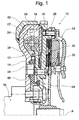
- FIGS. 1 and 2 show such a torsional vibration damper 10.
- This comprises a primary side 12 which is provided with a first cover disk element 14 on a drive shaft 16, for example, crankshaft set is and thus is rotatable with this about a rotation axis A.
- a radial outer, approximately axially extending portion 18 of the first Cover disk element 14 is a second cover disk element 20 firmly connected.
- the two cover disk elements 14 and 20 define radially outside a space portion 22, in which the damper elements 24, in general Helical compression springs, a damper element assembly 26 received are.
- the torsional vibration damper 10 further includes a secondary side 28.
- This has a central disk element 30, between the two Cover plate elements 14, 20 is positioned and with its radially outer Area in the space area 22 engages.
- Radially inside the cover disk element 20 is the central disk element 30 with a Flywheel member 32 firmly connected, which in turn to provide a friction clutch is coupled to a pressure plate assembly 34.
- At the central disk element 30 is further either as a separate component provided or integrally formed a hollow wheel-like toothing 36, the with a plurality of projections 38 of the cover disk member 14 rotatably supported Planetary gears 40 is in mesh.
- the damper elements 24 of the damper element assembly 26 are supported in the circumferential direction about below with reference to FIG. 2 in more detail described supporting elements on the primary side 12, d. H. the Cover plate elements 14, 20, as well as on the secondary side 28, d. H. at radially outwardly reaching arm portions 42 of the central disk element 30, from. In this way, a circumferential rotational movement the secondary side 28 with respect to the primary side 12 under compression of Damper elements 24, d. H. against their restoring effect, possible.
- the damper element assembly 26 two Groups of circumferentially successive damper springs 44, 46, 48, 50 and 52.
- the two groups almost extend each other over an angular range of 180 ° and are in their peripheral end, So on the springs 44 and 52, also referred to as spring plate support elements 54 on the arm portions 42 of the central disk element 30 and supported on the primary side 12 in the circumferential direction.
- the single ones Springs of the spring groups are relative to each other in the circumferential direction or approximately circumferentially supported by further support elements 56, commonly referred to as sliding shoes.
- the springs of the damper element assembly 26 have both the Support members 54 and the support members 56 each radially internal cross-supporting projections 60, 62 on.
- Both the support elements 54, so the spring plate, and the support elements 56, so the shoes, are supported radially outward a circumferentially extending support surface 58 at the approximate axially extending portion 18 of the cover disk element 14 off. In this way, a sliding or rubbing Support the individual springs 44, 46, 48, 50, 52 are avoided, although Spring groups provided with very large circumferential extent can be. It should be noted here that, as in FIG. 2 becomes clear, the individual springs in the spring groups to each other can be designed differently, so that in the individual Spring groups different damping characteristics are integrated can. Also nested springs can be provided.
- a damper element comprising a roller assembly which a Ab rangelementen emotions is supported and on a support surface of the Torsionsschwingungsdämpfers is movable, wherein the roller assembly at least one at least one support element on the Ab scopelementeneffort worn rolling element comprises.
- the Ab prolifelementen endeavor is made of plastic and that the support element made of metal.
- the structure of the Ab prolementen stresses Made of plastic ensures a very low weight and accordingly reduced flow juices, while the structure of the supporting elements made of metal for a high stability in the area of this burdened by the rolling organs themselves Components ensures.
- the at least one rolling element an axis and at least one roller bearing comprises on the axis.
- the Axle of the at least one rolling element on the Ab miclementenanalysis is carried over the at least one support element and that a Bearing outer ring of the at least one rolling bearing for movement on the support surface is trained.
- a support element for supporting a elastically deformable damper element of a damper element arrangement a torsional vibration damper on a primary side and / or a secondary side of the torsional vibration damper or at another elastically deformable damper element comprising a roller arrangement, which is supported on a Ab spanlementenanalysis and on a Supporting surface of the torsional vibration damper is movable, wherein the Roller arrangement at least one rolling element, preferably with an axis and at least one rolling bearing and wherein the axis or the at least one rolling bearing at least one for movement at the Has support surface provided roll area, wherein in the Ab miclementen redesign for the at least one roll area a this receiving and in the direction of movement of the support element at Movement along the support surface is essentially over the whole Ab miclementen emotions extending recess is provided.
- the axis of the at least one rolling element on the Ab maglementenanalysis is worn and a bearing outer ring of the at least one rolling bearing is provided for movement on the support surface.
- a bearing outer ring of at least a rolling bearing is carried on the Ab prolifelementenanalysis and that the Axis is designed for movement on the support surface.
- a support element for supporting a elastically deformable damper element of a damper element arrangement a torsional vibration damper on a primary side and / or a secondary side of the torsional vibration damper or at another elastically deformable damper element comprising a roller arrangement, which is supported on a Ab science and on a Supporting surface of the torsional vibration damper is movable, wherein the Roller assembly at least one rolling element with an axis and at least a rolling bearing, wherein the at least one rolling bearing a Bearing outer ring having respect to a plurality of rolling elements the axis is rotatably supported.
- the Axle of the at least one rolling element on the Ab maglementenanalysis is worn and the bearing outer ring of the at least one rolling bearing for Movement is provided on the support surface.
- the bearing outer ring of the at least one rolling bearing on the Ab monolementenanalysis is worn and that the axis to move the support surface is formed.
- a torsional vibration damper comprising a primary side and a against the action of a damper element assembly with respect to the primary side rotatable about a rotation axis Secondary side, wherein on the primary side and / or the secondary side in Circumferential direction about the axis of rotation extending Abstützf kaue is provided, along which at least one inventive support element with relative rotation between the primary side and the secondary side is movable, wherein on the support element at least one Gleitozo Scheme is provided, which centrifugally dependent inund out of contact with aellesgleit Jerusalem Kunststoff on the primary side and / or the secondary side can be brought.
- support member 56 comprises a made of plastic material Ab monolementenanalysis 64, which also the radially inwardly extending projection 62 for in Fig. 5 only schematically has indicated damper elements 24.
- the support body 64 is in the circumferential direction, ie in the direction of movement, in which this will move along the support surface 58 on the primary side 12, elongated.
- On the Ab prolementenanalysis is generally designated 66 Roll arrangement provided.
- FIG. 4 two at a distance from each other on Ab prolementenanalysis 64 provided Rolling organs 68, which are basically the same structure. It is important that in Fig. 5 shows an example of a support member 56 with three such rolling elements 68 is shown.
- Each of these rolling elements 68 comprises an axis 70, which has a sleeve-like Carrying member 72 is supported on the Ab molementenanalysis 64.
- the Carrying member 72 of a respective rolling element 68 is preferably made of high-carbon steel manufactured and on the Ab molementenanalysis 64 for example by Pinching firmly in an associated recess.
- the axis 70 in turn, fixed to the associated support member 72, d. H. not rotatable be worn.
- the axis 70 protrudes on both sides, ie in the view of FIG. 1 in the direction the axis of rotation A, via a central web portion 75 of the Ab prolementen stresses 64 out, or in which also the support elements 72 of the respective rolling members 68 are held.
- each this rolling bearing comprises a only schematically indicated in Fig. 4 Bearing outer ring 78, which has a plurality of rolling elements, for example Balls, tons, needles or the like on a bearing inner ring or directly to the associated axle 70 is worn.
- the bearing outer rings 78 are thus, by performing a rolling movement of the rolling elements on the Axles 70 rotatably supported.
- FIG. 3 and in FIG. 5 is the sizing of the rolling bearings so that they are above the central Stem portion 74 and projecting beyond the support elements 72 held in this and thus come into contact with the support surface 58.
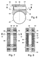
- FIGS. 6 and 7. A modified embodiment variant is shown in FIGS. 6 and 7. It can be seen here that on the support element body 64 no central Web portion is present, but a central recess 84, the is bounded on both sides by lateral web portions 86, 88.
- the axes 70 the rolling elements 68 are in their two lateral end regions now respectively via support elements 72 ', 72 "at these lateral web sections 86, 88 worn.
- each rolling element 68 again a roller bearing 90, which is now centrally located and, as in Fig. 6 can be seen over the web portions 86, 88 protrudes and thus in Can come into rolling contact with the support surface 58.
- the Burden the Ab nuclearenanalysis 64 thereby further mitigated that the support of the individual rolling elements 68 now over two of these each Assigned carrying elements 72 ', 72 "takes place continue the rolling bearings 90 of the individual rolling elements 68th laterally largely by the web portions 86, 88 and the support elements 72 ', 72 "are covered, even if not encapsulated are designed to reduce the risk of rolling bearings 90 becoming too dirty, significantly reduced.
- Fig. 8 is a further modification of that shown in Figs. 6 and 7 Embodiment shown.
- Fig. 8 is a single, for example, with U-shape designed carrying element 72 '' 'present. This contributes with each lateral wall portions 92, 94, the axes 70 of the rolling elements 68 and is in corresponding recesses of the Ab racelementen stresses 64 or the lateral web portions 86, 88 inserted and therein, for example, under Clamping action held.
- support elements 72, 72 ', 72 "and 72 '' 'already during the casting process of the support member body 64 there there to be installed.
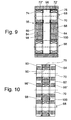
- FIG. One recognizes here that the Axes 70 of the rolling elements 68 in their lateral end regions, so in the Area of the web portions 86, 88 lying areas, now on the Rolling bearings 74, 76 are carried on Ab hardlementenanalysis 64. There are the roller bearings 74, 76 now in the bush or sleeve-like designed Carrying elements 72 ', 72 "used and on this on Ab monolementenanalysis 64 worn.
- the bearing outer rings of the roller bearings 74, 76 are thus fixed and substantially non-rotatable on Ab rangelementenanalysis 64 worn while now, the axes 70 are rotatable and with a lying in the region of the recess 84, radially expanded roll area 96th via the support element body 64 for contact with the support surface 58 protrude.
- the dimensioning of the roll area 96 may be such the roller bearings 74, 76 are completely separated from the support elements 72 "and 72 '. can be encapsulated.
- Material of the web sections 86, 88 contributes to the encapsulation of the rolling bearings 74, 76 at.
- the rolling bearings 74, 76 are covered by plate-like cover members 98, 100, so that in this way a complete encapsulation of rolling bearings 74, 76 can be obtained.
- the Ab magnetic resonanceenanalysis 64 turn the central web portion 74 and both sides of which the recesses 80, 82 on.
- a central roller bearing 90 On the axes 70 of the rolling elements 68 is again provided a central roller bearing 90, which in this embodiment variant is worn directly on Ab monomericenanalysis, of course but also on the support elements described above can be worn there.
- protruding Areas carry the axes 70 constructed of separate parts, for example plugged roll areas 96 ', 96 ", for example formed by Metal sleeves or the like. Again, so there is the rolling motion in Transition between the axes 70 and the respectively associated rolling bearing or in the transition between the rolling areas 96 'and 96 "and the Support surface 58 instead.
- the centrally positioned roller bearings 90 are through the central web portion 75 of the Ab monolementen stresses 64 and the on both sides of the same positioned cover plates 98, 100 completely again capsuled.
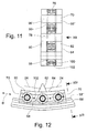
- FIG. 11 A further modification of this embodiment is shown in FIG. 11. You can see here again in the central web section 75 directly or possibly supported on supporting elements central roller bearing 90, over which the Axles 70 are carried on the Ab 100lementenanalysis.
- the cover plates 98, 100 are, for example, via pin-like clip connections 102 to the worn on both sides of the central web portion 75.
- the two roll areas 96 ', 96 are now provided directly to the axles 70.
- FIGS. 9 to 11 have the advantage on that, due to the fact that in general the rolling bearings 74, 76 and 90 have a larger outer diameter than the associated axes 70, already by supporting the rolling elements 68th on the roller bearings on Ab prolementen stresses 64 a much lower Surface pressure can be obtained. That's why, for example in the embodiments according to FIGS. 10 and 11 no additional support elements are shown, via which the support takes place. Rather, in these embodiments, the bearing outer shell 78 of the respective roller bearings as the function of a support member be taken over the accepting component.
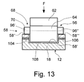
- FIG. 12 Another aspect of the support elements according to the invention or one with This designed torsional vibration damper is below with Referring to FIG. 12, for example, the one shown in FIG Support element is used. It should be noted that Of course, the principles explained below also in conjunction with the previously described, differently designed Supporting elements 56 and of course the recognizable in Fig. 2 Supporting elements 54 can be realized. This functionality will continue also explained with reference to FIG. 13.
- the support surface 58 here in three support surface areas 58 ', 58 "and 58' '' is divided is U-shaped and the two support surface areas 58 'and 58' '' act with the rolling members 68 together to the previously described rolling motion with relative rotation between the primary side and the secondary side to obtain a torsional vibration damper.
- the support surface areas 58 "and 58 ''' 'at the support surface area 58 'having component via resiliently effective carrier 104, 106 are worn.
- These carriers 104, 106 can, for example, by Elastomer layers, elastomer blocks, spring elements, such as helical compression springs, Corrugated metal spring or the like may be formed.
- the Ab Groupen stresses 14 lies with a Gleit Jerusalem College 108 the Support surface area 58 'with a small distance from. in principle but is between this Gleitinci Scheme 108 and the one GegenGleit Jerusalem College providing support surface area 58 'a distance available. Now moving at comparatively low speeds Supporting element 56 in the circumferential direction, ie in the direction of movement B in FIG. 12, this will initially be a rolling motion. But it is increasing Speed also the centrifugal force F, so are the carrier 104, 106th increasingly compressed and the Gleit Jerusalem Colour Society 108 approaches the Support surface area 58 'on. At a certain limit speed or Border centrifugal force, these two surface areas in mutual Contact us.
- Vibration damping critical low speed ranges will be the Occurrence of excessive friction avoided.
- torsional vibrations are not critical or, if they occur at all, only diminished or not undertaken at all will be for a discharge of those system areas taken care of otherwise for a suitable low-friction rolling motion to care.
Landscapes
- Engineering & Computer Science (AREA)
- General Engineering & Computer Science (AREA)
- Physics & Mathematics (AREA)
- Acoustics & Sound (AREA)
- Aviation & Aerospace Engineering (AREA)
- Mechanical Engineering (AREA)
- Rolling Contact Bearings (AREA)
- Devices For Conveying Motion By Means Of Endless Flexible Members (AREA)
- Vibration Prevention Devices (AREA)
- Rolls And Other Rotary Bodies (AREA)
- Rollers For Roller Conveyors For Transfer (AREA)
Applications Claiming Priority (2)
| Application Number | Priority Date | Filing Date | Title |
|---|---|---|---|
| DE102004024739 | 2004-05-19 | ||
| DE102004024739A DE102004024739A1 (de) | 2004-05-19 | 2004-05-19 | Abstützelement |
Publications (2)
| Publication Number | Publication Date |
|---|---|
| EP1598574A1 true EP1598574A1 (fr) | 2005-11-23 |
| EP1598574B1 EP1598574B1 (fr) | 2009-02-11 |
Family
ID=34936315
Family Applications (1)
| Application Number | Title | Priority Date | Filing Date |
|---|---|---|---|
| EP05010086A Expired - Lifetime EP1598574B1 (fr) | 2004-05-19 | 2005-05-10 | Eléments d'appui |
Country Status (3)
| Country | Link |
|---|---|
| EP (1) | EP1598574B1 (fr) |
| AT (1) | ATE422631T1 (fr) |
| DE (2) | DE102004024739A1 (fr) |
Cited By (2)
| Publication number | Priority date | Publication date | Assignee | Title |
|---|---|---|---|---|
| EP2031272A3 (fr) * | 2007-08-27 | 2010-07-28 | LuK Lamellen und Kupplungsbau Beteiligungs KG | Amortisseur de vibrations de torsions |
| EP1662173B2 (fr) † | 2004-11-30 | 2011-10-26 | Schaeffler Technologies AG & Co. KG | Amortisseur d'oscillations de torsion |
Families Citing this family (2)
| Publication number | Priority date | Publication date | Assignee | Title |
|---|---|---|---|---|
| DE102008017352A1 (de) | 2007-09-10 | 2009-03-12 | Magna Powertrain Ag & Co Kg | Zweimassenschwungrad |
| DE102017006247A1 (de) * | 2017-06-30 | 2019-01-03 | Borgwarner Inc. | Stützvorrichtung für eine Federanordnung eines Torsionsschwingungsdämpfers und Torsionsschwingungsdämpfer mit einer solchen Stützvorrichtung |
Citations (6)
| Publication number | Priority date | Publication date | Assignee | Title |
|---|---|---|---|---|
| DE2823894A1 (de) * | 1977-05-31 | 1978-12-14 | Borg Warner | Drehschwingungsdaempfer |
| EP0238231A2 (fr) * | 1986-03-18 | 1987-09-23 | Borg-Warner Automotive, Inc. | Amortisseur à longue courbe avec des moyens dynamiques de séparation des ressorts |
| DE19751029A1 (de) * | 1996-11-21 | 1998-05-28 | Valeo | Zweimassen-Dämpfungsschwungrad für Kraftfahrzeuge |
| DE10023113A1 (de) * | 2000-02-15 | 2001-08-16 | Mannesmann Sachs Ag | Antriebssystem |
| DE10241879A1 (de) * | 2001-09-17 | 2003-04-10 | Luk Lamellen & Kupplungsbau | Drehschwingungsdämpfer |
| DE102004006879A1 (de) * | 2003-02-14 | 2004-08-26 | Luk Lamellen Und Kupplungsbau Beteiligungs Kg | Drehschwingungsdämpfer |
-
2004
- 2004-05-19 DE DE102004024739A patent/DE102004024739A1/de not_active Withdrawn
-
2005
- 2005-05-10 EP EP05010086A patent/EP1598574B1/fr not_active Expired - Lifetime
- 2005-05-10 DE DE502005006590T patent/DE502005006590D1/de not_active Expired - Lifetime
- 2005-05-10 AT AT05010086T patent/ATE422631T1/de not_active IP Right Cessation
Patent Citations (6)
| Publication number | Priority date | Publication date | Assignee | Title |
|---|---|---|---|---|
| DE2823894A1 (de) * | 1977-05-31 | 1978-12-14 | Borg Warner | Drehschwingungsdaempfer |
| EP0238231A2 (fr) * | 1986-03-18 | 1987-09-23 | Borg-Warner Automotive, Inc. | Amortisseur à longue courbe avec des moyens dynamiques de séparation des ressorts |
| DE19751029A1 (de) * | 1996-11-21 | 1998-05-28 | Valeo | Zweimassen-Dämpfungsschwungrad für Kraftfahrzeuge |
| DE10023113A1 (de) * | 2000-02-15 | 2001-08-16 | Mannesmann Sachs Ag | Antriebssystem |
| DE10241879A1 (de) * | 2001-09-17 | 2003-04-10 | Luk Lamellen & Kupplungsbau | Drehschwingungsdämpfer |
| DE102004006879A1 (de) * | 2003-02-14 | 2004-08-26 | Luk Lamellen Und Kupplungsbau Beteiligungs Kg | Drehschwingungsdämpfer |
Cited By (2)
| Publication number | Priority date | Publication date | Assignee | Title |
|---|---|---|---|---|
| EP1662173B2 (fr) † | 2004-11-30 | 2011-10-26 | Schaeffler Technologies AG & Co. KG | Amortisseur d'oscillations de torsion |
| EP2031272A3 (fr) * | 2007-08-27 | 2010-07-28 | LuK Lamellen und Kupplungsbau Beteiligungs KG | Amortisseur de vibrations de torsions |
Also Published As
| Publication number | Publication date |
|---|---|
| DE102004024739A1 (de) | 2005-12-15 |
| EP1598574B1 (fr) | 2009-02-11 |
| ATE422631T1 (de) | 2009-02-15 |
| DE502005006590D1 (de) | 2009-03-26 |
Similar Documents
| Publication | Publication Date | Title |
|---|---|---|
| DE102015201257B3 (de) | Kugelgewindetrieb und zugehöriger elektromechanischer Aktuator | |
| EP2954233B1 (fr) | Palier de satellite dans un train planétaire | |
| DE19833436B4 (de) | Nabeneinheit-Komplettlager und Verfahren zur Herstellung desselben | |
| EP2651745B1 (fr) | Direction assistée munie d'un mécanisme à broche | |
| EP2986485B1 (fr) | Double rondelle ondulée comprenant une couche intermédiaire d'amortissement | |
| DE10241879A1 (de) | Drehschwingungsdämpfer | |
| WO2008052691A1 (fr) | Transmission | |
| EP2561245A1 (fr) | Capuchon de butée | |
| DE102005034739A1 (de) | Lagerung eines schwenkbaren Hebels | |
| DE3906079C2 (de) | Elastischer Aufhängepuffer | |
| DE102007016744A1 (de) | Torsionsschwingungsdämpfer | |
| DE19781289B4 (de) | Getriebe mit Lageranordnung | |
| DE102007018807A1 (de) | Käfig für ein Wälzlager | |
| DE69531687T2 (de) | Normal angelegte bremse | |
| DE102012101147A1 (de) | Stützlager mit Federelement | |
| EP2625442B1 (fr) | Roue libre à rouleaux de serrage pour un dispositif de réglage dans un véhicule automobile | |
| DE4203448A1 (de) | Riemenspannvorrichtung | |
| EP1598574B1 (fr) | Eléments d'appui | |
| EP2530344B1 (fr) | Élément de roulement d'une articulation de trépied ainsi qu'articulation de trépied comprenant un tel élément de roulement | |
| WO2018029075A1 (fr) | Ensemble palier rotatif conçu pour une colonne de direction d'un véhicule automobile | |
| EP1812723B1 (fr) | Rouleau tripode | |
| DE10311851B4 (de) | Schwenklagerung | |
| DE102017101038B4 (de) | Axiallager zur Lagerung eines Achsschenkels sowie Achsschenkellageranordnung mit dem Axiallager | |
| DE3430122A1 (de) | Federelement aus kunststoff | |
| EP1598575B1 (fr) | Amortisseur de vibrations en torsion |
Legal Events
| Date | Code | Title | Description |
|---|---|---|---|
| PUAI | Public reference made under article 153(3) epc to a published international application that has entered the european phase |
Free format text: ORIGINAL CODE: 0009012 |
|
| 17P | Request for examination filed |
Effective date: 20050802 |
|
| AK | Designated contracting states |
Kind code of ref document: A1 Designated state(s): AT BE BG CH CY CZ DE DK EE ES FI FR GB GR HU IE IS IT LI LT LU MC NL PL PT RO SE SI SK TR |
|
| AX | Request for extension of the european patent |
Extension state: AL BA HR LV MK YU |
|
| AKX | Designation fees paid |
Designated state(s): AT BE BG CH CY CZ DE DK EE ES FI FR GB GR HU IE IS IT LI LT LU MC NL PL PT RO SE SI SK TR |
|
| 17Q | First examination report despatched |
Effective date: 20060117 |
|
| GRAP | Despatch of communication of intention to grant a patent |
Free format text: ORIGINAL CODE: EPIDOSNIGR1 |
|
| GRAS | Grant fee paid |
Free format text: ORIGINAL CODE: EPIDOSNIGR3 |
|
| GRAA | (expected) grant |
Free format text: ORIGINAL CODE: 0009210 |
|
| AK | Designated contracting states |
Kind code of ref document: B1 Designated state(s): AT BE BG CH CY CZ DE DK EE ES FI FR GB GR HU IE IS IT LI LT LU MC NL PL PT RO SE SI SK TR |
|
| REG | Reference to a national code |
Ref country code: GB Ref legal event code: FG4D Free format text: NOT ENGLISH |
|
| REG | Reference to a national code |
Ref country code: CH Ref legal event code: EP |
|
| REG | Reference to a national code |
Ref country code: IE Ref legal event code: FG4D Free format text: LANGUAGE OF EP DOCUMENT: GERMAN |
|
| REF | Corresponds to: |
Ref document number: 502005006590 Country of ref document: DE Date of ref document: 20090326 Kind code of ref document: P |
|
| PG25 | Lapsed in a contracting state [announced via postgrant information from national office to epo] |
Ref country code: FI Free format text: LAPSE BECAUSE OF FAILURE TO SUBMIT A TRANSLATION OF THE DESCRIPTION OR TO PAY THE FEE WITHIN THE PRESCRIBED TIME-LIMIT Effective date: 20090211 Ref country code: SI Free format text: LAPSE BECAUSE OF FAILURE TO SUBMIT A TRANSLATION OF THE DESCRIPTION OR TO PAY THE FEE WITHIN THE PRESCRIBED TIME-LIMIT Effective date: 20090211 Ref country code: ES Free format text: LAPSE BECAUSE OF FAILURE TO SUBMIT A TRANSLATION OF THE DESCRIPTION OR TO PAY THE FEE WITHIN THE PRESCRIBED TIME-LIMIT Effective date: 20090522 Ref country code: LT Free format text: LAPSE BECAUSE OF FAILURE TO SUBMIT A TRANSLATION OF THE DESCRIPTION OR TO PAY THE FEE WITHIN THE PRESCRIBED TIME-LIMIT Effective date: 20090211 Ref country code: NL Free format text: LAPSE BECAUSE OF FAILURE TO SUBMIT A TRANSLATION OF THE DESCRIPTION OR TO PAY THE FEE WITHIN THE PRESCRIBED TIME-LIMIT Effective date: 20090211 |
|
| NLV1 | Nl: lapsed or annulled due to failure to fulfill the requirements of art. 29p and 29m of the patents act | ||
| PG25 | Lapsed in a contracting state [announced via postgrant information from national office to epo] |
Ref country code: IS Free format text: LAPSE BECAUSE OF FAILURE TO SUBMIT A TRANSLATION OF THE DESCRIPTION OR TO PAY THE FEE WITHIN THE PRESCRIBED TIME-LIMIT Effective date: 20090611 Ref country code: SE Free format text: LAPSE BECAUSE OF FAILURE TO SUBMIT A TRANSLATION OF THE DESCRIPTION OR TO PAY THE FEE WITHIN THE PRESCRIBED TIME-LIMIT Effective date: 20090511 Ref country code: PL Free format text: LAPSE BECAUSE OF FAILURE TO SUBMIT A TRANSLATION OF THE DESCRIPTION OR TO PAY THE FEE WITHIN THE PRESCRIBED TIME-LIMIT Effective date: 20090211 |
|
| REG | Reference to a national code |
Ref country code: IE Ref legal event code: FD4D |
|
| PG25 | Lapsed in a contracting state [announced via postgrant information from national office to epo] |
Ref country code: CZ Free format text: LAPSE BECAUSE OF FAILURE TO SUBMIT A TRANSLATION OF THE DESCRIPTION OR TO PAY THE FEE WITHIN THE PRESCRIBED TIME-LIMIT Effective date: 20090211 Ref country code: EE Free format text: LAPSE BECAUSE OF FAILURE TO SUBMIT A TRANSLATION OF THE DESCRIPTION OR TO PAY THE FEE WITHIN THE PRESCRIBED TIME-LIMIT Effective date: 20090211 Ref country code: DK Free format text: LAPSE BECAUSE OF FAILURE TO SUBMIT A TRANSLATION OF THE DESCRIPTION OR TO PAY THE FEE WITHIN THE PRESCRIBED TIME-LIMIT Effective date: 20090211 Ref country code: IE Free format text: LAPSE BECAUSE OF FAILURE TO SUBMIT A TRANSLATION OF THE DESCRIPTION OR TO PAY THE FEE WITHIN THE PRESCRIBED TIME-LIMIT Effective date: 20090211 Ref country code: PT Free format text: LAPSE BECAUSE OF FAILURE TO SUBMIT A TRANSLATION OF THE DESCRIPTION OR TO PAY THE FEE WITHIN THE PRESCRIBED TIME-LIMIT Effective date: 20090713 |
|
| BERE | Be: lapsed |
Owner name: ZF FRIEDRICHSHAFEN A.G. Effective date: 20090531 |
|
| PG25 | Lapsed in a contracting state [announced via postgrant information from national office to epo] |
Ref country code: SK Free format text: LAPSE BECAUSE OF FAILURE TO SUBMIT A TRANSLATION OF THE DESCRIPTION OR TO PAY THE FEE WITHIN THE PRESCRIBED TIME-LIMIT Effective date: 20090211 Ref country code: RO Free format text: LAPSE BECAUSE OF FAILURE TO SUBMIT A TRANSLATION OF THE DESCRIPTION OR TO PAY THE FEE WITHIN THE PRESCRIBED TIME-LIMIT Effective date: 20090211 |
|
| PGFP | Annual fee paid to national office [announced via postgrant information from national office to epo] |
Ref country code: GB Payment date: 20090506 Year of fee payment: 5 |
|
| PLBE | No opposition filed within time limit |
Free format text: ORIGINAL CODE: 0009261 |
|
| STAA | Information on the status of an ep patent application or granted ep patent |
Free format text: STATUS: NO OPPOSITION FILED WITHIN TIME LIMIT |
|
| PG25 | Lapsed in a contracting state [announced via postgrant information from national office to epo] |
Ref country code: MC Free format text: LAPSE BECAUSE OF NON-PAYMENT OF DUE FEES Effective date: 20090531 |
|
| REG | Reference to a national code |
Ref country code: CH Ref legal event code: PL |
|
| 26N | No opposition filed |
Effective date: 20091112 |
|
| PG25 | Lapsed in a contracting state [announced via postgrant information from national office to epo] |
Ref country code: CH Free format text: LAPSE BECAUSE OF NON-PAYMENT OF DUE FEES Effective date: 20090531 Ref country code: BG Free format text: LAPSE BECAUSE OF FAILURE TO SUBMIT A TRANSLATION OF THE DESCRIPTION OR TO PAY THE FEE WITHIN THE PRESCRIBED TIME-LIMIT Effective date: 20090511 Ref country code: LI Free format text: LAPSE BECAUSE OF NON-PAYMENT OF DUE FEES Effective date: 20090531 |
|
| PG25 | Lapsed in a contracting state [announced via postgrant information from national office to epo] |
Ref country code: BE Free format text: LAPSE BECAUSE OF NON-PAYMENT OF DUE FEES Effective date: 20090531 |
|
| PG25 | Lapsed in a contracting state [announced via postgrant information from national office to epo] |
Ref country code: AT Free format text: LAPSE BECAUSE OF NON-PAYMENT OF DUE FEES Effective date: 20090510 |
|
| PG25 | Lapsed in a contracting state [announced via postgrant information from national office to epo] |
Ref country code: GR Free format text: LAPSE BECAUSE OF FAILURE TO SUBMIT A TRANSLATION OF THE DESCRIPTION OR TO PAY THE FEE WITHIN THE PRESCRIBED TIME-LIMIT Effective date: 20090512 |
|
| GBPC | Gb: european patent ceased through non-payment of renewal fee |
Effective date: 20100510 |
|
| PG25 | Lapsed in a contracting state [announced via postgrant information from national office to epo] |
Ref country code: IT Free format text: LAPSE BECAUSE OF FAILURE TO SUBMIT A TRANSLATION OF THE DESCRIPTION OR TO PAY THE FEE WITHIN THE PRESCRIBED TIME-LIMIT Effective date: 20090211 |
|
| PG25 | Lapsed in a contracting state [announced via postgrant information from national office to epo] |
Ref country code: LU Free format text: LAPSE BECAUSE OF NON-PAYMENT OF DUE FEES Effective date: 20090510 |
|
| PG25 | Lapsed in a contracting state [announced via postgrant information from national office to epo] |
Ref country code: HU Free format text: LAPSE BECAUSE OF FAILURE TO SUBMIT A TRANSLATION OF THE DESCRIPTION OR TO PAY THE FEE WITHIN THE PRESCRIBED TIME-LIMIT Effective date: 20090812 |
|
| PG25 | Lapsed in a contracting state [announced via postgrant information from national office to epo] |
Ref country code: GB Free format text: LAPSE BECAUSE OF NON-PAYMENT OF DUE FEES Effective date: 20100510 |
|
| PGFP | Annual fee paid to national office [announced via postgrant information from national office to epo] |
Ref country code: FR Payment date: 20110523 Year of fee payment: 7 |
|
| PG25 | Lapsed in a contracting state [announced via postgrant information from national office to epo] |
Ref country code: TR Free format text: LAPSE BECAUSE OF FAILURE TO SUBMIT A TRANSLATION OF THE DESCRIPTION OR TO PAY THE FEE WITHIN THE PRESCRIBED TIME-LIMIT Effective date: 20090211 |
|
| PG25 | Lapsed in a contracting state [announced via postgrant information from national office to epo] |
Ref country code: CY Free format text: LAPSE BECAUSE OF FAILURE TO SUBMIT A TRANSLATION OF THE DESCRIPTION OR TO PAY THE FEE WITHIN THE PRESCRIBED TIME-LIMIT Effective date: 20090211 |
|
| PGFP | Annual fee paid to national office [announced via postgrant information from national office to epo] |
Ref country code: DE Payment date: 20110505 Year of fee payment: 7 |
|
| REG | Reference to a national code |
Ref country code: FR Ref legal event code: ST Effective date: 20130131 |
|
| REG | Reference to a national code |
Ref country code: DE Ref legal event code: R119 Ref document number: 502005006590 Country of ref document: DE Effective date: 20121201 |
|
| PG25 | Lapsed in a contracting state [announced via postgrant information from national office to epo] |
Ref country code: FR Free format text: LAPSE BECAUSE OF NON-PAYMENT OF DUE FEES Effective date: 20120531 |
|
| PG25 | Lapsed in a contracting state [announced via postgrant information from national office to epo] |
Ref country code: DE Free format text: LAPSE BECAUSE OF NON-PAYMENT OF DUE FEES Effective date: 20121201 |