EP1598575A1 - Amortisseur de vibrations de torsion - Google Patents
Amortisseur de vibrations de torsion Download PDFInfo
- Publication number
- EP1598575A1 EP1598575A1 EP05010087A EP05010087A EP1598575A1 EP 1598575 A1 EP1598575 A1 EP 1598575A1 EP 05010087 A EP05010087 A EP 05010087A EP 05010087 A EP05010087 A EP 05010087A EP 1598575 A1 EP1598575 A1 EP 1598575A1
- Authority
- EP
- European Patent Office
- Prior art keywords
- support
- torsional vibration
- vibration damper
- rolling
- damper according
- Prior art date
- Legal status (The legal status is an assumption and is not a legal conclusion. Google has not performed a legal analysis and makes no representation as to the accuracy of the status listed.)
- Granted
Links
- 238000005096 rolling process Methods 0.000 claims description 145
- 230000033001 locomotion Effects 0.000 claims description 69
- 210000000056 organ Anatomy 0.000 claims description 18
- 239000012530 fluid Substances 0.000 claims description 12
- 238000013461 design Methods 0.000 claims description 6
- 230000001419 dependent effect Effects 0.000 claims description 5
- 230000002093 peripheral effect Effects 0.000 claims description 5
- 230000009471 action Effects 0.000 claims description 3
- 230000002459 sustained effect Effects 0.000 claims description 2
- 230000006835 compression Effects 0.000 description 14
- 238000007906 compression Methods 0.000 description 14
- 238000010586 diagram Methods 0.000 description 9
- 229910052751 metal Inorganic materials 0.000 description 9
- 239000002184 metal Substances 0.000 description 8
- 238000013016 damping Methods 0.000 description 6
- 239000000463 material Substances 0.000 description 6
- 239000004033 plastic Substances 0.000 description 6
- 238000006073 displacement reaction Methods 0.000 description 5
- 230000000712 assembly Effects 0.000 description 4
- 238000000429 assembly Methods 0.000 description 4
- 230000003111 delayed effect Effects 0.000 description 4
- 230000003993 interaction Effects 0.000 description 4
- 230000013011 mating Effects 0.000 description 4
- 230000005540 biological transmission Effects 0.000 description 3
- 229920001971 elastomer Polymers 0.000 description 3
- 239000000806 elastomer Substances 0.000 description 3
- 230000007704 transition Effects 0.000 description 3
- 238000009825 accumulation Methods 0.000 description 2
- 238000013459 approach Methods 0.000 description 2
- 230000008901 benefit Effects 0.000 description 2
- 230000008859 change Effects 0.000 description 2
- 230000000694 effects Effects 0.000 description 2
- 230000004048 modification Effects 0.000 description 2
- 238000012986 modification Methods 0.000 description 2
- 230000035939 shock Effects 0.000 description 2
- 238000013519 translation Methods 0.000 description 2
- TVEXGJYMHHTVKP-UHFFFAOYSA-N 6-oxabicyclo[3.2.1]oct-3-en-7-one Chemical compound C1C2C(=O)OC1C=CC2 TVEXGJYMHHTVKP-UHFFFAOYSA-N 0.000 description 1
- 239000004809 Teflon Substances 0.000 description 1
- 229920006362 Teflon® Polymers 0.000 description 1
- 230000009286 beneficial effect Effects 0.000 description 1
- 230000015572 biosynthetic process Effects 0.000 description 1
- 238000002485 combustion reaction Methods 0.000 description 1
- 238000010276 construction Methods 0.000 description 1
- 230000006735 deficit Effects 0.000 description 1
- 230000010354 integration Effects 0.000 description 1
- 239000010410 layer Substances 0.000 description 1
- 238000004519 manufacturing process Methods 0.000 description 1
- 239000007769 metal material Substances 0.000 description 1
- 238000000034 method Methods 0.000 description 1
- 230000000149 penetrating effect Effects 0.000 description 1
- 229920001343 polytetrafluoroethylene Polymers 0.000 description 1
- 239000004810 polytetrafluoroethylene Substances 0.000 description 1
- 238000003825 pressing Methods 0.000 description 1
- 230000009467 reduction Effects 0.000 description 1
- 238000007789 sealing Methods 0.000 description 1
- 230000035945 sensitivity Effects 0.000 description 1
- 238000010025 steaming Methods 0.000 description 1
- 239000000725 suspension Substances 0.000 description 1
- 238000012549 training Methods 0.000 description 1
- 230000001960 triggered effect Effects 0.000 description 1
- 239000002347 wear-protection layer Substances 0.000 description 1
Images





Classifications
-
- F—MECHANICAL ENGINEERING; LIGHTING; HEATING; WEAPONS; BLASTING
- F16—ENGINEERING ELEMENTS AND UNITS; GENERAL MEASURES FOR PRODUCING AND MAINTAINING EFFECTIVE FUNCTIONING OF MACHINES OR INSTALLATIONS; THERMAL INSULATION IN GENERAL
- F16F—SPRINGS; SHOCK-ABSORBERS; MEANS FOR DAMPING VIBRATION
- F16F15/00—Suppression of vibrations in systems; Means or arrangements for avoiding or reducing out-of-balance forces, e.g. due to motion
- F16F15/10—Suppression of vibrations in rotating systems by making use of members moving with the system
- F16F15/12—Suppression of vibrations in rotating systems by making use of members moving with the system using elastic members or friction-damping members, e.g. between a rotating shaft and a gyratory mass mounted thereon
- F16F15/131—Suppression of vibrations in rotating systems by making use of members moving with the system using elastic members or friction-damping members, e.g. between a rotating shaft and a gyratory mass mounted thereon the rotating system comprising two or more gyratory masses
- F16F15/13128—Suppression of vibrations in rotating systems by making use of members moving with the system using elastic members or friction-damping members, e.g. between a rotating shaft and a gyratory mass mounted thereon the rotating system comprising two or more gyratory masses the damping action being at least partially controlled by centrifugal masses
Definitions
- the present invention relates to a torsional vibration damper comprising a primary side and one against the action of a damper element assembly with respect to the primary side rotatable about a rotation axis secondary side, wherein the Damper element arrangement for supporting radially outward with respect to Primary side or / and the secondary side associated with at least one support element is that on the primary side and / or the secondary side via a roller assembly is supported
- Such a torsional vibration damper is known from DE 197 51 029 A1.
- the supporting elements with which the successive in the circumferential direction Damper springs of a damper element arrangement on the one hand with respect to each other and on the other hand radially outward and with respect to the primary side and the Secondary side are supported, have a Ab geometricenanalysis which in a cavity receives an axis with a roll provided thereon. about the axle is rotatably carried by the roller on the support body.
- the Supporting elements are thus on the roles provided in a Rolling condition along one of the primary side and the secondary side formed support region movable.
- a torsional vibration damper comprising a primary side and one against the effect a damper element arrangement with respect to the primary side about an axis of rotation rotatable secondary side, wherein the damper element arrangement for support radially outward with respect to the primary side and / or the secondary side at least a support element is assigned to the primary side and / or the Secondary side is supported by a roller assembly and a Has sliding surface area, the centrifugal force dependent in and out of contact with a against sliding surface area on the primary side and / or the secondary side can be brought is.
- a relief of the roller assembly is created by the fact that in addition also a contact between a Supporting element and the primary side or secondary side is created by then slidably contacting each other with moving surface areas and thus provide additional support. With this additional Support, however, the roller assembly is relieved, so that a through Fliehkraftein Koch induced damage to the roller assembly or one of these having support member can be practically excluded.
- the roller assembly can be both by means of a rolling as well as by means of a Slide bearing be arranged on a preferably non-rotatable axis, wherein each results in a problem-free fit dimensioning with respect to the axis, and a low sensitivity to tribological influences, such as for example, the surface quality of a counter-Gleit vom Kunststoffs a Supporting area on primary side or secondary side.
- a particularly efficient effective embodiment can provide the centrifugal force-dependent switching between a rolling motion and a Sliding motion or combined rolling / sliding movement be provided that on the primary side and / or the secondary side in the circumferential direction around the Is provided axis of rotation extending supporting region along which the at least one support element is movable, wherein the support region a Rolling area and the counter Gleit vom Kunststoff Scheme provides and the Rolling surface area dependent on the centrifugal force with respect to the counter sliding surface area is relocatable.
- the rolling surface area at least one Rolling surface element comprises, on a support structure against the restoring force an elastic arrangement is carried substantially radially displaceable.
- the elastic arrangement a Provides restoring force, the one on the at least one support element acting centrifugal force is substantially opposite.
- a stable even under centrifugal force leadership of at least one Supporting element can be realized that the counter-Gleit perennial Scheme in the axial direction on both sides of the rolling surface area one each Surface section has. It can be provided that between the Surface portions of the counter-Gleit perennial Schemes one the at least one Rolling surface element and the elastic arrangement receiving recess is provided.
- the at least one support element be designed so that the roller assembly a Includes a plurality of rolling elements, which in circumferential movement of the at least a support member in a limited range of motion with respect to a Ab hydrolementen stresses of at least one support element in the Circumferential movement direction thereof are movable and upon reaching a End of the range of motion are blocked against further rolling motion.
- the Block the rolling elements against further rolling movement with respect to the Ab hydrolementen stressess and / or with respect to the support area on the Primary side or the secondary side has the consequence that, if continued Circumferential movement of the support element actually no more rolling motion will take place, but a sliding movement.
- the support elements can be further provided that the roller assembly with respect to the support area via a rolling carriage is supported and that when reaching the end of the range of motion and sustained circumferential movement of the at least one support element of this associated Abrollschlitten for performing a sliding movement along the Supporting area entrains.
- the rolling organs themselves before performing any of these may be excessively wearing Be protected sliding movement.
- the sliding movement is actually in transition take place between the rolling carriage and the primary side or the secondary side.
- the inventive Torsional vibration damper be designed so that the roller assembly at least one on a Ab rangelementenanalysis via an elastic assembly supported rolling element comprises, with which the at least one support element along a about the axis of rotation extending support area on the Primary side or / and the secondary side is movable, wherein the elastic Arrangement provides a restoring force, which the Ab forlementenanalysis with the provided Gleit perennial Scheme against centrifugal force except Plain contact with the counter Gleit perennial Kunststoff providing Supporting area stops.
- the roller assembly at least one on a Ab rangelementenanalysis via an elastic assembly supported rolling element comprises, with which the at least one support element along a about the axis of rotation extending support area on the Primary side or / and the secondary side is movable, wherein the elastic Arrangement provides a restoring force, which the Ab forlementenanalysis with the provided Gleitinci Scheme against centrifugal force except Plain contact with the counter Gleitbericht Scheme providing Supporting holds, preferably the vote of the elastic arrangement is selected such that provided by the elastic assembly Restoring force is sufficient to reach one on the Ab terminalen redesign acting limit centrifugal force and / or a limit speed the Sliding surface area except abutting contact with the counter Gleitbericht Scheme too hold.
- the at least a support element has a rolling surface region and the sliding surface region, which is carried over an elastic arrangement with respect to the rolling surface area, wherein the elastic arrangement of a centrifugal force on the Gleit vom Kunststoff Kunststoff counteracting restoring force provides.
- this is the Tuning of the elastic arrangement preferably such that by the elastic arrangement provided restoring force until reaching one on the Sliding surface area acting limit centrifugal force and / or a limit speed is sufficient to the Gleit Jerusalem Kunststoff contact with the provided on the support area against Gleit Jerusalem Kunststoff.
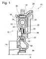
- Fig. 1 is a torsional vibration damper, generally also dual-mass flywheel called, designated 10.
- the torsional vibration damper 10 includes a primary side 12 connected to a drive shaft 14, for example a Crankshaft, for rotation about a rotation axis A connected or connectable.
- This primary side 12 in turn has a cover disk element 16 which is radial is to be connected internally to the drive shaft 14 and in a radially outer portion 18 is fixedly connected to a further cover disk element 20.
- the two Cover disk elements 18, 20 define a volume region 22 in which the in the circumferential direction successive damper elements 24, for example Helical compression springs, a generally designated 26 damper element assembly are included. Between the two cover disk elements 16, 20 is formed radially outwardly a conical space 28, in which deposits can accumulate.
- a secondary side 30 of the torsional vibration damper 10 includes a Central disk element 32. This engages radially outward into the volume region 22 Interaction with the damper elements 24 and is radially inward and axial mounted radially with respect to the primary side 12. Radial within the Cover disk element 20 is the central disk element 32 with a Flywheel 34 firmly connected to a pressure plate assembly one not can carry friction clutch shown further.
- the damper element assembly 26 may include a plurality of groups of damper elements 24, each of these groups then being circumferentially aligned following and supported by support members 36 mutually supported damper elements 24th includes.
- the section 18 of Cover disk element 16 generally designated 38 and subsequently formed in detail explained support area.
- FIG. 2 can be seen in an enlarged and somewhat simplified view the radial outer area of the primary side 12.
- Supporting element 36 This comprises a constructed example of plastic Ab hardness 40.
- two in the circumferential direction about the axis of rotation A successive rolling members 42 a generally 44th designated roller assembly provided.
- Each of these rolling elements 42 comprises an axis 46, which at its two lateral end portions in Support member body 40 is rotatably supported, and further comprises a Rolling area 48.
- This rolling area 48 may, for example, integral with the axis 46th be formed, but for example, but also a roller bearing 50 with a Outer bearing shell 52 which, via a plurality of rolling elements 54, For example, balls, tons or needles, is rotatably supported on the axle 46.
- the axially provided in the central region of the support member 36 Bearing outer shell 52 and the rolling area 48 is generally provided at Circumferential movement of the support element 36, which in a relative rotation between the primary side 12 and the secondary side 30 and the occurring Compression of the damper elements 24 will take place, a rolling motion on Execute supporting region 38, so that this circumferential movement as possible low resistance can take place.
- a rolling surface area 56 is provided, and on both axial sides of the rolling surface portion 56 are respectively Surface portions 58, 60 of a generally designated 62 counter Gleit vom Kunststoffs intended.
- the rolling surface area 56 and the sections 58, 60 of the counter-Gleit vom Kunststoff 62 extend in the circumferential direction around the Rotary axis A preferably completely continuous.
- the rolling surface area 56 substantially is formed by one or more plate-like rolling surface elements 64, which in one Recess 66 of the portion 18 of the cover plate member 16 added are.
- the rolling surface elements 64 are not based directly on the Section 18, but it is an elastic assembly 68 is provided, which this support performs such that in the unloaded state, for example, the Rolling surface area 56 in the radial direction flush with the two surface areas 58, 60 of the counter-Gleit Jerusalem Colour Council 62 is located.
- the elastic assembly 68 may be one or more circumferentially
- the following spring plate elements 70 have that provide a radial elasticity and thus allow the rolling surface elements 68 a certain radial movement.
- other elastic elements e.g. Elastomer layers, the ring-shaped Wellfederelement 72 shown in Fig. 3 or a plurality of helical compression springs or the like. be provided.
- the dimensioning of the support element 36 is such that the rolling region 58, So for example, the outer bearing shell 52 of the rolling bearing 50, the Rolling surface area 56 is opposite or rests there. On both sides this Rolling surface region 52 are located in sections 58, 60 of the opposing sliding surface region 62 surface portions 74, 76 of a Gleit vom Kunststoffs 78 of Support member 36 opposite, but with a radial distance, as in Fig. 2nd recognizable.
- the force acting on the rolling elements 42 load is thus limited by the moment of the generation of the contact system provided restoring force of the elastic assembly 68 and the individual Spring elements 70, 72 or the like. That is, continue to increase centrifugal forces only with increased contact pressure of the support element body 40 its sliding surface area 78 against the counter-sliding surface 62 of the Support area 38.
- the transition to the state, in addition to a sliding contact the support elements 36 is generated at the support area 38 be chosen so that this occurs in a state in which the on the rolling elements 42 and thus also the support member body 40 acting loads not yet damage to these system areas, and in which one is taken care that the then occurring additional sliding friction a significant impairment of the vibration damping characteristic not will cause.
- a torsional vibration damping is generally no longer required or one with reduced quality of torsional vibration damping loss of comfort practically will not result because not sufficient in this operating range damped vibrations are virtually imperceptible.
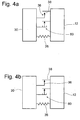
- Fig. 4 shows in their diagrams a) and b) in principle representation once the operation of the previously described torsional vibration damper 10. It can be seen schematically the primary side 12th and the secondary side 30 and the interposing damper element assembly 26. Next, one recognizes the embodiment shown in the illustrated on the primary side 12 designed support portion 38 and the Supporting elements 36.
- the diagram a) illustrates the state less Speed, ie the state in which a frictional interaction of the Supporting elements 36 with the support portion 38 is not yet available and only the rolling motion will take place.
- diagram b) is the state illustrates in which at then increased speed and correspondingly increased Centrifugal force the support members 36 in sliding friction contact with the support portion 38th occur and thus in addition to the rolling motion a Gleitreibungskomponente introduce and continue by the immediate support on the support portion 38 for to relieve the roller assembly.
- a generally designated 80 friction device For example, dry rubbing device.
- This ensures that through the Presence of an additional friction force component critical relative motion states between the primary side 12 and the secondary side 30 can be intercepted.
- These critical conditions can be used, for example Go through the resonance or the occurrence of load change states to a excessive deflection between primary side 12 and secondary side 30 lead. Due to the presence of an additional frictional force component of this Deflection counteracted. For example, this frictional force at the in Fig.
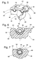
- a support member 36 In Fig. 5, an alternative embodiment of a support member 36 is shown. It recognizes the support body formed for example of plastic material 40 with the radially inwardly extending support projection 88, at which circumferentially immediately following damper elements 24 can support themselves.
- the roller assembly 44 here includes, for example, two Rolling organs 42 with their axes 46 and as already described above Rolling areas 48 or bearings 50 provided thereon.
- the axes 46 are not directly on the in this embodiment Ab prolementenanalysis 40 worn, but designed over half-shell-like Spring elements 90. These are with end legs 92, 94 in recesses of the Ab prolementen emotionss 40 worn and support with a shell portion 96th the axes 46.
- the spring elements 90 thus provide the elastic arrangement 68th ready, which now one of a centrifugal force on the Ab monolementen endeavor 40 provide counteracting restoring force.
- the Supporting region 38 for example, on the primary side 12 here comprises a For example, cylindrically shaped continuous surface in the axial roll the rolling areas 48 of the rolling elements 42 central area. Both sides and between the rolling regions 48 forms a surface of the Ab monolementen emotionss 40, the sliding surface area 78 thereof.
- FIG. 6 A modified embodiment of such a support element 36 is in Fig. 6 is shown. It can be seen here that in association with the individual rolling organs 36 recesses in the support element body 40 are formed, in which turn For example, formed from spring plate spring elements 90 are used. This in their entirety now providing the elastic assembly 68 Spring elements 90 have a v- or roof-like shape and are with their end legs 92, 94 on side walls of the axes 46 of the rolling organs 42 receiving recesses worn or fixed. Again, one can increasing centrifugal force on the support element body 40 below Deformation of the spring elements 90 to a radial displacement of the Ab spalementenoasa 40 with respect to the rolling elements 46 and thus also with respect of these still supporting support 38 lead on the primary side.
- the spring elements 90 are again in the sliding surface area 78 towards open recesses 98 in Ab rangelementenanalysis 40 used and are now considered to be about the axes 46th designed curved corrugated sheet metal elements. These are also under Fliehkraftein Koch deformable and thus allow the radial displacement of the Ab rangelementen stressess 40 with its Gleit vom Kunststoff Kunststoff 78 on the Supporting area 38 on the primary side too.
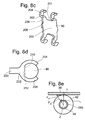
- a spring element 90 which has a central Connecting part 200 has, at the two-sided circumferential boundaries 201 in End legs 202 passes, to each of which a receptacle 204 for each axis 46 of a rolling element 42 is provided, wherein in each case two of these end legs 202, viewed in the axial direction, are spaced from each other. Furthermore, you will find yourself at the central connection part 200 between the two-sided circumferential boundaries 201, preferably in the middle between the same, tabs 206, extending in the axial direction each extend beyond an axial boundary 208 of the connecting part 200 addition.
- the spring element 90 forms with the rolling members 42 each one Roller assembly 44.
- the axis 46 of the respective rolling member 42 is rotatably in the receptacle 204th be arranged.
- the axis 46 can therefore be preferred in the corresponding Recordings 204 are pressed, where that creates a positive connection,
- it is also conceivable to produce a positive connection for which the Axis 204, as shown in Fig. 8d, formed with a geometric contour 210 is, which engages in a corresponding mating contour 212 of the receptacle 204.
- the Rolling members 42 can, in already shown for Fig. 2 way, by means of a Roller bearing be arranged on the respective axis 46. But it is the same conceivable, instead of Fig.
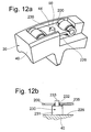
- a sliding bearing 250 which as sleeve-shaped element may be formed and with its radial inside the axis 46 is pressed and thus against the same rotation, while the Rolling member 42 with its radial inner side slidable on the radial outside of the Slide bearing 250 is arranged, with its radial outer side, however, on Sliding surface portion 78 of the support portion 38 of the primary side 12 or Secondary side 30 rolls, namely about its center of rotation Z.
- the rolling element 42 is loaded during a relative movement of the support member 36 relative to the support portion 38 on its radially outer side at a first location i1 in Fig. 8e with a circumferential force F U1 , which is a rolling movement of the rolling member 42 about the radial outer side of the sliding bearing 250 generated at a second location i2 between the radial inner side of the rolling member 42 and the radial outer side of the sliding bearing 250 a frictional sliding movement.
- the friction influence of this sliding movement is low, since there is a transmission ratio between the outer diameter of the rolling element 42 and the outer diameter of the plain bearing 250.
- the circumferential force F U2 is applied at the second location i2 with respect to the center of rotation Z.
- a sliding bearing 250 is also present when the rolling member 42 directly on the rotatably fixed shaft 46 is arranged. The translation then results from the Outer diameter of the rolling element 42 relative to the outer diameter of the Axis 46.
- the roller assembly 44 is intended to form one shown in Fig. 8a Supporting element 36 in a Ab metalementen endeavor 40 of FIG. 8b be introduced.
- the roller assembly 44 through a recess 246 on the radially outer side of the Ab prolementen stressess 40 in the same inserted, wherein the receptacles 204 of the spring element 90 each in a Arching recess 214 in a bottom 226 of the Ab biologicallementen stressess 40th plunge.
- the tabs 206 in each case a guide 216 of the Ab spalementen stressess 40, namely until reaching a as Radial stop 218 serving center portion 217.
- each guide groove 216 is per circumferential direction per a circumferential stop 220 is provided, at which the Tab 206 and thus the roller assembly 44 in the circumferential direction, ie in the direction the torque transmission, can support.
- each of the tabs 206 acts as Positioning 222.
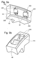
- the embodiment of the support element 36 according to FIG. 9a differs from FIG the one of Fig. 8a by the positioning of the circumferential stops 220 for the Roller arrangement 44 in the support element body 40.
- the circumferential stops 220 for the Roller arrangement 44 in the support element body 40 are in the Ab racelementen stresses 40 axially on both sides of the respective Auswölbevertiefung 214 provided for the rolling elements 42 circumferential stops 220, to which each support a receptacle 204 for an axle 46.
- the respective circumferential free end of each receptacle 204 effective as positioning 222, which cooperates with the corresponding circumferential stop 220.
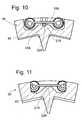
- Supporting member of FIG. 10 is the radial stop 218 by a in a Recess 225 in the bottom 226 of the Ab hydrolementen stressess 40 substantially centrally located and substantially axially extending pin 224 educated.
- the bolt 224 serves as a pivot line for the connecting part 200 and so that for the entire roller assembly 44. Because of this bolt 224 is at Force support between Ab monolementen endeavor 40 and spring element 90th occurring surface pressure controllable.
- a bolt 224 functionally corresponding bulge 228 in the bottom 226 of the Ab prolementen stresses 40 is effective as a radial stop 218.
- a pin 230 is provided whose radially inner part 231 has a larger diameter than its radially outer part 233, so that at the diameter transition a substantially annular support 235 is formed.
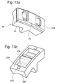
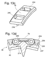
- the execution of the support member 36 of FIG. 13a corresponds to Substantially that of Fig. 8a, leaving as the only difference that in the support member 36 of FIG. 13a the support member body 40 is a radial outer cover 234 is assigned, at the radial outer side of the Sliding surface area 78 is formed.
- the cover 234 off be formed a material with particularly good sliding properties, or on be machined or coated according to its Gleit vom Scheme 78.
- the cover 234 is smaller in the circumferential direction than that Ab M Mg. 40 is smaller in the circumferential direction than that Ab Mg. 40 is smaller in the circumferential direction than that Ab Mg. 40 is smaller in the circumferential direction than that Ab Mg. 40 is smaller in the circumferential direction than that Ab Mg. 40 is smaller in the circumferential direction than that Ab Mg. 40 is smaller in the circumferential direction than that Ab Mg. 40 is smaller in the circumferential direction than that Ab polymeric material.
- the cover 234 is smaller in the circumferential direction than that Ab Mg. 1).
- the cover 234 takes over one Stop function in the circumferential direction to limit the compression travel of this point not shown damper elements 24 of the damper element assembly 26 (see Fig. 1).
- the Ab rangelementen stresses 40 can thereby a shock-resistant tough material, while the non-shock-loaded Cover 234 can be optimized substantially for good sliding properties.
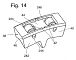
- FIG. 14 shows a support element 36, in which the support element body 40 abuts at least one axial outside 242 assembly openings 244 for the axes 46th the rolling elements 42 has.
- the support member 36 are the rolling elements 42 inserted from radially outward, while the axes 46 axially from the outside 242 inserted from and for the production of the roller assembly 44th be pressed into the receptacles 204 of the spring element 90.
- the mounting holes 244 are, at least one Extension component in the radial direction, extended to the axes 46 at Jamming of the rolling organs 42 does not hinder.
- the Form of the mounting holes 244 to the path of the axes 46 during compression of the Rolling organs 42 adapted.
- FIGS. 23 and 24 each show a support element 36 with fluid passages 255 shown, the latter for a flow of viscous medium provided and therefore in the radially outer extension region of the support element 36 are arranged, ie in that extension region in which In any case, centrifugal force accumulates viscous medium in the primary side 12.
- the fluid passages 255 are a groove on the radial outside provided the support member 36, as shown in FIG. 24, however, as Through openings on the peripheral sides of the support element.
- the respective fluid passage 255 acts as a fluid outlet for each with one of Fluid passages 255 in communicating Auswölbevertiefung 214 of Ab spacelementes 36.
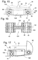
- FIG. 15 and 16 An alternative embodiment of a support element, in which the previously mentioned elasticity of the elastic assembly 68th is integrated, is shown in Figures 15 and 16.
- the support elements 36 are basically divided into two areas, namely the a the example again made of plastic Ab rangelementen stresses 40 on which also the damper elements 24 of the damper element assembly 26th are supported.
- a roller organ carrier 100 is provided on which now the For example, two rolling elements 42 of the roller assembly 44 of a respective Supporting element 36 are worn.
- each of the Rolling organs 42 again an axis 46, but now in its central area for example, via a sleeve-like carrier element formed from metal material 102 on the example made of plastic material rolling element carrier 100th for example, is not rotatably supported. Wearing on both side end areas Each axis 46 each have a rolling area 48, for example, again comprising a Bearing outer ring, which has a plurality of rolling elements either directly to the Axis 46 or carried on the axle 46 bearing inner ring is worn. Between the end regions of the roller organ carrier 100, in which the rolling elements 42 this support member 36 are supported, are two lateral recesses 104, 106 formed.
- the elastic assembly 68 for example in the form of two or more elastomer blocks 110 is formed. It should be noted here that, of course, other elastic elements, such as spring sheets, Helical compression springs or the like. can be used.
- This elastic Arrangement 68 now provides a restoring force, which basically the Centrifugal force F is opposite and ensures that at below a certain The centrifugal force lying centrifugal force of the sliding surface area 78 is not on the opposite Gleit vom Scheme 62 is present.
- a support member 36 is shown, which basically in its construction corresponds to the recognizable in Fig. 8 support element. While the support element 36 of FIG. 15 was designed to a peripheral support individual Damper elements 24 of a group of damper elements to each other realize, the support member 36 shown in FIG Circumferential direction last damper element 24 of such a group of Damper elements with respect to the primary side 12 and also the secondary side 30 support.
- the support projection 88 is configured with a contour which a uniform as possible burden of the same when acted upon by the Ensures primary side or secondary side.
- a wear protection layer be provided, or it may be a wear-resistant element, such as. a hardened sheet metal element may be provided there.
- a wear-resistant element such as. a hardened sheet metal element
- FIG. 1 Another support element 36 is shown in FIG.
- This support element 36 is trained, for example, with a longer circumferential extent designed damper elements 24 not at the end, but at one set between the end regions of the same lying intermediate area become.
- a clip portion 112 is on the Ab prolementen stresses 40 provided, which acts on the spring coils of a damper element as effective Clamping pressure spring can be clamped.
- the support member 40 is in this embodiment with a radially externally open recess 114 formed.
- the Roller assembly 44 here for example, a roller cage 116 with several Rolling organs 42 carried therein, for example rolling bearings, rollers, needles or the like. may include.
- This roller assembly 44 is in the recess 114 in FIG Circumferential direction, including the direction of movement of the support member 36, in limited range of movement movable and can thereby on an insert 118, for example, a metal part, unroll.
- the support portion 38 a from a metal part 120 or the like. have formed rolling surface area 56. This rolling surface area can again radially elastic using an indicated only by dashed line elastic Arrangement on the primary side 12 to be worn.
- Supporting element 36 further comprises a rolling carriage 122.
- the Abrollschlitten 122 is supported on the metal part 120, which in turn under Interposition of the elastic assembly 68, for example with respect to Primary side 12 is supported.
- a design variant is shown, in which the roller assembly 44 or the various rolling members 42 thereof not on the support elements 36, but on the support portion 38 of the primary side 12 are provided.
- the rolling elements 42 stand with their rolling area 48 in this case radially inward over a or a respective rolling element receiving Recess 150 out.
- the mutual circumferential distance of now the support area 38th provided rolling members 42 is such that the individual support members 36 themselves stable in its circumferential movement and without the risk of tilting radially can support outside.
- the arrangement is such that at least always two such rolling elements 42 a support for the supporting elements 36th can provide.
- the elastic assembly 68 is compressed, whereby the elements 154 dive deeper into the recess 152. In doing so, approach the sections 74, 76 the opposite sections 58, 60 at, until finally, once again reaching a certain speed or centrifugal force additional sliding support is generated.
- the elastic assembly 68 in a variety of May be configured and example, a Wellfederelement, an elastomer block, helical compression springs or the like. may include.
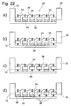
- the support takes place both with respect to the primary side 12 and the Secondary side 30 and with respect to circumferentially following Damper elements 24 designed with such rolling or rolling / sliding behavior Ab leveragelemente off.
- diagram b) are those supporting elements, which in Compression case, the support with respect to the primary side 12 and secondary side 30 realize not supported on roller assemblies, but are for example in a conventional manner only sliding relative to the support portion 38th supported. This leads to a defined permanently existing, of course, depending on centrifugal force also changing sliding friction damping in relative movement between primary side 12 and secondary side 30. Since the four However, inner support members 36 have the rolling behavior, all Damper elements 24 loaded in the same manner or at the same Embodiment of the same be compressed.
- the two are also in the middle positioned support members 36 only sliding relative to the support portion 38th supported, so that in circumferential movement between the primary side 12 and Secondary side 30 first reinforces the two in the circumferential ends of the Group of damper elements lying damper elements 24 are compressed and only then, if one the friction torque of the two centrally positioned Ab 100 peripheral force is built up, is also the center positioned damper element 24 are compressed.
- the arrangement is such that three each immediately adjacent support members 36 with rolling or rolling / sliding characteristic are configured while the other three support members 36 only one through have a sharp arrow each indexed sliding characteristic.
- damper elements 24 are first loaded or be compressed with the support elements with rolling characteristics interact, while in the other damper elements 24 first No or reduced compression will occur.
Landscapes
- Engineering & Computer Science (AREA)
- General Engineering & Computer Science (AREA)
- Physics & Mathematics (AREA)
- Acoustics & Sound (AREA)
- Aviation & Aerospace Engineering (AREA)
- Mechanical Engineering (AREA)
- Mechanical Operated Clutches (AREA)
- Surgical Instruments (AREA)
- Buildings Adapted To Withstand Abnormal External Influences (AREA)
- Support Of The Bearing (AREA)
- Rolling Contact Bearings (AREA)
Applications Claiming Priority (4)
| Application Number | Priority Date | Filing Date | Title |
|---|---|---|---|
| DE102004024740 | 2004-05-19 | ||
| DE102004024740 | 2004-05-19 | ||
| DE102004057352A DE102004057352A1 (de) | 2004-05-19 | 2004-11-27 | Torsionsschwingungsdämpfer |
| DE102004057352 | 2004-11-27 |
Publications (2)
| Publication Number | Publication Date |
|---|---|
| EP1598575A1 true EP1598575A1 (fr) | 2005-11-23 |
| EP1598575B1 EP1598575B1 (fr) | 2006-11-15 |
Family
ID=34936316
Family Applications (1)
| Application Number | Title | Priority Date | Filing Date |
|---|---|---|---|
| EP05010087A Expired - Lifetime EP1598575B1 (fr) | 2004-05-19 | 2005-05-10 | Amortisseur de vibrations en torsion |
Country Status (3)
| Country | Link |
|---|---|
| EP (1) | EP1598575B1 (fr) |
| AT (1) | ATE345456T1 (fr) |
| DE (2) | DE102004057352A1 (fr) |
Cited By (3)
| Publication number | Priority date | Publication date | Assignee | Title |
|---|---|---|---|---|
| EP2031272A3 (fr) * | 2007-08-27 | 2010-07-28 | LuK Lamellen und Kupplungsbau Beteiligungs KG | Amortisseur de vibrations de torsions |
| EP1662173B2 (fr) † | 2004-11-30 | 2011-10-26 | Schaeffler Technologies AG & Co. KG | Amortisseur d'oscillations de torsion |
| WO2018193397A1 (fr) | 2017-04-19 | 2018-10-25 | Concordia Textiles Nv | Produit textile insectifuge |
Families Citing this family (1)
| Publication number | Priority date | Publication date | Assignee | Title |
|---|---|---|---|---|
| DE102007016744A1 (de) | 2007-04-07 | 2008-10-09 | Zf Friedrichshafen Ag | Torsionsschwingungsdämpfer |
Citations (2)
| Publication number | Priority date | Publication date | Assignee | Title |
|---|---|---|---|---|
| DE19751029A1 (de) * | 1996-11-21 | 1998-05-28 | Valeo | Zweimassen-Dämpfungsschwungrad für Kraftfahrzeuge |
| DE10241879A1 (de) * | 2001-09-17 | 2003-04-10 | Luk Lamellen & Kupplungsbau | Drehschwingungsdämpfer |
-
2004
- 2004-11-27 DE DE102004057352A patent/DE102004057352A1/de not_active Withdrawn
-
2005
- 2005-05-10 DE DE502005000186T patent/DE502005000186D1/de not_active Expired - Lifetime
- 2005-05-10 AT AT05010087T patent/ATE345456T1/de not_active IP Right Cessation
- 2005-05-10 EP EP05010087A patent/EP1598575B1/fr not_active Expired - Lifetime
Patent Citations (2)
| Publication number | Priority date | Publication date | Assignee | Title |
|---|---|---|---|---|
| DE19751029A1 (de) * | 1996-11-21 | 1998-05-28 | Valeo | Zweimassen-Dämpfungsschwungrad für Kraftfahrzeuge |
| DE10241879A1 (de) * | 2001-09-17 | 2003-04-10 | Luk Lamellen & Kupplungsbau | Drehschwingungsdämpfer |
Cited By (3)
| Publication number | Priority date | Publication date | Assignee | Title |
|---|---|---|---|---|
| EP1662173B2 (fr) † | 2004-11-30 | 2011-10-26 | Schaeffler Technologies AG & Co. KG | Amortisseur d'oscillations de torsion |
| EP2031272A3 (fr) * | 2007-08-27 | 2010-07-28 | LuK Lamellen und Kupplungsbau Beteiligungs KG | Amortisseur de vibrations de torsions |
| WO2018193397A1 (fr) | 2017-04-19 | 2018-10-25 | Concordia Textiles Nv | Produit textile insectifuge |
Also Published As
| Publication number | Publication date |
|---|---|
| DE502005000186D1 (de) | 2006-12-28 |
| EP1598575B1 (fr) | 2006-11-15 |
| ATE345456T1 (de) | 2006-12-15 |
| DE102004057352A1 (de) | 2005-12-08 |
Similar Documents
| Publication | Publication Date | Title |
|---|---|---|
| DE69405215T2 (de) | Dämpfungseinrichtung zum ausgleichen von drehstössen und reibungskupplung mit einer derartigen vorrichtung | |
| DE102004062949B4 (de) | Torsionsschwingungsdämpfer | |
| DE102009010126A1 (de) | Drehschwingungsdämpfer | |
| DE3440927C2 (de) | Drehmomentübertragungseinrichtung | |
| DE10241879A1 (de) | Drehschwingungsdämpfer | |
| DE3875926T2 (de) | Schwungrad mit einem schwingungsdaempfer. | |
| DE102014117000A1 (de) | Pendeldämpfungsvorrichtung | |
| EP1272776B1 (fr) | Element ressort, notamment pour amortisseur d'oscillations de torsion | |
| DE102007016744A1 (de) | Torsionsschwingungsdämpfer | |
| DE19709343B4 (de) | Torsionsschwingungsdämpfer mit einer Reibvorrichtung | |
| DE102012218926A1 (de) | Drehschwingungsdämpfungsanordnung mit Vorspannung | |
| WO2009043325A1 (fr) | Amortisseur de vibrations de torsion | |
| EP1462675A2 (fr) | Amortisseur de vibrations de torsion | |
| DE19645174B4 (de) | Schwungmassenvorrichtung mit einer Gleitlagerung | |
| DE4203448A1 (de) | Riemenspannvorrichtung | |
| DE102008013577B4 (de) | Torsionsschwingungsdämpfer | |
| DE3545745C2 (de) | Torsionsschwingungsdämpfer mit verschleppter Reibung | |
| EP1598575B1 (fr) | Amortisseur de vibrations en torsion | |
| DE102011016995A1 (de) | Freilauf, insbesondere für ein Kurbel-CVT-Getriebe | |
| DE102011014337A1 (de) | Kupplungsbaugruppe einer Kraftfahrzeugkupplung mit einem Drehmomentbegrenzer | |
| DE19819824B4 (de) | Torsionsschwingungsdämpfer mit einer Dämpfungseinrichtung | |
| DE19620698A1 (de) | Schwungmassenvorrichtung mit einer Gleitlagerung | |
| DE10013857B4 (de) | Doppelkupplung | |
| EP2598774A1 (fr) | Amortisseur d'oscillations de torsion | |
| DE19958814A1 (de) | Drehschwingungsdämpfer |
Legal Events
| Date | Code | Title | Description |
|---|---|---|---|
| PUAI | Public reference made under article 153(3) epc to a published international application that has entered the european phase |
Free format text: ORIGINAL CODE: 0009012 |
|
| 17P | Request for examination filed |
Effective date: 20050809 |
|
| AK | Designated contracting states |
Kind code of ref document: A1 Designated state(s): AT BE BG CH CY CZ DE DK EE ES FI FR GB GR HU IE IS IT LI LT LU MC NL PL PT RO SE SI SK TR |
|
| AX | Request for extension of the european patent |
Extension state: AL BA HR LV MK YU |
|
| GRAP | Despatch of communication of intention to grant a patent |
Free format text: ORIGINAL CODE: EPIDOSNIGR1 |
|
| GRAS | Grant fee paid |
Free format text: ORIGINAL CODE: EPIDOSNIGR3 |
|
| AKX | Designation fees paid |
Designated state(s): AT BE BG CH CY CZ DE DK EE ES FI FR GB GR HU IE IS IT LI LT LU MC NL PL PT RO SE SI SK TR |
|
| GRAA | (expected) grant |
Free format text: ORIGINAL CODE: 0009210 |
|
| AK | Designated contracting states |
Kind code of ref document: B1 Designated state(s): AT BE BG CH CY CZ DE DK EE ES FI FR GB GR HU IE IS IT LI LT LU MC NL PL PT RO SE SI SK TR |
|
| PG25 | Lapsed in a contracting state [announced via postgrant information from national office to epo] |
Ref country code: IT Free format text: LAPSE BECAUSE OF FAILURE TO SUBMIT A TRANSLATION OF THE DESCRIPTION OR TO PAY THE FEE WITHIN THE PRESCRIBED TIME-LIMIT;WARNING: LAPSES OF ITALIAN PATENTS WITH EFFECTIVE DATE BEFORE 2007 MAY HAVE OCCURRED AT ANY TIME BEFORE 2007. THE CORRECT EFFECTIVE DATE MAY BE DIFFERENT FROM THE ONE RECORDED. Effective date: 20061115 Ref country code: RO Free format text: LAPSE BECAUSE OF FAILURE TO SUBMIT A TRANSLATION OF THE DESCRIPTION OR TO PAY THE FEE WITHIN THE PRESCRIBED TIME-LIMIT Effective date: 20061115 Ref country code: NL Free format text: LAPSE BECAUSE OF FAILURE TO SUBMIT A TRANSLATION OF THE DESCRIPTION OR TO PAY THE FEE WITHIN THE PRESCRIBED TIME-LIMIT Effective date: 20061115 Ref country code: LT Free format text: LAPSE BECAUSE OF FAILURE TO SUBMIT A TRANSLATION OF THE DESCRIPTION OR TO PAY THE FEE WITHIN THE PRESCRIBED TIME-LIMIT Effective date: 20061115 Ref country code: CZ Free format text: LAPSE BECAUSE OF FAILURE TO SUBMIT A TRANSLATION OF THE DESCRIPTION OR TO PAY THE FEE WITHIN THE PRESCRIBED TIME-LIMIT Effective date: 20061115 Ref country code: SK Free format text: LAPSE BECAUSE OF FAILURE TO SUBMIT A TRANSLATION OF THE DESCRIPTION OR TO PAY THE FEE WITHIN THE PRESCRIBED TIME-LIMIT Effective date: 20061115 Ref country code: PL Free format text: LAPSE BECAUSE OF FAILURE TO SUBMIT A TRANSLATION OF THE DESCRIPTION OR TO PAY THE FEE WITHIN THE PRESCRIBED TIME-LIMIT Effective date: 20061115 Ref country code: FI Free format text: LAPSE BECAUSE OF FAILURE TO SUBMIT A TRANSLATION OF THE DESCRIPTION OR TO PAY THE FEE WITHIN THE PRESCRIBED TIME-LIMIT Effective date: 20061115 Ref country code: SI Free format text: LAPSE BECAUSE OF FAILURE TO SUBMIT A TRANSLATION OF THE DESCRIPTION OR TO PAY THE FEE WITHIN THE PRESCRIBED TIME-LIMIT Effective date: 20061115 Ref country code: IE Free format text: LAPSE BECAUSE OF FAILURE TO SUBMIT A TRANSLATION OF THE DESCRIPTION OR TO PAY THE FEE WITHIN THE PRESCRIBED TIME-LIMIT Effective date: 20061115 |
|
| REG | Reference to a national code |
Ref country code: GB Ref legal event code: FG4D Free format text: NOT ENGLISH |
|
| REG | Reference to a national code |
Ref country code: CH Ref legal event code: EP |
|
| REF | Corresponds to: |
Ref document number: 502005000186 Country of ref document: DE Date of ref document: 20061228 Kind code of ref document: P |
|
| REG | Reference to a national code |
Ref country code: IE Ref legal event code: FG4D Free format text: LANGUAGE OF EP DOCUMENT: GERMAN |
|
| PG25 | Lapsed in a contracting state [announced via postgrant information from national office to epo] |
Ref country code: SE Free format text: LAPSE BECAUSE OF FAILURE TO SUBMIT A TRANSLATION OF THE DESCRIPTION OR TO PAY THE FEE WITHIN THE PRESCRIBED TIME-LIMIT Effective date: 20070215 Ref country code: DK Free format text: LAPSE BECAUSE OF FAILURE TO SUBMIT A TRANSLATION OF THE DESCRIPTION OR TO PAY THE FEE WITHIN THE PRESCRIBED TIME-LIMIT Effective date: 20070215 Ref country code: BG Free format text: LAPSE BECAUSE OF FAILURE TO SUBMIT A TRANSLATION OF THE DESCRIPTION OR TO PAY THE FEE WITHIN THE PRESCRIBED TIME-LIMIT Effective date: 20070215 |
|
| PG25 | Lapsed in a contracting state [announced via postgrant information from national office to epo] |
Ref country code: ES Free format text: LAPSE BECAUSE OF FAILURE TO SUBMIT A TRANSLATION OF THE DESCRIPTION OR TO PAY THE FEE WITHIN THE PRESCRIBED TIME-LIMIT Effective date: 20070226 |
|
| GBT | Gb: translation of ep patent filed (gb section 77(6)(a)/1977) |
Effective date: 20070213 |
|
| PG25 | Lapsed in a contracting state [announced via postgrant information from national office to epo] |
Ref country code: IS Free format text: LAPSE BECAUSE OF FAILURE TO SUBMIT A TRANSLATION OF THE DESCRIPTION OR TO PAY THE FEE WITHIN THE PRESCRIBED TIME-LIMIT Effective date: 20070315 |
|
| PG25 | Lapsed in a contracting state [announced via postgrant information from national office to epo] |
Ref country code: PT Free format text: LAPSE BECAUSE OF FAILURE TO SUBMIT A TRANSLATION OF THE DESCRIPTION OR TO PAY THE FEE WITHIN THE PRESCRIBED TIME-LIMIT Effective date: 20070416 |
|
| NLV1 | Nl: lapsed or annulled due to failure to fulfill the requirements of art. 29p and 29m of the patents act | ||
| ET | Fr: translation filed | ||
| REG | Reference to a national code |
Ref country code: IE Ref legal event code: FD4D |
|
| PLBE | No opposition filed within time limit |
Free format text: ORIGINAL CODE: 0009261 |
|
| STAA | Information on the status of an ep patent application or granted ep patent |
Free format text: STATUS: NO OPPOSITION FILED WITHIN TIME LIMIT |
|
| 26N | No opposition filed |
Effective date: 20070817 |
|
| BERE | Be: lapsed |
Owner name: ZF FRIEDRICHSHAFEN A.G. Effective date: 20070531 |
|
| PG25 | Lapsed in a contracting state [announced via postgrant information from national office to epo] |
Ref country code: MC Free format text: LAPSE BECAUSE OF NON-PAYMENT OF DUE FEES Effective date: 20070531 |
|
| PG25 | Lapsed in a contracting state [announced via postgrant information from national office to epo] |
Ref country code: BE Free format text: LAPSE BECAUSE OF NON-PAYMENT OF DUE FEES Effective date: 20070531 |
|
| PG25 | Lapsed in a contracting state [announced via postgrant information from national office to epo] |
Ref country code: GR Free format text: LAPSE BECAUSE OF FAILURE TO SUBMIT A TRANSLATION OF THE DESCRIPTION OR TO PAY THE FEE WITHIN THE PRESCRIBED TIME-LIMIT Effective date: 20070216 |
|
| PG25 | Lapsed in a contracting state [announced via postgrant information from national office to epo] |
Ref country code: AT Free format text: LAPSE BECAUSE OF NON-PAYMENT OF DUE FEES Effective date: 20070510 |
|
| PG25 | Lapsed in a contracting state [announced via postgrant information from national office to epo] |
Ref country code: EE Free format text: LAPSE BECAUSE OF FAILURE TO SUBMIT A TRANSLATION OF THE DESCRIPTION OR TO PAY THE FEE WITHIN THE PRESCRIBED TIME-LIMIT Effective date: 20061115 |
|
| PG25 | Lapsed in a contracting state [announced via postgrant information from national office to epo] |
Ref country code: LU Free format text: LAPSE BECAUSE OF NON-PAYMENT OF DUE FEES Effective date: 20070510 Ref country code: CY Free format text: LAPSE BECAUSE OF FAILURE TO SUBMIT A TRANSLATION OF THE DESCRIPTION OR TO PAY THE FEE WITHIN THE PRESCRIBED TIME-LIMIT Effective date: 20061115 |
|
| PGFP | Annual fee paid to national office [announced via postgrant information from national office to epo] |
Ref country code: FR Payment date: 20090515 Year of fee payment: 5 |
|
| PG25 | Lapsed in a contracting state [announced via postgrant information from national office to epo] |
Ref country code: TR Free format text: LAPSE BECAUSE OF FAILURE TO SUBMIT A TRANSLATION OF THE DESCRIPTION OR TO PAY THE FEE WITHIN THE PRESCRIBED TIME-LIMIT Effective date: 20061115 Ref country code: HU Free format text: LAPSE BECAUSE OF FAILURE TO SUBMIT A TRANSLATION OF THE DESCRIPTION OR TO PAY THE FEE WITHIN THE PRESCRIBED TIME-LIMIT Effective date: 20070516 |
|
| PGFP | Annual fee paid to national office [announced via postgrant information from national office to epo] |
Ref country code: GB Payment date: 20090506 Year of fee payment: 5 |
|
| REG | Reference to a national code |
Ref country code: CH Ref legal event code: PL |
|
| PG25 | Lapsed in a contracting state [announced via postgrant information from national office to epo] |
Ref country code: CH Free format text: LAPSE BECAUSE OF NON-PAYMENT OF DUE FEES Effective date: 20090531 Ref country code: LI Free format text: LAPSE BECAUSE OF NON-PAYMENT OF DUE FEES Effective date: 20090531 |
|
| GBPC | Gb: european patent ceased through non-payment of renewal fee |
Effective date: 20100510 |
|
| REG | Reference to a national code |
Ref country code: FR Ref legal event code: ST Effective date: 20110131 |
|
| PG25 | Lapsed in a contracting state [announced via postgrant information from national office to epo] |
Ref country code: FR Free format text: LAPSE BECAUSE OF NON-PAYMENT OF DUE FEES Effective date: 20100531 |
|
| PG25 | Lapsed in a contracting state [announced via postgrant information from national office to epo] |
Ref country code: GB Free format text: LAPSE BECAUSE OF NON-PAYMENT OF DUE FEES Effective date: 20100510 |
|
| PGFP | Annual fee paid to national office [announced via postgrant information from national office to epo] |
Ref country code: DE Payment date: 20150506 Year of fee payment: 11 |
|
| REG | Reference to a national code |
Ref country code: DE Ref legal event code: R119 Ref document number: 502005000186 Country of ref document: DE |
|
| PG25 | Lapsed in a contracting state [announced via postgrant information from national office to epo] |
Ref country code: DE Free format text: LAPSE BECAUSE OF NON-PAYMENT OF DUE FEES Effective date: 20161201 |