EP1598582B1 - Entretoise modulaire pour tuyaux concentriques - Google Patents
Entretoise modulaire pour tuyaux concentriques Download PDFInfo
- Publication number
- EP1598582B1 EP1598582B1 EP20040425363 EP04425363A EP1598582B1 EP 1598582 B1 EP1598582 B1 EP 1598582B1 EP 20040425363 EP20040425363 EP 20040425363 EP 04425363 A EP04425363 A EP 04425363A EP 1598582 B1 EP1598582 B1 EP 1598582B1
- Authority
- EP
- European Patent Office
- Prior art keywords
- adapter
- pipe
- spacer
- spacing
- ridge
- Prior art date
- Legal status (The legal status is an assumption and is not a legal conclusion. Google has not performed a legal analysis and makes no representation as to the accuracy of the status listed.)
- Expired - Lifetime
Links
- 125000006850 spacer group Chemical group 0.000 title claims description 17
- 230000008878 coupling Effects 0.000 claims description 4
- 238000010168 coupling process Methods 0.000 claims description 4
- 238000005859 coupling reaction Methods 0.000 claims description 4
- 230000002093 peripheral effect Effects 0.000 claims description 3
- 238000004026 adhesive bonding Methods 0.000 claims 1
- 238000007789 sealing Methods 0.000 claims 1
- 239000000463 material Substances 0.000 description 9
- 239000004698 Polyethylene Substances 0.000 description 5
- 229920000573 polyethylene Polymers 0.000 description 5
- XLYOFNOQVPJJNP-UHFFFAOYSA-N water Substances O XLYOFNOQVPJJNP-UHFFFAOYSA-N 0.000 description 5
- 239000004033 plastic Substances 0.000 description 4
- 229920003023 plastic Polymers 0.000 description 4
- -1 polyethylene Polymers 0.000 description 3
- 229910000831 Steel Inorganic materials 0.000 description 2
- 230000006835 compression Effects 0.000 description 2
- 238000007906 compression Methods 0.000 description 2
- 230000037431 insertion Effects 0.000 description 2
- 238000003780 insertion Methods 0.000 description 2
- 239000011810 insulating material Substances 0.000 description 2
- 238000009413 insulation Methods 0.000 description 2
- 238000003754 machining Methods 0.000 description 2
- 239000002184 metal Substances 0.000 description 2
- 238000000465 moulding Methods 0.000 description 2
- 229920003229 poly(methyl methacrylate) Polymers 0.000 description 2
- 239000004926 polymethyl methacrylate Substances 0.000 description 2
- 239000010959 steel Substances 0.000 description 2
- OKTJSMMVPCPJKN-UHFFFAOYSA-N Carbon Chemical compound [C] OKTJSMMVPCPJKN-UHFFFAOYSA-N 0.000 description 1
- 239000004952 Polyamide Substances 0.000 description 1
- 239000004809 Teflon Substances 0.000 description 1
- 229920006362 Teflon® Polymers 0.000 description 1
- 238000005299 abrasion Methods 0.000 description 1
- 239000000853 adhesive Substances 0.000 description 1
- 230000001070 adhesive effect Effects 0.000 description 1
- 238000005452 bending Methods 0.000 description 1
- 230000005540 biological transmission Effects 0.000 description 1
- 229910052799 carbon Inorganic materials 0.000 description 1
- 239000000919 ceramic Substances 0.000 description 1
- 239000004020 conductor Substances 0.000 description 1
- 230000007797 corrosion Effects 0.000 description 1
- 238000005260 corrosion Methods 0.000 description 1
- 230000006866 deterioration Effects 0.000 description 1
- 239000000835 fiber Substances 0.000 description 1
- 238000007667 floating Methods 0.000 description 1
- 239000003365 glass fiber Substances 0.000 description 1
- 239000003292 glue Substances 0.000 description 1
- 238000001746 injection moulding Methods 0.000 description 1
- 229920002647 polyamide Polymers 0.000 description 1
- 230000000750 progressive effect Effects 0.000 description 1
- 230000002787 reinforcement Effects 0.000 description 1
Images



Classifications
-
- F—MECHANICAL ENGINEERING; LIGHTING; HEATING; WEAPONS; BLASTING
- F16—ENGINEERING ELEMENTS AND UNITS; GENERAL MEASURES FOR PRODUCING AND MAINTAINING EFFECTIVE FUNCTIONING OF MACHINES OR INSTALLATIONS; THERMAL INSULATION IN GENERAL
- F16L—PIPES; JOINTS OR FITTINGS FOR PIPES; SUPPORTS FOR PIPES, CABLES OR PROTECTIVE TUBING; MEANS FOR THERMAL INSULATION IN GENERAL
- F16L7/00—Supporting pipes or cables inside other pipes or sleeves, e.g. for enabling pipes or cables to be inserted or withdrawn from under roads or railways without interruption of traffic
Definitions
- the invention relates to the field of the spacing collars for pipes.
- spacing collars are attached, spaced axially, on a portion of internal pipe and said pipe, supported by the spacing collar, is made to slide inside the external pipe, or shell pipe, to the position required.
- the spacing collar thus also is an assembly means and it is important that it allows excellent sliding without friction.
- a spacing collar generally comprises one or more elements formed by a base band or plate, designed to be bent around the internal pipe, whereon a plurality of ridges are formed in a single piece and arranged radially in relation to the internal pipe. The ends of the ridges touch the external pipe, keeping it distanced from the internal one.
- the collar In the case wherein large distances are required between the pipes, the collar must have very high radial ridges. In this case there are constructional restrictions of moulding or machining for obtaining collars with very high ridges. Moreover, a collar with high ridges will occupy a very large volume, with consequent problems of bulk, storage and transport.
- known spacing collars are made in a plastic material such as polyethylene, which is sufficiently elastic to be bent around the internal pipe. This material is inadequate when the ridges of the collars -working with very heavy pipes - are subjected to high pressures or when they are subjected to high friction, having to slide for a long length within the pipe, particularly within a pipe with a high degree of roughness (for example a concrete pipes).
- the adapted is rectangular in shape, comprises an upper part smaller in size and is provided with ribs and with at least a siege suitable to receive fixing means inserted in a hole provided in a ridge of the spacing element.
- Object of the present invention is to overcome the drawbacks of the prior art by providing an adapter element which is versatile and suitable for attachment to various types of spacing collars for pipes so as to adapt the collar to various application possibilities.
- Another object of the present invention is to provide an adapter element, which is strong and reliable, which can be produced at low costs and fitted easily and which can be composed of a single element or of several modular elements.
- the adapter according to the invention is attached to a spacer for pipes such as gas pipelines, oil pipelines and the like.
- the spacer comprises at least one spacing element comprising a base band which can be attached to the external surface of an internal pipe and a plurality of ridges projecting from the base band in such a way that their ends come into contact with the internal surface of an external pipe to maintain it separate from said internal pipe.
- the adapter can be coupled to said ridge so as to prolong its height in accordance with the difference in diameter between said internal pipe and said external pipe
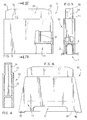
- Figs. 1 and 2 show a first known spacing element 1, such as that described in the European patent EP 1 262 700 in the name of the same Applicant.
- the spacing element 1 comprises a base band 2, substantially flat in the absence of applied forces and flexible.
- Slide spacing ridges 3 project upwards from one face of the band 2.
- the spacing ridges 3 can have any shape known in the field and preferably they have a shape with a rounded section and with an elongated plan and can be configured with various heights in relation to the plane of the base band, according to the radial distance to be maintained between the internal pipe and the external pipe.
- Toothed coupling tabs 4 extend from one side of the band 2. Starting from the end opposite to the tabs 4, the ridges 3 have at the respective bases (Fig. 2) aligned openings 5 which overall form a housing for a tab 4. Some ridges 3 have guide fins or strips 6, which guide the insertion of the tabs 4 in the openings 5. The furthest end ridge from the tabs 4 has toothed retaining fins 7, which engage, with the teeth of the tabs 4. The guide strips 6 and the retaining fins 7 extend above the openings 5.
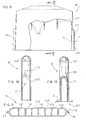
- the adapter element 10 has a substantially flattened parallelepiped shape and is open at the bottom to define a seat 11 having dimensions such as to accommodate a ridge 3 of the spacer 1 as shown in Fig. 5.
- the coupling between the adapter element 10 and the ridge 3 of the spacer can be pressure-forced, simply slotted, snap-slotted and the like.
- adhesive means such as glue or mechanical means such as rivets, nails, bolts and the like passing through the adapter 10 and the ridge 3 can be used.
- the mechanical means are preferably in a non-conducting material, such as plastic. In the case wherein both the adapter 10 and the ridge 3 are made in a heat-sealable plastic material, they can be heat-sealed one to the other as a further attachment system.
- the adapter element 10 can be of any height, for example a height that can vary from twice to 10 times the height of the ridge 3 whereon it is coupled.
- the body of the adapter 10 can be hollow internally, with possible reinforcement ribs 12 and 13.
- the adapter element 10 can be made in a plastic material through injection moulding.
- the same material as that of the spacing collar 1 can be used, such as for example PE (polyethylene).
- the adapter element 10 can be made in a material different from that of the spacing element which has to fulfil certain requirements of flexibility.
- the adapter element 10 can be made in polyamide (nylonTM) filled with glass fibre, in carbon fibre, in ceramic or in polymethylmethacrylate (PMMA).
- the adapter element 10 In the case wherein the adapter element 10 is to be subjected to high compression and bending loads, it can be made in the form of an insert or core in steel covered with an insulating material, such as polyethylene (PE) which guarantees insulation of the steel core.
- PE polyethylene
- the tip or the entire adapter element 10 can be covered with a self-lubricating material with a low friction coefficient such as Teflon.
- the upper part 14 of the adapter element 10 is preferably smaller in size when compared to the central part so as to define a peripheral abutment edge 15. In this way the upper part 14 of an adapter element 10 can be inserted in the base housing 11 of another adapter element, thus allowing a modular build-up in height of several adapter elements 10 so as to achieve the height required.
- the corners 16 of the upper part of the adapter are bevelled to overcome obstacles such as surface unevenness in concrete pipes or welds in metal pipes. The bevelled corners 16 also facilitate insertion of another adapter in the seat 11.
- the adapter element 10 In order to attach the adapter element 10 also to the ridges 3 wherein the openings 5, the guide strips 6 and the retaining tabs 7 are present, a variant has been conceived as shown in Fig. 6.
- the adapter element 10 has, in its lower part, a through slot 17 which is placed in register with the openings 5 for the passage of the tabs 4 of the spacing element.
- the guide strips 6 and the retaining tabs 7 can also pass through the slot 17.
- the adapter element 10 may have a substantially trapezoidal shape with a larger base 18 which has two sections 19 which extend outside of the band 2 of the spacing element 1.
- Figs. 7 and 8 show a known spacing element 101, such that described in Italian patent IT 1 301 565 in the name of the same Applicant.
- the spacing element 101 differs from the spacing element 1 described previously in that it provides engaging means in the form of slides 104 opposingly slanted and provided with retaining means 105 and 106.
- a joining and locking element (not shown in the figures) is provided, having slanted engaging parts with which it engages and locks the engaging means of the same spacing element closed in a loop, or two adjacent spacing elements.
- each ridge 3 has at its opposite ends two ribs 103 which extend until the ends of the base band 2.
- the adapter element 10 shown in Figs. 9-12, to adapt to the ridges 3 of the spacer 101 has two side ribs 111 which define internally respective seats 112 wherein the side ribs 103 of the ridges 3 can be housed.
- the seat 11 for housing the ridge 3 is defined by a plurality of internal transverse ribs 113 which have below a substantially curved profile 113' like the upper part of the ridges 3.
- transverse ribs 114 are provided, alternating with the long ribs 113.
- Fig. 13 shows a spacing collar formed by spacing elements 101 attached to an internal pipe 200.
- Adapter elements 10 of different length are mounted on the ridges 3 of the spacing elements 101. More specifically shorter adapter elements 10 are mounted on the ridges 3, which project upwards, and longer adapter elements 10 are mounted on the ridges 3 which project downwards.
- the internal pipe 200 when the internal pipe 200, with the spacing collar and the adapter elements 10, is inserted in an external pipe 201, the internal pipe 200 will be arranged eccentrically in relation to the external pipe 201 and its axis A will be higher than the axis B of the external pipe 201. Therefore the lower surface of the internal pipe 200 is at a level higher than its level if the internal pipe 200 were coaxial with the external pipe 201. Consequently, if there is seepage of water in the external pipe, the water level 203 which accumulates at the bottom of the external pipe 201 does not come into contact with the lower part of the internal pipe 200.
- joining elements 50 are provided in the form of rigid strips or cables, which are slotted or restrained laterally or at the head between two or more adjacent adapter elements 10.
- a service pipe 206 has to pass, holding - for example - a plurality of electrical cables 204.
- the service pipe 206 is surrounded by its spacing collar 1 so as to be distanced from its external pipe 205. In this case it is sufficient merely to remove a row of aligned adapter elements 10 in order to create a space for the passage of the service pipe 206 surrounded by its spacing collar 1 and by its external pipe 205.
Landscapes
- Engineering & Computer Science (AREA)
- General Engineering & Computer Science (AREA)
- Mechanical Engineering (AREA)
- Supports For Pipes And Cables (AREA)
Claims (10)
- Adaptateur (10) pour entretoise pour tuyaux comme des pipelines de gaz, des pipelines de pétrole et des éléments similaires, l'entretoise comprenant au moins un élément d'espacement (1 ; 101) comprenant une bande de base (2) qui peut être attachée à la surface externe d'un tuyau interne (200) et une pluralité d'arêtes (3) se projetant de ladite bande de base (2) de manière à ce que leurs extrémités entrent en contact avec la surface interne d'un tuyau externe (201) pour le maintenir séparé du tuyau interne (200), ledit adaptateur (10) comprenant un logement de base (11) conçu pour contenir l'une desdites arêtes (3) pour être apte à être couplé à ladite arête (3) pour étendre sa hauteur en fonction de la différence des valeurs de diamètre entre ledit tuyau interne (200) et ledit tuyau externe (201),
caractérisé en ce que la partie supérieure (14) de l'adaptateur (10) définit un bord d'aboutement périphérique (15) de manière à ce qu'un premier dudit adaptateur (10) puisse être inséré dans le logement de base (11) d'un second dudit adaptateur (10), ledit bord d'aboutement périphérique (15) fournissant un support pour ledit second dudit adaptateur (10) et permettant ainsi une accumulation modulaire en hauteur de plusieurs adaptateurs (10). - Adaptateur (10) selon la revendication 1, caractérisé en ce qu'il est couplé à ladite arête (3) en le forçant par pression, en l'insérant dans une fente ou en le couplant par enfoncement.
- Adaptateur (10) selon l'une quelconque des revendications précédentes, caractérisé en ce qu'il est attaché à ladite arête (3) et/ou à ladite bande de base (2) en le collant ou en le faisant adhérer thermiquement.
- Adaptateur (10) selon l'une quelconque des revendications précédentes, caractérisé en ce qu'il comprend une fente traversante (17) dans sa portion inférieure de manière à permettre le passage des attaches de fixation (4) pour la composition de plusieurs éléments d'espacement (1).
- Adaptateur (10) selon l'une quelconque des revendications précédentes, caractérisé en ce qu'il a une forme sensiblement trapézoïdale avec une base (18) qui est plus grande que la largeur de ladite bande de base (2) de l'élément d'espacement (1) de manière à avoir deux sections d'extrémité (19) qui se projettent à l'extérieur de ladite bande de base (2) de l'élément d'espacement (1).
- Adaptateur (10) selon l'une quelconque des revendications précédentes, caractérisé en ce qu'il comprend deux nervures latérales (111) qui définissent deux sièges latéraux (112) conçus pour contenir des nervures latérales respectives (103) fournies dans ladite arête (3) de l'élément d'espacement (101).
- Entretoise (1; 101) pour des tuyaux comme des pipelines de gaz, des pipelines de pétrole et des éléments similaires, caractérisée en ce qu'elle comprend des éléments adaptateurs (10) selon l'une quelconque des revendications précédentes.
- Entretoise (1; 101) selon la revendication 7, caractérisée en ce qu'elle comprend des éléments adaptateurs de longueurs différentes, de manière à permettre un assemblage excentrique du tuyau interne (200) par rapport au tuyau externe (201) ou un assemblage calibré avec plusieurs points de contact avec le tuyau externe (201) pour une répartition améliorée de la charge sur le collier d'espacement.
- Entretoise (1; 101) selon la revendication 7 ou 8, caractérisée en ce qu'elle comprend au moins un tuyau de service (203) qui passe dans la cavité entre le tuyau interne (200) et le tuyau externe (201) dans une portion dans laquelle il n'y a pas d'élément adaptateur (10).
- Entretoise (1; 101) selon l'une quelconque des revendications 7 à 9, caractérisée en ce qu'elle comprend au moins un élément de jonction (50) sous la forme d'une bande rigide ou d'un câble qui est inséré ou restreint latéralement ou à la tête entre deux ou plus d'éléments adaptateurs adjacents (10).
Priority Applications (3)
| Application Number | Priority Date | Filing Date | Title |
|---|---|---|---|
| ES04425363T ES2295809T3 (es) | 2004-05-19 | 2004-05-19 | Adaptador para distanciador para conductos como gaseoductos, oleoductos y similares. |
| EP20040425363 EP1598582B1 (fr) | 2004-05-19 | 2004-05-19 | Entretoise modulaire pour tuyaux concentriques |
| DE200460009762 DE602004009762T2 (de) | 2004-05-19 | 2004-05-19 | Modularer Distanzhalter für hindurchgeführte Rohre |
Applications Claiming Priority (1)
| Application Number | Priority Date | Filing Date | Title |
|---|---|---|---|
| EP20040425363 EP1598582B1 (fr) | 2004-05-19 | 2004-05-19 | Entretoise modulaire pour tuyaux concentriques |
Publications (2)
| Publication Number | Publication Date |
|---|---|
| EP1598582A1 EP1598582A1 (fr) | 2005-11-23 |
| EP1598582B1 true EP1598582B1 (fr) | 2007-10-31 |
Family
ID=34932506
Family Applications (1)
| Application Number | Title | Priority Date | Filing Date |
|---|---|---|---|
| EP20040425363 Expired - Lifetime EP1598582B1 (fr) | 2004-05-19 | 2004-05-19 | Entretoise modulaire pour tuyaux concentriques |
Country Status (3)
| Country | Link |
|---|---|
| EP (1) | EP1598582B1 (fr) |
| DE (1) | DE602004009762T2 (fr) |
| ES (1) | ES2295809T3 (fr) |
Families Citing this family (3)
| Publication number | Priority date | Publication date | Assignee | Title |
|---|---|---|---|---|
| DE602005023180D1 (de) * | 2005-11-08 | 2010-10-07 | Raci Srl | Verfahren zum Verstellen einer Abstandschelle für Rohre und Anordnung zum Positienieren eines Rohres |
| GB0523599D0 (en) * | 2005-11-19 | 2005-12-28 | Nylacast Ltd | Improved spacer |
| ITMI20061681A1 (it) * | 2006-09-04 | 2008-03-05 | Stampa Tecnica Articoli Materiali Plastici | Blocchetto di rinforzo delle alette cave di un distanziatore per tubi per il trasporto di fluidi |
Family Cites Families (3)
| Publication number | Priority date | Publication date | Assignee | Title |
|---|---|---|---|---|
| GB1332676A (en) * | 1971-07-26 | 1973-10-03 | Metal Pipeline Endurance Ltd | Electric insulating rings for spacing two concentric metal pipes apart |
| DE9114077U1 (de) * | 1991-11-11 | 1992-01-02 | MAGE-DSI GmbH Werke für Kunststoff- und Metallverarbeitung, 7401 Nehren | Distanzhalter für durch Schutzrohre hindurchgeführte Rohre |
| US5441082A (en) * | 1994-08-30 | 1995-08-15 | Cascade Waterworks Manufacturing Co. | Casing spacer |
-
2004
- 2004-05-19 DE DE200460009762 patent/DE602004009762T2/de not_active Expired - Lifetime
- 2004-05-19 EP EP20040425363 patent/EP1598582B1/fr not_active Expired - Lifetime
- 2004-05-19 ES ES04425363T patent/ES2295809T3/es not_active Expired - Lifetime
Also Published As
| Publication number | Publication date |
|---|---|
| DE602004009762T2 (de) | 2008-08-28 |
| EP1598582A1 (fr) | 2005-11-23 |
| DE602004009762D1 (de) | 2007-12-13 |
| ES2295809T3 (es) | 2008-04-16 |
Similar Documents
| Publication | Publication Date | Title |
|---|---|---|
| AU779134B2 (en) | Four piece cable tie | |
| US8398033B2 (en) | Cable clamp | |
| US4977931A (en) | Method of producing reinforced ribbed tubes | |
| US20110290523A1 (en) | Raceway for instrumentation lines | |
| US20060273226A1 (en) | Attachment device for a line | |
| US20120312253A1 (en) | Coil support member | |
| CA2725060C (fr) | Raccord de tuyau | |
| US20180109091A1 (en) | Energy chain comprising a holder for an external cable, receiving element and corresponding side plate | |
| US5209524A (en) | Pipe restraining collar member having protrusions of different sizes | |
| EP1598582A1 (fr) | Entretoise modulaire pour tuyaux concentriques | |
| KR101829819B1 (ko) | 파형강판 터널 | |
| US12060715B2 (en) | Support block assembly | |
| US9748755B1 (en) | Clip-based non-metallic fittings for attachment of flexible metallic conduit | |
| KR20090056636A (ko) | 케이블트레이 고정장치 | |
| KR19980015175U (ko) | 건물내 케이블 배설용 트레이 | |
| KR100858686B1 (ko) | 체결구를 구비한 합성수지 연결관 | |
| KR20090114537A (ko) | 수로관의 연결구조 | |
| JP4593583B2 (ja) | トラフ構造体及びその敷設方法 | |
| KR20090114536A (ko) | 흙을 이용한 수로관 | |
| EP1262700B1 (fr) | Elément distanceur pour des pipelines de gaz ou de pétrole et des tuyaux similaires | |
| EP1783412B1 (fr) | Méthode de réglage d'un collier d'entretoisement pour tuyaux et système de positionnement d'un tuyau | |
| JP2002213647A (ja) | 垂直方向の配管敷設工法 | |
| KR100515494B1 (ko) | 하수도관 연결구 | |
| JP2002165322A (ja) | 小型ダクトスリーブ | |
| KR100427209B1 (ko) | 플랜지 구조를 보강한 플랜지관과 플랜지관의 연결에사용되는 고무패킹 및 이를 이용한 관체 연결구 조립체 |
Legal Events
| Date | Code | Title | Description |
|---|---|---|---|
| PUAI | Public reference made under article 153(3) epc to a published international application that has entered the european phase |
Free format text: ORIGINAL CODE: 0009012 |
|
| AK | Designated contracting states |
Kind code of ref document: A1 Designated state(s): AT BE BG CH CY CZ DE DK EE ES FI FR GB GR HU IE IT LI LU MC NL PL PT RO SE SI SK TR |
|
| AX | Request for extension of the european patent |
Extension state: AL HR LT LV MK |
|
| 17P | Request for examination filed |
Effective date: 20060421 |
|
| 17Q | First examination report despatched |
Effective date: 20060622 |
|
| AKX | Designation fees paid |
Designated state(s): DE ES FR IT NL |
|
| 17Q | First examination report despatched |
Effective date: 20060622 |
|
| 17Q | First examination report despatched |
Effective date: 20060622 |
|
| GRAP | Despatch of communication of intention to grant a patent |
Free format text: ORIGINAL CODE: EPIDOSNIGR1 |
|
| GRAS | Grant fee paid |
Free format text: ORIGINAL CODE: EPIDOSNIGR3 |
|
| GRAA | (expected) grant |
Free format text: ORIGINAL CODE: 0009210 |
|
| AK | Designated contracting states |
Kind code of ref document: B1 Designated state(s): DE ES FR IT NL |
|
| REF | Corresponds to: |
Ref document number: 602004009762 Country of ref document: DE Date of ref document: 20071213 Kind code of ref document: P |
|
| REG | Reference to a national code |
Ref country code: ES Ref legal event code: FG2A Ref document number: 2295809 Country of ref document: ES Kind code of ref document: T3 |
|
| ET | Fr: translation filed | ||
| PLBE | No opposition filed within time limit |
Free format text: ORIGINAL CODE: 0009261 |
|
| STAA | Information on the status of an ep patent application or granted ep patent |
Free format text: STATUS: NO OPPOSITION FILED WITHIN TIME LIMIT |
|
| 26N | No opposition filed |
Effective date: 20080801 |
|
| PGFP | Annual fee paid to national office [announced via postgrant information from national office to epo] |
Ref country code: ES Payment date: 20140429 Year of fee payment: 11 Ref country code: DE Payment date: 20140515 Year of fee payment: 11 Ref country code: NL Payment date: 20140510 Year of fee payment: 11 Ref country code: FR Payment date: 20140509 Year of fee payment: 11 Ref country code: IT Payment date: 20140513 Year of fee payment: 11 |
|
| REG | Reference to a national code |
Ref country code: DE Ref legal event code: R119 Ref document number: 602004009762 Country of ref document: DE |
|
| PG25 | Lapsed in a contracting state [announced via postgrant information from national office to epo] |
Ref country code: IT Free format text: LAPSE BECAUSE OF NON-PAYMENT OF DUE FEES Effective date: 20150519 |
|
| REG | Reference to a national code |
Ref country code: NL Ref legal event code: MM Effective date: 20150601 |
|
| REG | Reference to a national code |
Ref country code: FR Ref legal event code: ST Effective date: 20160129 |
|
| PG25 | Lapsed in a contracting state [announced via postgrant information from national office to epo] |
Ref country code: NL Free format text: LAPSE BECAUSE OF NON-PAYMENT OF DUE FEES Effective date: 20150601 Ref country code: DE Free format text: LAPSE BECAUSE OF NON-PAYMENT OF DUE FEES Effective date: 20151201 |
|
| PG25 | Lapsed in a contracting state [announced via postgrant information from national office to epo] |
Ref country code: FR Free format text: LAPSE BECAUSE OF NON-PAYMENT OF DUE FEES Effective date: 20150601 |
|
| REG | Reference to a national code |
Ref country code: ES Ref legal event code: FD2A Effective date: 20160627 |
|
| PG25 | Lapsed in a contracting state [announced via postgrant information from national office to epo] |
Ref country code: ES Free format text: LAPSE BECAUSE OF NON-PAYMENT OF DUE FEES Effective date: 20150520 |