EP1598617A2 - Appareil de fabrication de glace et détecteur d'un niveau maximum de remplissage de glace - Google Patents
Appareil de fabrication de glace et détecteur d'un niveau maximum de remplissage de glace Download PDFInfo
- Publication number
- EP1598617A2 EP1598617A2 EP05291058A EP05291058A EP1598617A2 EP 1598617 A2 EP1598617 A2 EP 1598617A2 EP 05291058 A EP05291058 A EP 05291058A EP 05291058 A EP05291058 A EP 05291058A EP 1598617 A2 EP1598617 A2 EP 1598617A2
- Authority
- EP
- European Patent Office
- Prior art keywords
- ice
- link
- full state
- state sensing
- sensing lever
- Prior art date
- Legal status (The legal status is an assumption and is not a legal conclusion. Google has not performed a legal analysis and makes no representation as to the accuracy of the status listed.)
- Granted
Links
Images



Classifications
-
- F—MECHANICAL ENGINEERING; LIGHTING; HEATING; WEAPONS; BLASTING
- F25—REFRIGERATION OR COOLING; COMBINED HEATING AND REFRIGERATION SYSTEMS; HEAT PUMP SYSTEMS; MANUFACTURE OR STORAGE OF ICE; LIQUEFACTION SOLIDIFICATION OF GASES
- F25C—PRODUCING, WORKING OR HANDLING ICE
- F25C5/00—Working or handling ice
-
- F—MECHANICAL ENGINEERING; LIGHTING; HEATING; WEAPONS; BLASTING
- F25—REFRIGERATION OR COOLING; COMBINED HEATING AND REFRIGERATION SYSTEMS; HEAT PUMP SYSTEMS; MANUFACTURE OR STORAGE OF ICE; LIQUEFACTION SOLIDIFICATION OF GASES
- F25C—PRODUCING, WORKING OR HANDLING ICE
- F25C5/00—Working or handling ice
- F25C5/18—Storing ice
- F25C5/182—Ice bins therefor
- F25C5/187—Ice bins therefor with ice level sensing means
-
- F—MECHANICAL ENGINEERING; LIGHTING; HEATING; WEAPONS; BLASTING
- F25—REFRIGERATION OR COOLING; COMBINED HEATING AND REFRIGERATION SYSTEMS; HEAT PUMP SYSTEMS; MANUFACTURE OR STORAGE OF ICE; LIQUEFACTION SOLIDIFICATION OF GASES
- F25B—REFRIGERATION MACHINES, PLANTS OR SYSTEMS; COMBINED HEATING AND REFRIGERATION SYSTEMS; HEAT PUMP SYSTEMS
- F25B2600/00—Control issues
- F25B2600/23—Time delays
-
- F—MECHANICAL ENGINEERING; LIGHTING; HEATING; WEAPONS; BLASTING
- F25—REFRIGERATION OR COOLING; COMBINED HEATING AND REFRIGERATION SYSTEMS; HEAT PUMP SYSTEMS; MANUFACTURE OR STORAGE OF ICE; LIQUEFACTION SOLIDIFICATION OF GASES
- F25C—PRODUCING, WORKING OR HANDLING ICE
- F25C2305/00—Special arrangements or features for working or handling ice
- F25C2305/024—Rotating rake
-
- F—MECHANICAL ENGINEERING; LIGHTING; HEATING; WEAPONS; BLASTING
- F25—REFRIGERATION OR COOLING; COMBINED HEATING AND REFRIGERATION SYSTEMS; HEAT PUMP SYSTEMS; MANUFACTURE OR STORAGE OF ICE; LIQUEFACTION SOLIDIFICATION OF GASES
- F25C—PRODUCING, WORKING OR HANDLING ICE
- F25C2400/00—Auxiliary features or devices for producing, working or handling ice
- F25C2400/10—Refrigerator units
-
- F—MECHANICAL ENGINEERING; LIGHTING; HEATING; WEAPONS; BLASTING
- F25—REFRIGERATION OR COOLING; COMBINED HEATING AND REFRIGERATION SYSTEMS; HEAT PUMP SYSTEMS; MANUFACTURE OR STORAGE OF ICE; LIQUEFACTION SOLIDIFICATION OF GASES
- F25C—PRODUCING, WORKING OR HANDLING ICE
- F25C2500/00—Problems to be solved
- F25C2500/02—Geometry problems
-
- F—MECHANICAL ENGINEERING; LIGHTING; HEATING; WEAPONS; BLASTING
- F25—REFRIGERATION OR COOLING; COMBINED HEATING AND REFRIGERATION SYSTEMS; HEAT PUMP SYSTEMS; MANUFACTURE OR STORAGE OF ICE; LIQUEFACTION SOLIDIFICATION OF GASES
- F25D—REFRIGERATORS; COLD ROOMS; ICE-BOXES; COOLING OR FREEZING APPARATUS NOT OTHERWISE PROVIDED FOR
- F25D2317/00—Details or arrangements for circulating cooling fluids; Details or arrangements for circulating gas, e.g. air, within refrigerated spaces, not provided for in other groups of this subclass
- F25D2317/06—Details or arrangements for circulating cooling fluids; Details or arrangements for circulating gas, e.g. air, within refrigerated spaces, not provided for in other groups of this subclass with forced air circulation
- F25D2317/062—Details or arrangements for circulating cooling fluids; Details or arrangements for circulating gas, e.g. air, within refrigerated spaces, not provided for in other groups of this subclass with forced air circulation along the inside of doors
-
- F—MECHANICAL ENGINEERING; LIGHTING; HEATING; WEAPONS; BLASTING
- F25—REFRIGERATION OR COOLING; COMBINED HEATING AND REFRIGERATION SYSTEMS; HEAT PUMP SYSTEMS; MANUFACTURE OR STORAGE OF ICE; LIQUEFACTION SOLIDIFICATION OF GASES
- F25D—REFRIGERATORS; COLD ROOMS; ICE-BOXES; COOLING OR FREEZING APPARATUS NOT OTHERWISE PROVIDED FOR
- F25D2317/00—Details or arrangements for circulating cooling fluids; Details or arrangements for circulating gas, e.g. air, within refrigerated spaces, not provided for in other groups of this subclass
- F25D2317/06—Details or arrangements for circulating cooling fluids; Details or arrangements for circulating gas, e.g. air, within refrigerated spaces, not provided for in other groups of this subclass with forced air circulation
- F25D2317/066—Details or arrangements for circulating cooling fluids; Details or arrangements for circulating gas, e.g. air, within refrigerated spaces, not provided for in other groups of this subclass with forced air circulation characterised by the air supply
- F25D2317/0664—Details or arrangements for circulating cooling fluids; Details or arrangements for circulating gas, e.g. air, within refrigerated spaces, not provided for in other groups of this subclass with forced air circulation characterised by the air supply from the side
-
- F—MECHANICAL ENGINEERING; LIGHTING; HEATING; WEAPONS; BLASTING
- F25—REFRIGERATION OR COOLING; COMBINED HEATING AND REFRIGERATION SYSTEMS; HEAT PUMP SYSTEMS; MANUFACTURE OR STORAGE OF ICE; LIQUEFACTION SOLIDIFICATION OF GASES
- F25D—REFRIGERATORS; COLD ROOMS; ICE-BOXES; COOLING OR FREEZING APPARATUS NOT OTHERWISE PROVIDED FOR
- F25D2400/00—General features of, or devices for refrigerators, cold rooms, ice-boxes, or for cooling or freezing apparatus not covered by any other subclass
- F25D2400/04—Refrigerators with a horizontal mullion
-
- F—MECHANICAL ENGINEERING; LIGHTING; HEATING; WEAPONS; BLASTING
- F25—REFRIGERATION OR COOLING; COMBINED HEATING AND REFRIGERATION SYSTEMS; HEAT PUMP SYSTEMS; MANUFACTURE OR STORAGE OF ICE; LIQUEFACTION SOLIDIFICATION OF GASES
- F25D—REFRIGERATORS; COLD ROOMS; ICE-BOXES; COOLING OR FREEZING APPARATUS NOT OTHERWISE PROVIDED FOR
- F25D2400/00—General features of, or devices for refrigerators, cold rooms, ice-boxes, or for cooling or freezing apparatus not covered by any other subclass
- F25D2400/06—Refrigerators with a vertical mullion
Definitions
- the present invention relates to an ice-making apparatus of a refrigerator, and more particularly, to an ice-making apparatus and an ice-full state sensing device therefor.
- the ice-making apparatus is installed at a door of a refrigerator and a sensing lever of the apparatus is configured to have a shorter length than the related art lever, whereby an installation volume of the apparatus can be reduced.
- a refrigerator discharges a cold air, which is generated through a refrigerating cycle using a compressor, a condenser, an expansion valve and an evaporator, to drop an internal temperature of the refrigerator, thereby refrigerating or cooling foods.
- an automatic ice-making apparatus are further provided in a refrigerator so as for users to be able to enjoy at all desired times.
- a refrigerator having the automatic ice-making apparatus mounted on a wall shelf in its freezing chamber so as to freeze an externally-supplied water is widely used.
- this top-freezer type refrigerator since an ice-making apparatus is further provided in its freezing chamber narrower than its refrigerating chamber, the freezing chamber becomes further narrower, thereby causing inconvenience in use.
- the automatic ice-making apparatus includes an ice maker for freezing externally-supplied water into ice of a specific size by using a cold air, and an ice bank disposed below the ice maker.
- the ice is transferred from the ice maker in to the ice bank through an ice-transferring operation, and users can fully enjoy the ice received in the ice bank whenever he wants to enjoy it. That is, even though the users do not want to enjoy ice, the ice-maker is repeatedly operated so that ice of a predetermined amount or more can be received in the ice bank.
- an ice-full state sensing lever installed at the main body of the ice maker reciprocates in association of the ice-transferring operation of the ice maker.
- an ice-full state sensing device determines this state as an ice-full state and terminates the operation of the ice maker.
- the present invention is directed to an ice-making apparatus and an ice-full state sensing device therefor that substantially obviate one or more problems due to limitations and disadvantages of the related art.
- An object of the present invention is to provide an ice-making apparatus of a refrigerator and an ice-full state sensing device therefor that can provide more internal space of a refrigerator by minimizing the length of the ice-full state sensing lever.
- Another object of the present invention is to provide an ice-making apparatus of a refrigerator and an ice-full state sensing device therefor that can improve an insulating thickness and efficiency of a refrigerator door by shallowly installing the ice-making device onto an inner surface of the refrigerator door.
- a further object of the present invention is to provide an ice-making apparatus of a refrigerator and an ice-full state sensing device therefor that makes it possible to improve an operation of an ice-full state sensing lever and the efficiency of an ice ejecting or transferring operation.
- an ice making apparatus including: an ice maker for making ice; and an ice bank disposed below the ice maker to receive ice ejected from the ice maker, wherein the ice maker includes: an ice-making mold for receiving ice; an ejector for ejecting ice made by the ice-making mold; a pivot rotating by an external force to rotate the ejector; a cam connected to the pivot; a first link reciprocating to selectively contact with an outer surface of the cam; a second link for confining movement of the first link; a third link having a side pushed by the first link to reciprocate; a fourth link reciprocating by being pushed by the other side of the third link; and an ice-full state sensing lever fixed to an end portion of the fourth link to reciprocate over the ice bank and determine that the ice bank is fully filled with ice when the reciprocating motion thereof is
- an ice-making apparatus including: an ice maker for making ice; an ice bank disposed below the ice maker to receive ice dropping from the ice maker, the ice bank having an opened surface facing the ice maker; an ejector for the ice made by the ice maker; a driving unit for rotating the ejector clockwise or counterclockwise within a predetermined angle range; a link unit operating in relation to the ejector and having an end portion protruded toward to a corner neighboring the ice bank; and an ice-full state sensing lever connected to an end portion of the link unit to sense an ice-full state of the ice bank during a vertical movement thereof by the link unit.
- a device for sensing an ice-full state in an ice making apparatus including: an ejector for ejecting ice; a cam rotated together with the ejector; a first link selectively contacting with the cam and receiving one directional torque; a second link rotating relatively with respect to the cam and selectively confining the first link; a third link rotated by rotation of the first link; and an ice-full state sensing lever rotated by the third link.
- the present invention can reduce the installation space for an ice-making apparatus.
- an insulating thickness of the refrigerator door can be increased because the installation space for the ice-making apparatus is reduced.
- Fig. 1 is a perspective view of a bottom-freezer type refrigerator to which the present invention is applied;
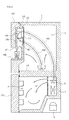
- Fig. 2 is a longitudinal sectional view of the bottom-freezer type refrigerator shown in Fig. 1, for illustrating an operation thereof;
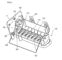
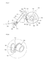
- Fig. 3 is a perspective view of an ice maker according to the present invention.
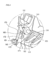
- Fig. 4 is an enlarged view of a portion A shown in Fig. 3;
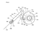
- Fig. 5 is a view illustrating a state where ice starts to be ejected from an ice maker
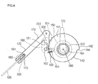
- Fig. 6 is a view illustrating a state where an ice ejection operation is terminated
- Fig. 7 is a view illustrating a state where an original position is resumed after the termination of an ice ejection operation
- Fig. 8 is a view illustrating a state where a stopping groove and a stopping protrusion are not affected by each other;
- Fig. 9 is a view illustrating a state where the stopping groove and the stopping protrusion are confined by each other;
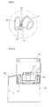
- Fig. 10 is a schematic side view of an ice maker according to the present invention.
- Fig. 11 is a left side view of a panel of an ice maker according to the present invention.
- Fig. 12 is a block diagram of a system for controlling a full-ice-state sensing device according to the present invention.
- Fig. 1 is a perspective view of a bottom-freezer type refrigerator to which the present invention is applied
- Fig. 2 is a longitudinal sectional view of the bottom-freezer type refrigerator shown in Fig. 1, for illustrating an operation thereof.
- a refrigerator 100 includes: a body 1 divided into an upper refrigerating chamber R and a lower freezing chamber F by a barrier 109; a refrigerating chamber door 103 and a freezing chamber door 101 for covering/uncovering the body 1; an insulating case 110 of a predetermined size installed in the refrigerating chamber door 103 so as to insulate a cold air of the freezing chamber F from that of the refrigerating chamber R; an ice maker 120 installed in a freezing space of the insulating case 110 so as to freeze water into ice by using a cold air supplied into the insulating case 110; an ice bank 130 for receiving ice ejected from the ice maker 120; and an outlet 107 and a dispenser 108 installed at a front surface of the refrigerating chamber door 103, for taking out ice received in the ice bank 130.
- the refrigerator 100 further includes a refrigerating cycle unit for generating a cold air necessary for refrigerating the refrigerating chamber R and the freezing chamber F.
- the refrigerating cycle unit includes a compressor 6, a condenser (not shown), an expansion valve (not shown), an evaporator 7, and a blower fan 8.
- an inner space of the insulating case 110 is further sealed with an insulating door 111.
- the insulating case 110 and the insulating door 111 are formed of an insulator so that the refrigerating chamber's cold air higher in temperature than the freezing chamber's cold air may not flow into the ice maker 120 and the ice bank 130 that are installed at an inner side of the refrigerating chamber door 103.
- the insulating case 110 is formed on an extension line of a door liner.
- a cold air inlet 105 for receiving a cold air to be used for making ice (hereinafter referred to as an ice-making cold air) and a cold air outlet 106 for discharging a cold air having been used for making ice (hereinafter referred to as a used ice-making cold air) are formed at a side of the insulating case 110.
- a cold air supply duct 102 has an end portion communicating with the cold air outlet 106 and the other end portion installed inside the barrier 109 or a side wall of the body 1.
- a cold air discharge duct 104 is installed to communicate with the cold air outlet 106 so as to discharge a used ice-making cold air of an ice-making chamber into the refrigerating chamber R.
- the cold air discharge duct 104 may be installed to discharge the used ice-making cold air into the refrigerating chamber R or the evaporator 7.
- a refrigerant is compressed from a low-temperature and high-pressure state to a high-temperature and high-pressure state while passing though the compressor 6.
- the high-temperature and high-pressure gaseous refrigerant is condensed and phase-changed into a high-temperature liquid refrigerant while passing through the condenser.
- the phase-changed high-temperature liquid refrigerant is expanded while passing through the expansion valve.
- the expanded refrigerant flows into the evaporator 7 and refrigerates its surrounding air while being phase-changed into a low-temperature and low-pressure gaseous refrigerant by absorbing the internal heat of the refrigerator 100. Thereafter, the low-temperature and low-pressure gaseous refrigerant re-flows into the compressor 6 to thereby complete a refrigerating cycle.
- a cold air that has been refrigerated by a refrigerant through heat exchange with the evaporator 7 is discharged into the refrigerator 100 by the blower fan 8 installed over the evaporator 7.
- the discharged cold air may be discharged toward the refrigerating chamber R and the freezing chamber F by being diverged by a damper.
- the cold air having been discharged toward the freezing chamber F is supplied through the cold air supply duct 102 and the cold air inlet 105 to the ice maker 120 and the ice bank 130 in the insulating case 110.
- the ice maker 120 and the ice bank 130 constitute an ice-making apparatus.
- the ice maker 120 freezes water using a cold air, and the resulting ice is ejected from the ice maker 120 by a heater (not shown) and an ejector lever (not shown) and is then received in the ice bank 130.
- the ice received in the ice bank 130 can be supplied through the outlet 107 and the dispenser 108 to users.
- a used ice-making cold air is discharged through the cold air outlet 106 and the cold air discharge duct 104 into the refrigerating chamber R to then decrease the internal temperature of the refrigerating chamber R. Also, the used ice-making cold air may be discharged toward the freezing chamber F or the evaporator 7.
- the ice maker 120 freezes water using a cold air, and the ice bank 130 receives ice ejected from the ice maker 120. A predetermined amount of ice is loaded in the ice bank 130 so that it can be fully supplied to users at all times.
- the ice bank 130 has a predetermined empty space for supplying a desired amount of ice to a user.
- the ice maker 120 senses such an ice-full state.
- the ice maker 120 and an ice-full state sensing device thereof will be descried in detail.
- Fig. 3 is a perspective view of an ice maker according to the present invention
- Fig. 4 is an enlarged view of a portion A shown in Fig. 3.
- the inventive ice-full state sensing device of the ice maker 120 includes: an ejector shaft 124 connected to a pivot (see 191 in Fig. 5) of a motor (see 191 in Fig.
- a cam 141 connected to he pivot 191 to rotate together with the ejector shaft 124; a cylindrical link 150 connected to the cam 141 at a specific friction coefficient to be selectively rotated together with the cam 141, a sub-link 160 whose rotation is restricted by the cylindrical link 150 in a state of being applied with torque a certain torque; a "L "-shaped main link 170 rotating interlocked with the sub-link 160; a terminal link 180 rotating at a rotational radius of the main link 170 in the counter direction with respect to the main link 170; and an sensing lever 128 connected to the terminal link 180 to sense the ice-full state of the ice bank 130.
- the sensing lever 128 will be simply referred to as a sensing lever.
- an ice-making mold 121 for freezing water an ejector pin 123 for lifting ice in the ice-making mold 121, and a fixing hook 125 for fixing the ice maker 120 to a door.
- water is supplied into the ice-making mold 121 and is frozen by a cold air.
- the ejector shaft 124 and the ejector pin 123 are rotated to lift ice in the ice-making mold 121, and the lifted ice is received in the ice bank 130.
- the full-ice sensing lever 128 senses the resulting ice-full state of the ice bank 130, whereby an operation of the ice maker 120 is automatically stopped.
- the ejector shaft 124 and the cam 141 are simultaneously rotated, and the cam 141 and the cylindrical link 150 are simultaneously rotated selectively.
- a frictional member (see 152 in Fig. 5) may be further provided between the cylindrical link 150 and the cam 141 so that the link 150 and the cam 141 can be relatively rotated with respect to each other.
- a stopping protrusion (see 151 in Fig. 5) is provided at a periphery of the cylindrical link 150 so that the cylindrical link 150 and the cam 141 can start to be rotated differently with respect to each other.
- a stopping groove (see 161 of Fig. 5) is formed at the sub-link 160's portion corresponding to the stopping protrusion 151.
- a guide protrusion 162 is provided to extend perpendicularly from the sub-link 160 and to contact with a periphery of the cam 141.
- a spring (see 163 in Fig. 5) is connected to an end portion of the sub-link 160 so as to always provide force for rotating the sub-link 160 counterclockwise.
- the sub-link 160 will always rotate counterclockwise by the spring 163, it cannot rotate when the guide protrusion 162 is supported by the cam 141. In this state, since the cam 141 is divided into two parts having different diameters, it can rotate within a specific angle range. Also, the stopping protrusion 151 contacts with the stopping groove 161, the sub-link 160 cannot rotate counterclockwise because it is supported also by the cylindrical link 150.
- An end portion of the main link 170 can rotate by being pushed by the guide protrusion 162.
- a slot 173 is provided at the other end portion of the main link 170 in the longitudinal direction thereof, and a protrusion 181 of the terminal link 180 is inserted into the slot 173. Since the protrusion 181 is extended from a bent portion, it causes the terminal link 180 to rotate during the rotation of the main link 170.
- the sensing lever 128 when the terminal link 180 rotates by the protrusion 181, the sensing lever 128 also simultaneously rotate, whereby an ice-full state of the ice bank 130 can be sensed.
- the sub-link 160, the main link 170 and the terminal link 180 are rotatably connected to a panel 192 by a pivot.
- the main link 170 and the sensing lever 128 will always rotate counterclockwise on a supporting point of the panel 192 due to their weights.
- the link 170 and the lever 128 may rotate by their weights or by a spring.
- Figs. 5 to 7 are side views of the ice maker from which the ice-full state sensing device is extracted.
- Fig. 5 illustrates a state where ice starts to be ejected from an ice maker
- Fig. 6 illustrates a state where an ice ejection operation is terminated
- Fig. 7 illustrates a state where an original position is resumed after the termination of an ice ejection operation.
- the cam 141 and the pivot 191 and the ejector shaft 124 rotate counterclockwise (that is, in a forward direction) by the driving of a motor (see 222 in Fig. 11).
- the ejector pin 123 protruding perpendicularly from the ejector shaft 124 also simultaneously rotates to transfer ice in the ice-making mold 121 to the ice bank 130.
- the ejector shaft 124 rotates by at least 270° for the ice-ejecting operation during the transition from the state of Fig. 5 to the state of Fig. 6.
- the cam 141, the pivot 191 and the cylindrical link 150 are supported by and rotated on a first pivot point 300.
- the sub-link 160 is supported by and rotated on a second pivot point 301, the main link 170 a third pivot point 302, and the terminal link 180 a fourth pivot point 303.
- the motor and the pivot 191 rotate.
- the cylindrical link 150 also rotates by a frictional force because the frictional member 152 is interposed between the cam 141 and the cylindrical link 150.
- the frictional member 152 may be formed between the cylindrical link 150 and the cam 141, or between the cylindrical link 150 and the pivot 191, in such a way that the cylindrical link 150 can rotate relatively with respect to the pivot 191 and the cam 141.
- the full-ice sensing lever 128 senses whether or not the ice bank 130 is fully filled with ice.
- the sub-link 160 will rotate counterclockwise by the spring 163. However, when the stopping protrusion 151 of the cylindrical link 150 is caught in the stopping protrusion 161 of the sub-link 160 or when the guide protrusion 162 protruding perpendicularly from the sub-link 160 contacts with a second circumferential surface 143 of the cam 141, the counterclockwise rotation of the sub-link 160 is restricted.
- the cam 141 has formed thereon a first circumferential surface 142 and the second circumferential surface 143 whose outer diameter is smaller than that of the surface 142. Also, a round jaw 144 is provided at a contact position between the surfaces 142 and 143. Accordingly, when the cam 141 rotates by a predetermined angle, whether or not the sub-link 150 can rotate is determined by a radius difference between the surfaces 142 and 143.
- the sub-link 150 continue to stop at a previous position because the stopping protrusion 151 is caught in the stopping groove 161.
- a shot link 171 of the main link 170 which is adjacent to a rotational direction of the guide protrusion 162, also continues to stop due to confinement by the sub-link 160.
- the terminal link 180 connected to the main link 170 also maintains its current position, and the sensing lever 128 connected to the terminal link 180 also maintains its initial state where it does not move.
- the sensing lever 128 does not operate and thus the lever 128 and ice do not interfere with each other during the ice-ejecting operation.
- the shot link 171 of the main link 170 is pushed by the guide protrusion 162 of the sub-link 160 to thereby rotate counterclockwise by a rotation angle of the sub-link 160, and a long link 172 oppositely connected to the pivot also rotates counterclockwise.
- the sensing lever 128 inserted and connected into the terminal link 180 also rotates clockwise. That is, the sensing lever 128 locates in the ice bank 130 in its initial state, and senses an ice-full state of the ice bank 130 when it rotates clockwise.
- the rotation angle of the sensing lever 128 can be greatly amplified by the terminal link 180. That is, as a distance between the fourth pivot point 303 and the protrusion 181 becomes shorter, the terminal link 180 can rotate by a greater angle even when the main link 180 rotates by the same angle. Therefore, by adjusting the distance between the fourth pivot point 303 and the protrusion 181, the rotation angle of the sensing lever 128 can be conveniently adjusted.
- the guide protrusion 162 moves to its original position and the shot link 171 of the main link 170 returns to its original position by the weight of the main link 170.
- the short link 171 may return to its original position by a separate spring of the main link 170.
- the long link 172 of the main link 170 rotates clockwise and simultaneously the terminal link 180 rotates counterclockwise. Accordingly, the sensing lever 128 also moves counterclockwise to return to its initial position.
- the sensing lever 128 can return to its initial position. However, if the ice bank 130 is fully filled with ice, the sensing lever 128 cannot move downward (that is, counterclockwise) and return to its initial position due to the fully-loaded ice, and is confined at an upper position. When the sensing lever 128 cannot return to its initial position, the ice-maker 120 determines that the ice bank 130 has been fully filled with ice to thereby stop its operation. Accordingly, when the ice bank 130 has been fully filled with ice, the ice maker 120 does not make any more ice.
- the inventive ice-full state sensing device can reliably sense the ice-full sate of the ice bank 130 disposed below the ice maker 120. Also, even though the sensing lever 128 is short, the ice-full state sensing device can reliably sense the ice-full state of the ice bank 130 because the sensing lever 128 is installed at the ice maker 120's lower side adjacent to an upper side of the ice bank 130.
- Fig. 10 is a schematic side view of the ice maker according to the present invention.
- the sensing lever 128 is provided to have a trajectory radius identical to or smaller than the horizontal width of the ice bank 130 and to reliably sense the ice-full state of the ice bank 130.
- a rotational radius L of the sensing lever 128 does not deviate from a left end portion of the ice bank 130 as shown in Fig. 10.
- Fig. 11 is a left side view of a panel of an ice maker according to the present invention
- Fig. 12 is a block diagram of a system for controlling the full-ice-state sensing device according to the present invention.
- a sensor unit for sensing a position of the sensing lever 128 includes first and second hall sensors 201 and 202, and first and second magnets 231 and 232.
- the first hall sensor 201 and the first magnet 231 constitute a first sensing unit
- the second hall sensor 202 and the second magnet 232 constitute a second sensing unit.
- a driven gear 222 engaged with the driving gear 221 When a driving gear 221 rotates by a torque of a motor 220, a driven gear 222 engaged with the driving gear 221 repeatedly rotates clockwise or counterclockwise at a predetermined period.
- the first magnet 231 is installed at a side of the driven gear 222, and the first hall sensor 201 is installed at the panel 192 (or an equivalent substrate) at a position facing the first magnet 231.
- the ejector shaft 124 is installed coaxially with a pivot 191 of the driven gear 222.
- the ejector shaft 134 According to the clockwise or counterclockwise rotation of the driven gear 222, the ejector shaft 134 also rotate together with the driven gear 222.
- the first hall sensor 201 When the first magnet 231 reaches a position where the first hall sensor 201 can sense it (hereinafter simply referred to as a "sensing position"), the first hall sensor 201 generates a sensing signal indicating that an initial position of the ejector shaft 124 is sensed.
- the first hall sensor 201 and the first magnet 231 are installed at a position where the initial position of the ejector shaft 124 can be sensed.
- the cam 141 is rotatably installed on the pivot 191 and rotates. In order to vertically move the sensing lever 128, the torque of the cam 141 is transferred through the cylindrical link 150, the sub-link 160, the main link 170 and the terminal link 180 to the sensing lever 128.
- the terminal link 180 is interlocked with the sensing lever 128.
- the sensing lever 128 has an elongated portion 129 at the other end portion thereof and pivots according to the rotational direction of the main link 170.
- the second magnet 232 is installed at the elongated portion 129 of the sensing lever 128 and the second hall sensor 202 for detecting the position of the second magnet 232 is installed at the panel 192 or an equivalent fixed substrate.
- the second hall sensor 202 is installed at a predetermined position such that the sensing lever 128 can sense the ice-full state. Accordingly, when the second magnet 232 reaches a sensing position for the second hall sensor 202, the second hall sensor 202 outputs a sensing signal for determining whether or not an ice-full state has occurred.
- the hall sensor 202 senses the position of the second magnet 232 and outputs a sensing signal. At this time, when the sensing signal from the second hall sensor 202 is detected longer than a predetermined time period, it is determined that an ice-full state has occurred.
- a controller 200 outputs a driving signal to a hall sensor power supply unit 210 to supply power to the first and second hall sensors 201 and 202.
- the hall sensors 201 and 202 become a standby state for sensing the magnets 231 and 232.
- the controller 200 determines whether or not a sensing signal is outputted from the hall sensors 201.
- the controller 200 controls a water supply unit 212 to supply water to the ice-making mold of the ice maker.
- the first hall sensor 201 senses the first magnet 231 and outputs a predetermined sensing signal to the controller 200.
- the controller 200 determines the position of the ejector shaft 124 by using the initial position sensing signal, and recognizes whether or not a water supply operation and an ice-ejecting operation is completed.
- the controller 200 controls a motor driving unit 211 to drive the motor 220 and the gears 221 and 222. Accordingly, an ice-ejecting operation is initiated.
- a clockwise and counterclockwise rotation of the motor 220 is repeated periodically within a predetermined angle range. This rotational radius can be applied to an ice-making mold cover.
- the second hall sensor 202 senses a state where the sensing lever 128 is located at an ice-full state sensing position. In this state, when sensing the second magnet 232, the second hall sensor 202 outputs a sensing signal.
- a sensing signal indicating that the second magnet 232 is sensed by the second hall sensor 202 is outputted, and the sensing lever 128 returns to a lower position by the counterclockwise rotation of the cam 141. That is, when the ice bank 130 is not fully filled with ice, the sensing signal from the second hall sensor 202 is terminated within a predetermined time period. On the contrary, when the ice bank 130 is fully filled with ice, the controller 200 detects that the sensing signal from the second hall sensor 202 is maintained longer than the predetermined time period and determines that an ice-full state is generated.
- This vertical movement of the sensing lever 128 for the ice-full state sensing operation is repeated periodically when the cam 114 is clockwise or counterclockwise rotated by the torque of motor 220 for the ice-ejecting operation.
- the sensing lever 128 having moved to the upper position remains at the upper position even when the rotation of the gears 221 and 222 according to the ice-ejecting operation is terminated. This is because the sensing lever 128 is caught in the ice of the ice bank 130.
- the second hall sensor 202 senses the second magnet 232 and continuously outputs a sensing signal longer than the predetermined time period.
- the controller 200 continuously receives a sensing signal from the second hall sensor 202, and determines that an ice-full state is generated when detecting, by using a time counter 203, that the sensing signal is maintained longer than a predetermined time period.
- the predetermined time period may be set to a time period necessary for the counterclockwise rotation of the motor 220.
- the controller 200 In response to the ice-full state sensing signal from the second hall sensor 202, the controller 200 terminates an ice-making operation and an ice-ejecting operation and then becomes a standby state for waiting for the sensing lever to return to its initial state. At this time, when the sensing lever 128 returns to its original position due to a discharge of ice, the ice maker 120 can initiate its operation.
- the present invention aims at installing the ice-making apparatus at an inner side of the refrigerator chamber door or the freezing chamber door and then sensing the ice-full state of the ice tank. It should be apparent to those skilled in the art that the construction and operation of the present invention can be applied to a top-mount type refrigerator having a freezing chamber and a refrigerating chamber partitioned up and down, a side-by-side type having a freezing chamber and a refrigerating chamber partitioned left and right as well as a bottom-freezer type refrigerator having a freezing chamber and a refrigerating chamber partitioned up and down.
- the refrigerator is classified into a top mount-type refrigerator having a freezing chamber and a cold chamber partitioned up and down, a bottom freezer-type refrigerator having a cold chamber and a freezing chamber partitioned up and down, and a side-by-side type refrigerator having a freezing chamber and a cold chamber partitioned left and right.
- the present invention can reduce the length of the ice-full state sensing lever and the size of the ice-making device, thereby making it possible to solve a problem of deficiency in an inner space of a refrigerator.
- the ice-full state lever is not interfered with ice of the ice bank during the clockwise rotation thereof and operates only during the counterclockwise operation thereof, whereby a problem of its interference with ice can be solved.
- the ice-making apparatus can be shallowly installed in an inner surface of a refrigerator door, whereby an insulating thickness of the refrigerator can be increased.
Landscapes
- Engineering & Computer Science (AREA)
- Physics & Mathematics (AREA)
- Mechanical Engineering (AREA)
- Thermal Sciences (AREA)
- General Engineering & Computer Science (AREA)
- Production, Working, Storing, Or Distribution Of Ice (AREA)
Applications Claiming Priority (2)
| Application Number | Priority Date | Filing Date | Title |
|---|---|---|---|
| KR2004035293 | 2004-05-18 | ||
| KR1020040035293A KR100671567B1 (ko) | 2004-05-18 | 2004-05-18 | 냉장고용 제빙기의 만빙 감지 장치 |
Publications (3)
| Publication Number | Publication Date |
|---|---|
| EP1598617A2 true EP1598617A2 (fr) | 2005-11-23 |
| EP1598617A3 EP1598617A3 (fr) | 2011-10-26 |
| EP1598617B1 EP1598617B1 (fr) | 2017-01-18 |
Family
ID=34942303
Family Applications (1)
| Application Number | Title | Priority Date | Filing Date |
|---|---|---|---|
| EP05291058.5A Ceased EP1598617B1 (fr) | 2004-05-18 | 2005-05-17 | Appareil de fabrication de glace et détecteur d'un niveau maximum de remplissage de glace |
Country Status (3)
| Country | Link |
|---|---|
| US (1) | US7237393B2 (fr) |
| EP (1) | EP1598617B1 (fr) |
| KR (1) | KR100671567B1 (fr) |
Cited By (3)
| Publication number | Priority date | Publication date | Assignee | Title |
|---|---|---|---|---|
| AU2007201299B2 (en) * | 2006-03-27 | 2008-10-02 | Lg Electronics Inc | Ice making system for refrigerator |
| RU2468313C2 (ru) * | 2008-06-26 | 2012-11-27 | Хайер Груп | Холодильник с льдогенератором |
| EP1916489A3 (fr) * | 2006-10-20 | 2014-11-26 | LG Electronics Inc. | Appareil de fabrication de glace |
Families Citing this family (34)
| Publication number | Priority date | Publication date | Assignee | Title |
|---|---|---|---|---|
| US7266951B2 (en) * | 2004-10-26 | 2007-09-11 | Whirlpool Corporation | Ice making and dispensing system |
| US7337620B2 (en) * | 2005-05-18 | 2008-03-04 | Whirlpool Corporation | Insulated ice compartment for bottom mount refrigerator |
| DE102005057139A1 (de) * | 2005-11-30 | 2007-06-06 | BSH Bosch und Siemens Hausgeräte GmbH | Eisbereiter und damit ausgestattetes Haushaltsgerät |
| US7712322B2 (en) * | 2006-02-15 | 2010-05-11 | Maytag Corporation | Ice level sensing device for an automatic ice maker in a refrigerator |
| KR100767844B1 (ko) * | 2006-07-11 | 2007-10-17 | 엘지전자 주식회사 | 냉장고 |
| KR101377151B1 (ko) | 2006-12-07 | 2014-03-25 | 삼성전자주식회사 | 냉장고 |
| KR20080061173A (ko) * | 2006-12-28 | 2008-07-02 | 엘지전자 주식회사 | 냉장고 |
| US7757511B2 (en) * | 2006-12-29 | 2010-07-20 | Whirlpool Corporation | Refrigerated drawer having an icemaker |
| US20080155997A1 (en) * | 2006-12-29 | 2008-07-03 | Whirlpool Corporation | Refrigerated drawer having an icemaker |
| KR20080068440A (ko) | 2007-01-19 | 2008-07-23 | 삼성전자주식회사 | 제빙장치 및 이를 갖춘 냉장고 |
| CN101315240A (zh) * | 2008-06-26 | 2008-12-03 | 海尔集团公司 | 一种制冰机及包含该制冰机的冰箱 |
| US20110023510A1 (en) * | 2008-08-04 | 2011-02-03 | Lg Electronics Inc. | Ice maker and refrigerator having the same |
| US9175893B2 (en) * | 2008-11-10 | 2015-11-03 | General Electric Company | Refrigerator |
| US20100326096A1 (en) * | 2008-11-10 | 2010-12-30 | Brent Alden Junge | Control sytem for bottom freezer refrigerator with ice maker in upper door |
| US9200828B2 (en) * | 2008-11-10 | 2015-12-01 | General Electric Company | Refrigerator |
| KR101580448B1 (ko) * | 2009-01-14 | 2015-12-29 | 삼성전자 주식회사 | 냉장고 및 그 제어방법 |
| DE102009000664A1 (de) * | 2009-02-06 | 2010-08-12 | BSH Bosch und Siemens Hausgeräte GmbH | Eisbereiter |
| KR20100110183A (ko) * | 2009-04-02 | 2010-10-12 | 엘지전자 주식회사 | 제빙장치 및 이를 구비한 냉장고 및 이 냉장고의 제빙방법 |
| KR101645356B1 (ko) * | 2010-09-20 | 2016-08-12 | 동부대우전자 주식회사 | 냉장고용 제빙기 |
| US8893523B2 (en) * | 2010-11-22 | 2014-11-25 | General Electric Company | Method of operating a refrigerator |
| JP5536621B2 (ja) * | 2010-11-29 | 2014-07-02 | 日本電産サーボ株式会社 | 自動製氷装置 |
| KR101888197B1 (ko) * | 2011-09-16 | 2018-08-14 | 엘지전자 주식회사 | 냉장고 |
| WO2013169058A1 (fr) * | 2012-05-10 | 2013-11-14 | 주식회사 에스씨디 | Appareil et procédé permettant de commander une machine à glaçons d'un réfrigérateur |
| KR101962139B1 (ko) * | 2013-01-03 | 2019-03-26 | 엘지전자 주식회사 | 아이스메이커 및 그 제어방법 |
| KR101678310B1 (ko) * | 2015-07-27 | 2016-11-21 | 주식회사 에스 씨디 | 제빙기 구동 장치 및 방법 |
| KR102382460B1 (ko) * | 2017-09-13 | 2022-04-05 | 엘지전자 주식회사 | 냉장고 및 냉장고의 제빙장치 |
| KR102426182B1 (ko) * | 2017-11-10 | 2022-07-29 | 엘지전자 주식회사 | 냉장고 |
| KR102660521B1 (ko) * | 2018-11-16 | 2024-04-24 | 엘지전자 주식회사 | 아이스 메이커 및 냉장고 |
| EP4306879A3 (fr) * | 2018-11-16 | 2024-04-03 | LG Electronics Inc. | Machine à glaçons et réfrigérateur |
| AU2019378525A1 (en) * | 2018-11-16 | 2021-06-24 | Lg Electronics Inc. | Ice maker and refrigerator |
| EP4300013A3 (fr) * | 2018-11-16 | 2024-03-13 | LG Electronics Inc. | Appareil à glaçons et réfrigérateur |
| WO2020101370A1 (fr) | 2018-11-16 | 2020-05-22 | 엘지전자 주식회사 | Machine à glaçons et réfrigérateur |
| KR20210124816A (ko) | 2020-04-07 | 2021-10-15 | 삼성전자주식회사 | 냉장고 |
| KR20250151875A (ko) | 2024-04-15 | 2025-10-22 | 주식회사 대창 | 제빙기 및 이를 포함하는 냉장고 |
Family Cites Families (10)
| Publication number | Priority date | Publication date | Assignee | Title |
|---|---|---|---|---|
| US3635043A (en) * | 1970-03-16 | 1972-01-18 | Gen Electric | Household refrigerator including automatic icemaker and door mounted ice storage receptacle |
| US3964269A (en) * | 1974-11-21 | 1976-06-22 | Whirlpool Corporation | Sensing arm water fill shut off for ice maker |
| US5261248A (en) * | 1992-02-24 | 1993-11-16 | Whirlpool Corporation | Fill cup sleeve for a recoverable domestic icemaker |
| JP2727280B2 (ja) * | 1992-09-04 | 1998-03-11 | 株式会社三協精機製作所 | 製氷皿の振動装置 |
| JP3572175B2 (ja) | 1997-09-12 | 2004-09-29 | 株式会社東芝 | 自動製氷装置 |
| US6637217B2 (en) * | 2000-12-30 | 2003-10-28 | Lg Electronics Inc. | Ice maker for refrigerator and control method thereof |
| KR100577184B1 (ko) * | 2003-05-28 | 2006-05-10 | 엘지전자 주식회사 | 냉장고 |
| EP1491833A1 (fr) * | 2003-06-25 | 2004-12-29 | Lg Electronics Inc. | Bac à accumulation de glace pour un générateur de glace d'un réfrigérateur |
| KR100565624B1 (ko) * | 2003-09-25 | 2006-03-30 | 엘지전자 주식회사 | 자동제빙기용 이젝터의 회전 제어장치 |
| KR100693578B1 (ko) * | 2003-11-27 | 2007-03-14 | 엘지전자 주식회사 | 냉장고용 아이스 메이커 |
-
2004
- 2004-05-18 KR KR1020040035293A patent/KR100671567B1/ko not_active Expired - Fee Related
-
2005
- 2005-05-17 US US11/130,164 patent/US7237393B2/en not_active Expired - Lifetime
- 2005-05-17 EP EP05291058.5A patent/EP1598617B1/fr not_active Ceased
Cited By (4)
| Publication number | Priority date | Publication date | Assignee | Title |
|---|---|---|---|---|
| AU2007201299B2 (en) * | 2006-03-27 | 2008-10-02 | Lg Electronics Inc | Ice making system for refrigerator |
| US7770404B2 (en) | 2006-03-27 | 2010-08-10 | Lg Electronics Inc. | Ice making system for refrigerator |
| EP1916489A3 (fr) * | 2006-10-20 | 2014-11-26 | LG Electronics Inc. | Appareil de fabrication de glace |
| RU2468313C2 (ru) * | 2008-06-26 | 2012-11-27 | Хайер Груп | Холодильник с льдогенератором |
Also Published As
| Publication number | Publication date |
|---|---|
| US20050257536A1 (en) | 2005-11-24 |
| KR20050110330A (ko) | 2005-11-23 |
| EP1598617A3 (fr) | 2011-10-26 |
| US7237393B2 (en) | 2007-07-03 |
| KR100671567B1 (ko) | 2007-01-18 |
| EP1598617B1 (fr) | 2017-01-18 |
Similar Documents
| Publication | Publication Date | Title |
|---|---|---|
| EP1598617B1 (fr) | Appareil de fabrication de glace et détecteur d'un niveau maximum de remplissage de glace | |
| US7134292B2 (en) | Full ice level sensing apparatus and method | |
| EP2401564B1 (fr) | Appareil de réfrigération | |
| US8820108B2 (en) | Refrigerator including ice maker | |
| US9341407B2 (en) | Apparatus for storing ice and method for controlling same | |
| EP1772688B1 (fr) | Détecteur pour déterminer le remplissage complet de glaçon | |
| US20100319367A1 (en) | Ice maker, refrigerator having the same, and ice making method thereof | |
| US11619434B2 (en) | Ice maker and refrigerator including the same | |
| US11585583B2 (en) | Ice maker and refrigerator including the same | |
| KR20190091034A (ko) | 아이스메이커 및 이를 포함하는 냉장고 | |
| EP2049855B1 (fr) | Procédé de détection d'eau pour fabrication de glace dans un réfrigérateur | |
| US20240280307A1 (en) | Refrigerator and method for controlling the same | |
| US20240093928A1 (en) | Refrigerator and control method therefor | |
| US11029070B2 (en) | Ice maker and refrigerator including the same | |
| KR20050063871A (ko) | 냉장고용 아이스 메이커 및 아이스 메이커의 이빙 제어방법 | |
| KR20190091033A (ko) | 아이스메이커 및 이를 포함하는 냉장고 | |
| KR20190032899A (ko) | 아이스메이커 및 이를 포함하는 냉장고 | |
| KR20090109420A (ko) | 냉장고 제빙기의 만빙 감지 장치 | |
| KR100600726B1 (ko) | 냉장고의 제빙기 |
Legal Events
| Date | Code | Title | Description |
|---|---|---|---|
| PUAI | Public reference made under article 153(3) epc to a published international application that has entered the european phase |
Free format text: ORIGINAL CODE: 0009012 |
|
| AK | Designated contracting states |
Kind code of ref document: A2 Designated state(s): AT BE BG CH CY CZ DE DK EE ES FI FR GB GR HU IE IS IT LI LT LU MC NL PL PT RO SE SI SK TR |
|
| AX | Request for extension of the european patent |
Extension state: AL BA HR LV MK YU |
|
| PUAL | Search report despatched |
Free format text: ORIGINAL CODE: 0009013 |
|
| AK | Designated contracting states |
Kind code of ref document: A3 Designated state(s): AT BE BG CH CY CZ DE DK EE ES FI FR GB GR HU IE IS IT LI LT LU MC NL PL PT RO SE SI SK TR |
|
| AX | Request for extension of the european patent |
Extension state: AL BA HR LV MK YU |
|
| RIC1 | Information provided on ipc code assigned before grant |
Ipc: G01F 23/00 20060101ALI20110920BHEP Ipc: F25C 5/18 20060101AFI20110920BHEP Ipc: G05D 9/00 20060101ALI20110920BHEP |
|
| 17P | Request for examination filed |
Effective date: 20120413 |
|
| AKX | Designation fees paid |
Designated state(s): DE FR GB |
|
| 17Q | First examination report despatched |
Effective date: 20120703 |
|
| GRAP | Despatch of communication of intention to grant a patent |
Free format text: ORIGINAL CODE: EPIDOSNIGR1 |
|
| INTG | Intention to grant announced |
Effective date: 20160920 |
|
| GRAS | Grant fee paid |
Free format text: ORIGINAL CODE: EPIDOSNIGR3 |
|
| STAA | Information on the status of an ep patent application or granted ep patent |
Free format text: STATUS: GRANT OF PATENT IS INTENDED |
|
| GRAA | (expected) grant |
Free format text: ORIGINAL CODE: 0009210 |
|
| STAA | Information on the status of an ep patent application or granted ep patent |
Free format text: STATUS: THE PATENT HAS BEEN GRANTED |
|
| AK | Designated contracting states |
Kind code of ref document: B1 Designated state(s): DE FR GB |
|
| REG | Reference to a national code |
Ref country code: GB Ref legal event code: FG4D |
|
| REG | Reference to a national code |
Ref country code: FR Ref legal event code: PLFP Year of fee payment: 13 |
|
| REG | Reference to a national code |
Ref country code: DE Ref legal event code: R096 Ref document number: 602005051181 Country of ref document: DE |
|
| REG | Reference to a national code |
Ref country code: DE Ref legal event code: R097 Ref document number: 602005051181 Country of ref document: DE |
|
| PLBE | No opposition filed within time limit |
Free format text: ORIGINAL CODE: 0009261 |
|
| STAA | Information on the status of an ep patent application or granted ep patent |
Free format text: STATUS: NO OPPOSITION FILED WITHIN TIME LIMIT |
|
| 26N | No opposition filed |
Effective date: 20171019 |
|
| REG | Reference to a national code |
Ref country code: FR Ref legal event code: PLFP Year of fee payment: 14 |
|
| PGFP | Annual fee paid to national office [announced via postgrant information from national office to epo] |
Ref country code: GB Payment date: 20220405 Year of fee payment: 18 Ref country code: FR Payment date: 20220413 Year of fee payment: 18 Ref country code: DE Payment date: 20220405 Year of fee payment: 18 |
|
| REG | Reference to a national code |
Ref country code: DE Ref legal event code: R119 Ref document number: 602005051181 Country of ref document: DE |
|
| GBPC | Gb: european patent ceased through non-payment of renewal fee |
Effective date: 20230517 |
|
| PG25 | Lapsed in a contracting state [announced via postgrant information from national office to epo] |
Ref country code: DE Free format text: LAPSE BECAUSE OF NON-PAYMENT OF DUE FEES Effective date: 20231201 Ref country code: GB Free format text: LAPSE BECAUSE OF NON-PAYMENT OF DUE FEES Effective date: 20230517 |
|
| PG25 | Lapsed in a contracting state [announced via postgrant information from national office to epo] |
Ref country code: FR Free format text: LAPSE BECAUSE OF NON-PAYMENT OF DUE FEES Effective date: 20230531 |