EP1598631A1 - Procédé et système pour ajuster la trajectoire d'un projectile non guidé avec compensation du biais de tremblement - Google Patents
Procédé et système pour ajuster la trajectoire d'un projectile non guidé avec compensation du biais de tremblement Download PDFInfo
- Publication number
- EP1598631A1 EP1598631A1 EP05010353A EP05010353A EP1598631A1 EP 1598631 A1 EP1598631 A1 EP 1598631A1 EP 05010353 A EP05010353 A EP 05010353A EP 05010353 A EP05010353 A EP 05010353A EP 1598631 A1 EP1598631 A1 EP 1598631A1
- Authority
- EP
- European Patent Office
- Prior art keywords
- projectile
- launch tube
- flight path
- flight
- impulse vector
- Prior art date
- Legal status (The legal status is an assumption and is not a legal conclusion. Google has not performed a legal analysis and makes no representation as to the accuracy of the status listed.)
- Withdrawn
Links
Images






Classifications
-
- F—MECHANICAL ENGINEERING; LIGHTING; HEATING; WEAPONS; BLASTING
- F41—WEAPONS
- F41G—WEAPON SIGHTS; AIMING
- F41G3/00—Aiming or laying means
- F41G3/12—Aiming or laying means with means for compensating for muzzle velocity or powder temperature with means for compensating for gun vibrations
-
- F—MECHANICAL ENGINEERING; LIGHTING; HEATING; WEAPONS; BLASTING
- F41—WEAPONS
- F41G—WEAPON SIGHTS; AIMING
- F41G3/00—Aiming or laying means
- F41G3/10—Aiming or laying means with means for compensating for canting of the trunnions
-
- F—MECHANICAL ENGINEERING; LIGHTING; HEATING; WEAPONS; BLASTING
- F41—WEAPONS
- F41G—WEAPON SIGHTS; AIMING
- F41G7/00—Direction control systems for self-propelled missiles
- F41G7/20—Direction control systems for self-propelled missiles based on continuous observation of target position
- F41G7/30—Command link guidance systems
- F41G7/301—Details
- F41G7/306—Details for transmitting guidance signals
Definitions
- the present invention relates to a method and system for adjusting the flight path of an unguided projectile, immediately after launching, in order to compensate for inaccuracies that result from barrel jittering during the projectile firing.
- the present invention provides a method for adjusting the flight path of an unguided projectile, comprising:
- the flight correction unit comprises a plurality of pyrotechnic thrusters provided with said projectile.
- the present invention is also directed to a system for adjusting the flight path of an unguided projectile, comprising:
- the flight correction unit comprises a plurality of pyrotechnic thrusters, each of said thrusters being mounted at a different angular disposition with respect to the longitudinal axis of the projectile such that the axis of each of said thrusters crosses the longitudinal axis of the projectile.
- the means for determining the activation time of said thrusters is a device for measuring the angular displacement of the projectile about its longitudinal axis from said ejection time to a predetermined flight path correction time.
- said device comprises:
- the present invention is also directed to a launcher system, comprising:
- the present invention is also directed to an unguided projectile system, comprising:
- the projectile system further comprises a processing means for receiving said compensating impulse vector from said communication means and for synchronizing ignition of two of said thrusters at a predetermined flight path correction time, the adjusted flight path thereby essentially coinciding with a nominal flight path.
- the projectile processing means is further adapted to generate an adjusted impulse vector, said adjusted impulse vector being based on said compensating impulse vector and on an incremental impulse vector which compensates for the angular displacement of the projectile measured by said device, two of said thrusters capable of being activated at said predetermined flight path correction time, such that the thrust developed thereby is suitable for adjusting the flight path of said projectile by a magnitude and direction substantially equal to that of said compensating impulse vector.
- the projectile is preferably formed with elements that radially protrude from the projectile fuselage, said elements being insertable within complementary grooves formed within said launch tube, during loading of the projectile within the launcher, and being adapted for preventing rotation of the projectile within said launch tube, prior to the ejection time.
- the present invention relates to a method and system for adjusting the flight path of an unguided projectile, immediately after launching, in order to compensate for inaccuracies that result from barrel recoil or jittering during the projectile firing. It will be understood that the term "jittering" throughout the specification also refers to recoil.
- Fig. 1 schematically illustrates an exemplary projectile launcher, generally designated by numeral 10, in which a projectile, generally designated by numeral 30, is loaded.
- Launcher 10 may be fixed onto the barrel of a rifle, may be an independent unit, may be portable such as being a shoulder-carried launcher, or may be deployed in several types of naval or aircraft weaponry.
- the illustrated projectile launcher 10 is configured as a Davis gun for obtaining a reduced jittering, with a solid propellant 12 and compensating mass 14 being loaded in launch tube 8, rearward to projectile 30.
- the launcher 10 does not necessarily have to be of this type and can be of any unguided projectile launcher known in the art.
- projectile 30 is accelerated forward at a tremendously high rate, which may be as much as 10,000 g for an aircraft-launched missile, and propellant 12 is converted into a gaseous state, causing compensating mass 14 to be ejected rearward through the launch tube, thereby reducing the jittering of launcher 10.
- the jittering is nevertheless noticeable and causes a deviation in the flight path from a desired target.
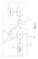
- Fig. 3 describes a block diagram of system 40 of the invention.
- the system of the present invention comprises the following components, according to a preferred embodiment:
- measuring unit 16 comprises the following sensors, which are mounted on launcher 10:
- sensor 21 senses that the projectile has been ejected from the launch tube and accordingly provides data to ground processing unit 17, which is indicative of the projectile ejection.
- ground processing unit 17 establishes ejection time t 1 .
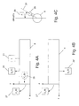
- measuring unit 16 senses three deviation values: angular sight deviation A, launch tube attitude deviation ?á, which is a reflection of the magnitude of the launch tube jittering, and projectile velocity deviation ?V x , all of which will be described hereinafter with respect to Fig. 6.
- the system of the invention is adapted to generate a compensating impulse vector, which compensates for each deviation so that the projectile may return to a nominal flight path.
- sight angle sensor 29 determines the angular deviation A of launcher sight 25.
- Ground processing unit 17 then reduces the angular deviation A into components along the y and z axes, and first deviation value 42 (Fig. 6) is therefore determined.
- the launch tube jitters at ejection time t 1 .
- Sensors 27 and 27' measure the angular velocity along the x-y and x-z planes, respectively, of the launch tube tip and sensors 28 and 28' measure the acceleration of the launch tube tip along axes y and z, respectively, at time t 1 .
- Ground processing unit 17 integrates the sensed values of the acceleration and angular velocity transmitted thereto by the corresponding sensors at ejection time t 1 and determines thereby the actual attitude á 1 of the launch tube relative to a horizontal plane H, which is schematically illustrated in Fig. 5, and the velocity of the launch tube tip at time t 1 .
- the actual attitude is compared with the nominal attitude and second deviation value 43 (Fig. 6) equal to launch tube attitude deviation ?á, along each of the y and z axes, is determined.
- Ground processing unit 17 also determines third deviation value 44 (Fig. 6) concerning projectile velocity v 1 along the x axis at ejection time t 1 , and compares this value with the nominal velocity.
- the ground processing unit determines a vector which compensates for the projectile velocity deviation in the x axis, between v 1 and the nominal velocity (?V x ), and reduces this compensating vector into components in the y and z axes.
- processing unit 17 determines an impulse value, which is equal to the product of the mass of the projectile and a difference in velocity, for correcting each of the corresponding deviation values 42, 43 and 44, so that the projectile may return to the nominal flight path and finally strike the intended target.
- Processing unit 17 generates a pair of impulse components, one on each of the y and z axes, for each of the deviation values, e.g. I y2 and I z2 .
- Each pair of impulse components is generated in such a way that if no other deviation values resulted, the application of said pair of impulse components onto the center of gravity (CG) of the projectile (Fig. 2) would cause the projectile to return to its nominal flight path.
- CG center of gravity
- Ground processing unit 17 then combines all of the impulse components along the y axis to produce combined impulse component I y and combines all of the impulse components along the z axis to produce combined impulse component I z .
- a weighted impulse vector I w is then generated from combined impulse components I y and I z .
- Ground processing unit 17 then generates a signa! 25 representative of said weighted impulse vector, and transmits this signal via transmitter 18 (Fig. 3) to the projectile in flight.
- signal 25 is transmitted to receiver 33 carried by the projectile. According to the present invention, this signal is transmitted very shortly after launching, in the range of approximately 0.2 seconds after firing, in order to minimize inaccuracies.
- Signal 25 may be transmitted by wireless means, by a fiber optic cable connecting transmitter 18 and receiver 33, which is severed shortly after ejection of the projectile from the launch tube, or any other means of communication well known to those skilled in the art.
- Projectile processing unit 37 receives signal 25 and commands flight correcting unit 32 to apply the compensating impulse vector at the correct instant, so that the actual flight path of the projectile may be corrected to coincide with the nominal flight path and so that the projectile warhead may accurately strike a selected target.
- Flight path correction in accordance with the present invention is dependent upon accurate application of the compensating impulse vector. Since the projectile rotates about its longitudinal axis while in flight in order to reduce drifting, flight correcting unit 32 rotates as well. If the angular displacement of the flight correcting unit following projectile ejection time t 1 were unknown, the compensating impulse vector would be liable to be applied at an incorrect direction, and the flight path would not be corrected.
- Projectile processing unit 37 receives data from angular rotation sensor 35 concerning the angular displacement of the projectile following time t 1 , and accordingly adjusts the impulse vector that is to be applied to the projectile.
- the adjusted impulse vector that is to be applied to the projectile is weighted impulse vector I w combined with an incremental impulse vector that takes into account the difference in angular position of the flight correcting unit between time t 1 and the time at which flight correction is effected, hereinafter referred to as time t 2 .
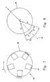
- Fig. 7 illustrates a preferred embodiment of flight correcting unit 32.
- Flight correcting unit 32 is mounted on a cylindrical portion 45 of the projectile body, which is preferably, but not necessarily at the rear of the projectile.
- Flight correcting unit 32 comprises a plurality of pyrotechnic thrusters 47, e.g. miniature jet engines, each of which is mounted to the portion 45 of the projectile body, at a different orientation with respect to longitudinal axis 31 of the projectile (Fig. 2) such that the axis of each of said thrusters crosses longitudinal axis 31 of the projectile.
- Five pyrotechnic thrusters 47 are shown, but it will be appreciated that any other number of thrusters from two to five which is suitable for controlling the magnitude and direction of the adjusted impulse vector may be similarly employed.
- the projectile rotates about its longitudinal axis while in flight at a typical angular rate ù of approximately 5-10 Hz, and this rotational rate may be utilized to fire a thruster at a precise angle which is predetermined by processing unit 37. Therefore thrusters 47 are not adapted to accelerate the projectile any more than the acceleration imparted by the launcher, but rather are used to change the orientation of the projectile, so that it may accurately impact a selected target. By one-time firing of a selected number of thrusters, and at the appropriate orientation, the magnitude and direction of the adjusted impulse vector are controllable.
- Fig. 8 schematically depicts the generation of an adjusted impulse vector I.
- Two thrusters separated by an angular distance of 2â were fired. Since each thruster is identical, the impulse vector generated by each thruster has an equal magnitude of I 1 and is directed inward to center C of portion 45 of the projectile body.
- the resultant impulse vector I is equal to 2 I 1 sinâ and is collinear with the centerline 49 between the two thrusters, directed outwardly from center C. It will be appreciated that any other number of thrusters may be fired, and the resultant impulse vector will be similarly determined from the total number of individual components.
- Figs. 9 and 10 illustrate angular rotation sensor 35, which is used to measure the angular displacement of the projectile about its longitudinal axis.
- Angular rotation sensor 35 comprises disc 51 provided with collar 57, which is coaxial with longitudinal axis 31 of the projectile. Collar 57 facilitates the mounting of disc 51 on bearing block 53, which is fixedly attached to fuselage 58 of the projectile by means of adaptor 54, so that disc 51 is rotatable about bearing block 53.
- the rim of disc 51 is provided with a weighted portion 56, which is adapted to reduce the angular velocity of disc 51.
- Weighted portion 56 is normally separated from an abutment surface (not shown), which is a part of the fuselage.
- Disc 51 is formed with a plurality of apertures 63, which are formed at a uniform radial distance from disc center 64 and are at a fixed angular distance with respect to centerline 65 one from the other.
- Light detector 61 e.g. an encoder, is mounted onto fuselage 58 and emits a beam of light that is directed to one of the apertures.
- the projectile During launching, the projectile is accelerated within the launch tube and is prevented from rotating, so that the angular orientation of a datum provided with disc 51 may be determined at ejection time t 1 .
- one or more protrusions 67 radially protrude from fuselage 58 of the projectile. These protrusions 67 are insertable, during loading of the projectile, in complementary grooves 69 formed in the tubular inner wall of launch tube 8. During forward propulsion of the projectile, protrusions 67 slide within grooves 69, and the projectile is therefore prevented from rotating within launch tube 8.
- disc 51 is pressed to the abutment surface as a result of the acceleration of the projectile during launching and is therefore unable to rotate.
- the projectile Upon ejection of the projectile from the launch tube at time t 1 , the projectile ceases to accelerate and is propelled along a flight path under the influence of momentum, as a result of its initial velocity V 1 at time t 1 , and of gravity. Since disc 51 ceases to be accelerated after being ejected from the launch tube, it is no longer pressed against the abutment surface and is therefore free to rotate.
- disc 51 While the projectile begins to rotate about its longitudinal axis after ejection, due to the configuration of the projectile and to the airstreams that pass therearound, the angular rotation of disc 51 is significantly limited by weighted portion 56, e.g. is on the order of approximately 1 revolution per hour. Thus disc 51 may be considered stationary relative to fuselage 58. Since light detector 61 is connected to fuselage 58, in-flight rotation of the projectile about its longitudinal axis results in rotation of the light detector about the longitudinal axis of the projectile. Light emitted from light detector 61 onto apertures 63 of the relatively stationary disc 51 is therefore indicative of the degree of angular rotation of the disc.
- Light detector 61 transmits the data concerning the angular difference of datum 66 from time t 1 , at which the projectile begins to rotate relative to the disc, to predetermined flight path correction time t 2 to processing unit 37 (Fig. 3), whereupon the signal received from transmitter 18 is adjusted and the adjusted impulse vector is applied to the projectile center of gravity by means of flight correcting unit 32, as described hereinabove.
- projectile processing unit 37 may also adjust a compensating impulse vector by taking into account the time difference between ejection time t 1 and the flight path correction time t 2 .
- Signal 25 is representative of the compensating impulse vector, which is generated by ground processing unit 17 (Fig. 3), in order to correct the projectile position at time t 1 due to the presence of deviation values 42, 43 and 44 (Fig. 6).
- the projectile position invariably changes from time t 1 to time t 2 , a time of approximately 0.05 sec, and therefore the resultant impulse vector I (Fig. 8) generated at flight path correction time t 2 may result in an inaccurate strike.
- a clock (not shown), which is in communication with projectile processing unit 37 (Fig. 3), measures the time difference between t 1 and t 2 .
- Projectile processing unit 37 (Fig. 3) accordingly adjusts the required impulse vector based on the difference in the projectile position between t 1 and t 2 .
Landscapes
- Engineering & Computer Science (AREA)
- General Engineering & Computer Science (AREA)
- Chemical & Material Sciences (AREA)
- Combustion & Propulsion (AREA)
- Aiming, Guidance, Guns With A Light Source, Armor, Camouflage, And Targets (AREA)
Applications Claiming Priority (2)
| Application Number | Priority Date | Filing Date | Title |
|---|---|---|---|
| IL16202704 | 2004-05-17 | ||
| IL162027A IL162027A (en) | 2004-05-17 | 2004-05-17 | Method and system for resetting the flight path of a non-guided bullet, including compensation for deviation from the oscillations of the launcher |
Publications (1)
| Publication Number | Publication Date |
|---|---|
| EP1598631A1 true EP1598631A1 (fr) | 2005-11-23 |
Family
ID=34936449
Family Applications (1)
| Application Number | Title | Priority Date | Filing Date |
|---|---|---|---|
| EP05010353A Withdrawn EP1598631A1 (fr) | 2004-05-17 | 2005-05-12 | Procédé et système pour ajuster la trajectoire d'un projectile non guidé avec compensation du biais de tremblement |
Country Status (3)
| Country | Link |
|---|---|
| US (1) | US7467761B2 (fr) |
| EP (1) | EP1598631A1 (fr) |
| IL (1) | IL162027A (fr) |
Cited By (2)
| Publication number | Priority date | Publication date | Assignee | Title |
|---|---|---|---|---|
| WO2010108917A1 (fr) * | 2009-03-24 | 2010-09-30 | Dynamit Nobel Defence Gmbh | Détermination de la vitesse initiale d'un projectile |
| US20250102274A1 (en) * | 2023-09-22 | 2025-03-27 | Ex Corporation Oy | Sight |
Families Citing this family (12)
| Publication number | Priority date | Publication date | Assignee | Title |
|---|---|---|---|---|
| US8014678B2 (en) * | 2006-06-14 | 2011-09-06 | Verizon Patent And Licensing Inc. | Power supply |
| DE102007007929B3 (de) * | 2007-02-17 | 2008-11-20 | Lfk-Lenkflugkörpersysteme Gmbh | Infanteristisches Waffensystem zum Bekämpfen von feststehenden Zielen mittels aus Werfern verschossenen lenkbaren Granaten |
| US7898009B2 (en) * | 2007-02-22 | 2011-03-01 | American Semiconductor, Inc. | Independently-double-gated transistor memory (IDGM) |
| US8155819B2 (en) * | 2007-08-13 | 2012-04-10 | Raytheon Company | System and method for effecting vehicle maneuver to compensate for IMU error |
| EP2307846B1 (fr) * | 2008-06-02 | 2016-05-04 | Causwave, Inc. | Système de propulsion de projectile |
| US20090308274A1 (en) * | 2008-06-11 | 2009-12-17 | Lockheed Martin Corporation | Integrated Pusher Plate for a Canister- or Gun-Launched Projectile and System Incorporating Same |
| US8245624B1 (en) | 2009-08-31 | 2012-08-21 | The United States Of America As Represented By The Secretary Of The Navy | Decoupled multiple weapon platform |
| IL211142A (en) | 2011-02-09 | 2015-06-30 | Yesaiahu Redler | A system and method for measuring the motion parameters of a sling when exiting the barrel |
| DE102012020740B4 (de) * | 2012-10-23 | 2014-11-13 | Diehl Bgt Defence Gmbh & Co. Kg | Verfahren zum Umrüsten einer Munition für eine schulterstützbare Waffe |
| US9574843B2 (en) * | 2014-02-27 | 2017-02-21 | Magnetospeed Llc | Apparatus for correcting trajectories of projectiles launched from firearms |
| US20170307334A1 (en) * | 2016-04-26 | 2017-10-26 | Martin William Greenwood | Apparatus and System to Counter Drones Using a Shoulder-Launched Aerodynamically Guided Missile |
| CN114322920B (zh) * | 2021-12-31 | 2025-01-07 | 武汉武船计量试验有限公司 | 一种发射管中心角度测量方法 |
Citations (4)
| Publication number | Priority date | Publication date | Assignee | Title |
|---|---|---|---|---|
| US1108717A (en) | 1913-07-07 | 1914-08-25 | Ordnance Dev Company | Fixed ammunition for use on air-craft. |
| US3807274A (en) | 1970-08-07 | 1974-04-30 | Subcom Inc | Method for launching objects from submersibles |
| GB2140538A (en) * | 1983-05-17 | 1984-11-28 | Ferranti Plc | Projectile guidance system |
| US5423242A (en) * | 1989-03-10 | 1995-06-13 | Schuemann; Wilfred C. | Hybrid ported firearm |
Family Cites Families (14)
| Publication number | Priority date | Publication date | Assignee | Title |
|---|---|---|---|---|
| US2822755A (en) * | 1950-12-01 | 1958-02-11 | Mcdonnell Aircraft Corp | Flight control mechanism for rockets |
| US3749334A (en) * | 1966-04-04 | 1973-07-31 | Us Army | Attitude compensating missile system |
| GB1605295A (en) * | 1967-12-13 | 1988-06-08 | Secr Defence | Rocket projectiles |
| US4023749A (en) * | 1975-12-08 | 1977-05-17 | The United States Of America As Represented By The Secretary Of The Army | Directional control system for artillery missiles |
| FR2447320A1 (fr) * | 1979-01-23 | 1980-08-22 | Matra | Perfectionnements aux procedes et dispositifs d'amortissement actif de nutation pour vehicule spatial |
| FR2578665B1 (fr) * | 1981-06-04 | 1988-02-12 | Aerospatiale | Procede de pilotage d'un missile a faible vitesse, systeme d'arme et missile pour la mise en oeuvre du procede |
| US4899956A (en) * | 1988-07-20 | 1990-02-13 | Teleflex, Incorporated | Self-contained supplemental guidance module for projectile weapons |
| FR2657687B1 (fr) * | 1990-01-26 | 1994-05-27 | Thomson Brandt Armements | Munition anti-char et son procede d'utilisation. |
| DE4210113C1 (de) * | 1992-03-27 | 1998-11-05 | Athanassios Dr Ing Zacharias | Verfahren zum Leiten eines Flugkörpers und Flugkörper |
| DE4325218C2 (de) * | 1993-07-28 | 1998-10-22 | Diehl Stiftung & Co | Artillerie-Rakete und Verfahren zur Leistungssteigerung einer Artillerie-Rakete |
| IL118883A (en) * | 1996-07-17 | 2000-06-01 | Israel State | Flight control of an airborne vehicle at low velocity |
| US6138945A (en) * | 1997-01-09 | 2000-10-31 | Biggers; James E. | Neural network controller for a pulsed rocket motor tactical missile system |
| US6347763B1 (en) * | 2000-01-02 | 2002-02-19 | The United States Of America As Represented By The Secretary Of The Army | System and method for reducing dispersion of small rockets |
| JP2004306762A (ja) * | 2003-04-07 | 2004-11-04 | Mitsubishi Heavy Ind Ltd | 三軸姿勢制御用推進装置及びその装置を備えた飛行物体 |
-
2004
- 2004-05-17 IL IL162027A patent/IL162027A/en unknown
-
2005
- 2005-05-12 EP EP05010353A patent/EP1598631A1/fr not_active Withdrawn
- 2005-05-13 US US11/128,654 patent/US7467761B2/en not_active Expired - Lifetime
Patent Citations (4)
| Publication number | Priority date | Publication date | Assignee | Title |
|---|---|---|---|---|
| US1108717A (en) | 1913-07-07 | 1914-08-25 | Ordnance Dev Company | Fixed ammunition for use on air-craft. |
| US3807274A (en) | 1970-08-07 | 1974-04-30 | Subcom Inc | Method for launching objects from submersibles |
| GB2140538A (en) * | 1983-05-17 | 1984-11-28 | Ferranti Plc | Projectile guidance system |
| US5423242A (en) * | 1989-03-10 | 1995-06-13 | Schuemann; Wilfred C. | Hybrid ported firearm |
Cited By (4)
| Publication number | Priority date | Publication date | Assignee | Title |
|---|---|---|---|---|
| WO2010108917A1 (fr) * | 2009-03-24 | 2010-09-30 | Dynamit Nobel Defence Gmbh | Détermination de la vitesse initiale d'un projectile |
| US8800359B2 (en) | 2009-03-24 | 2014-08-12 | Dynamit Nobel Defense GmbH | Determination of the muzzle velocity of a projectile |
| US20250102274A1 (en) * | 2023-09-22 | 2025-03-27 | Ex Corporation Oy | Sight |
| US12435951B2 (en) * | 2023-09-22 | 2025-10-07 | Ex Corporation Oy | Sight |
Also Published As
| Publication number | Publication date |
|---|---|
| US20060060692A1 (en) | 2006-03-23 |
| US7467761B2 (en) | 2008-12-23 |
| IL162027A0 (en) | 2005-11-20 |
| IL162027A (en) | 2009-05-04 |
Similar Documents
| Publication | Publication Date | Title |
|---|---|---|
| EP0809781B1 (fr) | Procede et dispositif permettant une correction de trajectoire pour poussee radiale pour un projectile ballistique | |
| US7467761B2 (en) | Method and system for adjusting the flight path of an unguided projectile, with compensation for jittering deviation | |
| US7834300B2 (en) | Ballistic guidance control for munitions | |
| US8450668B2 (en) | Optically guided munition control system and method | |
| US6832740B1 (en) | Missile system and method of missile guidance | |
| US5685504A (en) | Guided projectile system | |
| EP1281038B1 (fr) | Methode et systeme de simulateur de tir de precision | |
| US4542870A (en) | SSICM guidance and control concept | |
| US6565036B1 (en) | Technique for improving accuracy of high speed projectiles | |
| US7533849B2 (en) | Optically guided munition | |
| US3868883A (en) | Guidance system | |
| JPH0215795B2 (fr) | ||
| US20010025901A1 (en) | Method and system for guiding submunitions | |
| NO327414B1 (no) | Vapensystem for presisjonsstyrt hypersonisk prosjektil | |
| US6629668B1 (en) | Jump correcting projectile system | |
| US6138944A (en) | Scatterider guidance system for a flying object based on maintenance of minimum distance between the designating laser beam and the longitudinal axis of the flying object | |
| CN114502465B (zh) | 通过脉冲信标和低成本惯性测量单元确定姿态 | |
| Morrison et al. | Guidance and control of a cannon-launched guided projectile | |
| JPS6239442B2 (fr) | ||
| US4898340A (en) | Apparatus and method for controlling a cannon-launched projectile | |
| US4530270A (en) | Method of directing a close attack missile to a target | |
| US11300670B2 (en) | Weapon on-board velocity and range tracking | |
| CN211012682U (zh) | 一种40mm火箭筒发射的激光驾束制导导弹 | |
| US4938115A (en) | Arrangement in a flying weapons carrier for combating ground targets | |
| Phillips et al. | Pulse motor optimization via mission charts for an exoatmospheric interceptor |
Legal Events
| Date | Code | Title | Description |
|---|---|---|---|
| PUAI | Public reference made under article 153(3) epc to a published international application that has entered the european phase |
Free format text: ORIGINAL CODE: 0009012 |
|
| AK | Designated contracting states |
Kind code of ref document: A1 Designated state(s): AT BE BG CH CY CZ DE DK EE ES FI FR GB GR HU IE IS IT LI LT LU MC NL PL PT RO SE SI SK TR |
|
| AX | Request for extension of the european patent |
Extension state: AL BA HR LV MK YU |
|
| 17P | Request for examination filed |
Effective date: 20060104 |
|
| AKX | Designation fees paid |
Designated state(s): AT BE BG CH CY CZ DE DK EE ES FI FR GB GR HU IE IS IT LI LT LU MC NL PL PT RO SE SI SK TR |
|
| 17Q | First examination report despatched |
Effective date: 20090203 |
|
| STAA | Information on the status of an ep patent application or granted ep patent |
Free format text: STATUS: THE APPLICATION IS DEEMED TO BE WITHDRAWN |
|
| 18D | Application deemed to be withdrawn |
Effective date: 20121201 |