EP1598891A2 - Brennstoffzelle - Google Patents
Brennstoffzelle Download PDFInfo
- Publication number
- EP1598891A2 EP1598891A2 EP05010743A EP05010743A EP1598891A2 EP 1598891 A2 EP1598891 A2 EP 1598891A2 EP 05010743 A EP05010743 A EP 05010743A EP 05010743 A EP05010743 A EP 05010743A EP 1598891 A2 EP1598891 A2 EP 1598891A2
- Authority
- EP
- European Patent Office
- Prior art keywords
- electrode
- fuel
- oxidant
- solid electrolyte
- fuel cell
- Prior art date
- Legal status (The legal status is an assumption and is not a legal conclusion. Google has not performed a legal analysis and makes no representation as to the accuracy of the status listed.)
- Withdrawn
Links
Images

Classifications
-
- H—ELECTRICITY
- H01—ELECTRIC ELEMENTS
- H01M—PROCESSES OR MEANS, e.g. BATTERIES, FOR THE DIRECT CONVERSION OF CHEMICAL ENERGY INTO ELECTRICAL ENERGY
- H01M4/00—Electrodes
- H01M4/86—Inert electrodes with catalytic activity, e.g. for fuel cells
- H01M4/8647—Inert electrodes with catalytic activity, e.g. for fuel cells consisting of more than one material, e.g. consisting of composites
- H01M4/8657—Inert electrodes with catalytic activity, e.g. for fuel cells consisting of more than one material, e.g. consisting of composites layered
-
- H—ELECTRICITY
- H01—ELECTRIC ELEMENTS
- H01M—PROCESSES OR MEANS, e.g. BATTERIES, FOR THE DIRECT CONVERSION OF CHEMICAL ENERGY INTO ELECTRICAL ENERGY
- H01M4/00—Electrodes
- H01M4/86—Inert electrodes with catalytic activity, e.g. for fuel cells
- H01M4/8605—Porous electrodes
-
- H—ELECTRICITY
- H01—ELECTRIC ELEMENTS
- H01M—PROCESSES OR MEANS, e.g. BATTERIES, FOR THE DIRECT CONVERSION OF CHEMICAL ENERGY INTO ELECTRICAL ENERGY
- H01M8/00—Fuel cells; Manufacture thereof
- H01M8/04—Auxiliary arrangements, e.g. for control of pressure or for circulation of fluids
- H01M8/04082—Arrangements for control of reactant parameters, e.g. pressure or concentration
- H01M8/04197—Preventing means for fuel crossover
-
- Y—GENERAL TAGGING OF NEW TECHNOLOGICAL DEVELOPMENTS; GENERAL TAGGING OF CROSS-SECTIONAL TECHNOLOGIES SPANNING OVER SEVERAL SECTIONS OF THE IPC; TECHNICAL SUBJECTS COVERED BY FORMER USPC CROSS-REFERENCE ART COLLECTIONS [XRACs] AND DIGESTS
- Y02—TECHNOLOGIES OR APPLICATIONS FOR MITIGATION OR ADAPTATION AGAINST CLIMATE CHANGE
- Y02E—REDUCTION OF GREENHOUSE GAS [GHG] EMISSIONS, RELATED TO ENERGY GENERATION, TRANSMISSION OR DISTRIBUTION
- Y02E60/00—Enabling technologies; Technologies with a potential or indirect contribution to GHG emissions mitigation
- Y02E60/30—Hydrogen technology
- Y02E60/50—Fuel cells
Definitions
- This invention generally relates to a fuel cell. More particularly, this invention pertains to a fuel cell including a proton-conducting solid electrolyte membrane.
- a fuel cell such as a polymer electrolyte fuel cell is expected to expand in the future as a power source for a vehicle or a stationary generator.
- a known polymer electrolyte fuel cell includes a proton-conducting solid electrolyte membrane, a fuel electrode provided on one side of the solid electrolyte membrane, and an oxidant electrode provided on the other side of the solid electrolyte membrane,
- fuel such as hydrogen and methanol is supplied to the fuel electrode while oxidant gas is supplied to the oxidant electrode.
- Fuel is oxidized in the fuel electrode so as to generate proton and electron. Proton reaches a counter electrode, i.e. the oxidant electrode by passing through the solid electrolyte membrane.
- Electron reaches the oxidant electrode by passing through an external load, instead of the solid electrolyte membrane. Then, the proton and the electron that has reached the oxidant electrode generate water by reacting with oxygen supplied to the oxidant electrode. Accordingly, electrical energy is collected by such power generation reaction.
- fuel (hydrogen) and oxidant (oxygen) supplied to the fuel cell do not permeate the inside of the solid electrolyte membrane.
- hydrogen or oxygen may pass through the solid electrolyte membrane and leaks to the respective counter electrodes. In this case, a fuel cell output may be decreased.
- a reaction speed of hydrogen with oxygen for generating water decreases since in a case where an electrode potential of the oxidant electrode is high, a catalytic property of a platinum catalyst used for the oxidant electrode relative to hydrogen oxidation decreases. Therefore, a state occurs in which hydrogen and oxygen exist in the oxidant electrode. In this state, if the oxidant electrode potential is lowered, hydrogen and oxygen rapidly react with each other, thereby causing damage to the polymer electrolyte membrane.
- fuel or oxidant is prevented from reaching the respective counter electrodes by passing through the solid electrolyte membrane, and mixing with each other (i.e. oxygen and hydrogen are mixed with each other) inside the respective counter electrodes. Therefore, decrease of the fuel cell output and lifetime thereof caused by leakage may be prevented.
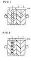
- FIG. 1 is a representative schematic view of a fuel cell 1 according to the present embodiment.
- a membrane electrode assembly 10 of the fuel cell 1 includes a proton-conducting solid electrolyte membrane 2 formed by polymer material, an oxidant electrode 3 provided on one side of the solid electrolyte membrane 2 in a thickness direction thereof, and a fuel electrode 4 provided on the other side of the solid electrolyte membrane 2 in a thickness direction thereof.
- the fuel electrode 4 includes a catalyst layer facing the solid electrolyte membrane 2, and a porous gas diffusion layer through which fuel diffuses and passes.
- the catalyst layer is formed by a mixture of a catalyst having catalytic property, and a proton-conducting electrolyte component.
- the oxidant electrode 3 includes a polarization system.
- the polarization system is preferably formed by a permeation resistance portion 7 having proton conductivity and electron conductivity, as well as permeation resistance to permeation of fuel or oxidant.
- the permeation resistance (i.e. a gas barrier ability) of the permeation resistance portion 7 is acquired by increasing density of electrode components, and by impregnating an inside of the electrode mainly with solid electrolyte components and/or conductive material.
- the proton conductivity of the permeation resistance portion 7 is acquired by impregnating an inside of the electrode mainly with solid electrolyte components.
- the electron conductivity is acquired by conductive fiber such as carbon fiber, or conductive material such as carbon black.
- the oxidant electrode 3 includes therein the permeation resistance portion 7 as mentioned above.
- the oxidant electrode 3 basically includes a porous outer layer portion 6 having diffusive permeability for diffusing and permeating oxidant containing gas (i.e. oxygen containing gas, normally), a permeation resistance portion 7 having proton conductivity and electron conductivity, as well as resistance to permeation of oxidant containing gas (i.e. gas barrier ability), and an inner layer portion 8 including a catalyst having catalytic property.
- the outer layer portion 6 preferably includes catalyst so as to have catalytic property.
- oxidant oxygen containing gas, normally
- fuel hydrogen containing gas, normally
- Fuel is oxidized in the fuel electrode 4, thereby generating proton and electron.
- the proton reaches a counter electrode, i.e. the oxidant electrode 3, by passing through the solid electrolyte membrane 2.
- the electron reaches the oxidant electrode 3 by passing through an external load (not shown), instead of the solid electrolyte membrane 2, from the fuel electrode 4.
- the proton and electron that have reached the oxidant electrode 3 generate water by reacting with oxygen supplied to the oxidant electrode 3. Electrical energy is thus collected by such power generation reaction. Since excess hydrogen exists in the fuel electrode 4, an electrode potential thereof may be relatively low as is close to a value of an electrode potential of a hydrogen electrode.
- An electrode potential of the inner layer portion 8 of the oxidant electrode 3 may be relatively low as is close to a value of an electrode potential of hydrogen electrode.
- the electrode potential of the outer layer portion 6 of the oxidant electrode 3 is relatively higher than that of the inner layer portion 8 while the electrode potential of the inner layer portion 8 of the oxidant electrode 3 is relatively lower than that of the outer layer portion 6.
- the permeation resistance portion 7 has electron conductivity as well as resistance (i.e. gas barrier ability) to permeation of gas such as oxidant containing gas.
- the permeation resistance portion 7 electrically connects the outer layer portion 6 having a relatively high potential with the inner layer portion 8 having a relatively low potential, which constitute the oxidant electrode 3, so that a closed circuit is formed.
- the electrode potential of the inner layer portion 8 of the oxidant electrode 3 is electrochemically polarized in a positive direction relative to a resting potential of the inner layer portion 8 so that oxidization ability for oxidizing hydrogen may be enhanced.
- Hydrogen that has moved from the fuel electrode 4 to the inner layer portion 8 by passing through the solid electrolyte membrane 2 in the direction of the arrow A is oxidized to become protons (H + ). That is, hydrogen gas that has leaked from the fuel electrode 4 by passing through the solid electrolyte membrane 2 exists in the oxidant electrode 3 as protons (H + ), not as hydrogen gas.
- protons (H + ) generated by oxidation of hydrogen that have moved from the fuel electrode 4 to the oxidant electrode 3 by passing through the solid electrolyte membrane 2 is conducted in the permeation resistance portion 7 having proton conductivity towards the outer layer portion 6 in the direction of an arrow A2.
- the protons (H + ) receive electrons and then generate water by reacting with oxygen supplied to the outer layer portion 6 of the oxidant electrode 3, by means of catalytic action provided in the oxidant electrode 3.
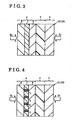
- a fuel cell 1B according to the present embodiment shown in Fig. 2 has a same structure as that of the fuel cell 1 shown in Fig. 1.
- the fuel cell 1B includes a proton-conducting solid electrolyte membrane 2, an oxidant electrode 3 provided on one side of the solid electrolyte membrane 2 in a thickness direction thereof, and a fuel electrode 4 provided on the other side of the solid electrolyte membrane 2 in a thickness direction thereof.
- the oxidant electrode 3 includes an outer layer portion 6 having diffusive permeability for diffusing and permeating oxidant containing gas, a permeation resistance portion 7 having proton conductivity and resistance to permeation of the oxidant gas, and an inner layer portion 8 provided between the solid electrolyte membrane 2 and the permeation resistance portion 7 and having catalytic property.
- conductors 5 having electron conductivity are partially provided inside the permeation resistance portion 7. That is, the permeation resistance portion 7 including the conductors 5 can configure the polarization system.
- the conductor 5 may be formed by conductive fiber such as carbon fiber, an assembly of conductive material such as carbon black, and the like.
- a membrane electrode assembly 10 of a fuel cell 1C includes a proton-conducting solid electrolyte membrane 2, an oxidant electrode 3 provided on one side of the solid electrolyte membrane 2 in a thickness direction thereof, and a fuel electrode 4 provided on the other side of the solid electrolyte membrane 2 in a thickness direction thereof.
- the fuel electrode 4 includes an outer layer portion 6 having diffusive permeability of fuel, a permeation resistance portion 7 having proton conductivity, electron conductivity, and resistance (i.e. fuel barrier ability) to permeation of fuel, and an inner layer portion 8 provided between the solid electrolyte membrane 2 and the permeation resistance portion 7 and including catalyst having catalytic property.
- oxidant containing gas oxygen containing gas, normally
- fuel hydrogen containing gas, normally
- Fuel is oxidized in the fuel electrode 4, thereby generating proton and electron.
- the proton reaches a counter electrode, i.e. the oxidant electrode 3, by passing through the solid electrolyte membrane 2.
- the electron reaches the oxidant electrode 3 by passing through an external load (not shown), instead of the solid electrolyte membrane 2, from the fuel electrode 4.
- the proton and electron that have reached the oxidant electrode 3 generate water by reacting with oxygen supplied to the oxidant electrode 3. Electrical energy is thus collected by such power generation reaction.
- An electrode potential of the inner layer portion 8 of the fuel electrode 4 may be relatively high. That is, in Fig. 3, the electrode potential of the outer layer portion 6 of the fuel electrode 4 is relatively lower than that of the inner layer portion 8 while the electrode potential of the inner layer portion 8 of the fuel electrode 4 is relatively higher than that of the outer layer portion 6.
- the permeation resistance portion 7 has electron conductivity as well as proton conductivity and resistance (i.e. fuel barrier ability) to permeation of fuel.
- the permeation resistance portion 7 electrically connects the outer layer portion 6 having a relatively low potential with the inner layer portion 8 having a relatively high potential, which constitute the fuel electrode 4, so that a closed circuit is formed.
- the electrode potential of the inner layer portion 8 of the fuel electrode 4 is electrochemically polarized in a negative direction relative to a resting potential of the inner layer portion 8 so that reduction ability for reducing excess oxygen may be enhanced.
- the reduction ability for reducing oxygen that has permeated from the oxidant electrode 3 into the inner layer portion 8 of the fuel electrode 4 via the solid electrolyte membrane 2 is enhanced. That is, oxygen leaking from the oxidant electrode 3 to the fuel electrode 4 by passing through the solid electrolyte membrane 2, and hydrogen supplied to the outer layer portion 6 of the fuel electrode 4 are prevented from being mixed with each other.
- a membrane electrode assembly 10 of a fuel cell 1D includes a fuel electrode 4 that includes an outer layer portion 6 having diffusive permeability of fuel, a permeation resistance portion 7 having proton conductivity and resistance to permeation of fuel, and an inner layer portion 8 provided between the solid electrolyte membrane 2 and the permeation resistance portion 7 and including catalyst having catalytic property.
- conductors 5 having electron conductivity are partially provided inside the permeation resistance portion 7. That is, the permeation resistance portion 7 including the conductors 5 can configure the polarization system.
- the aforementioned polarization system is provided at least one of the oxidant electrode 3 and the fuel electrode 4.
- the polarization system is formed by the permeation resistance portion 7 having permeation resistance (i.e. bas barrier ability) to permeation of fuel or oxidant, as well as proton conductivity and electron conductivity.
- the permeation resistance portion 7 may be formed by arranging resistive material to permeation of fuel or oxidant at a vent hole portion of at least one of the oxidant electrode 3 and the fuel electrode 4.
- proton-conducting electrolyte composition, catalyst such as platinum catalyst, or conductive material such as carbon black is used as the resistive material to permeation of fuel or oxidant.
- vent hole portion of at least one of the oxidant electrode 3 and the fuel electrode 4 may be impregnated with aforementioned material.
- a permeation resistance portion 7 may be formed by a layer having resistance to permeation of fuel or oxidant that is sandwiched between the inner layer portion 8 and the outer layer portion 6.
- a tetrafluoroethylene dispersion solution (20% by weight) was mixed with carbon black particle (VULCAN XC72R manufactured by Cabot Corporation) and a small amount of surface-active agent, and sufficiently stirred to combine to thereby obtain a mixture. Then, in order to evaporate excess water, the mixture was heated and dried so that granular carbon material with fluorocarbon resin (i.e. conductive material with fluorocarbon resin) was formed. An assembly of thus-manufactured carbon material with fluorocarbon resin was sufficiently mixed up to form a sheet (thickness: approximately 50 ⁇ m). This sheet was temporally burned for 2 hours at 150 °C.
- the sheet was burned for approximately 1 hour at a temperature equal to or greater than 360°C (precisely, between 360° C and 390°C) so as to produce a sheet forming member 200 consisting of water-repellent carbon material (see Fig. 5).
- the sheet forming member 200 includes a vent hole portion.
- a platinum catalyst as a catalyst HISPEC 4000 manufactured by Johnson Matthey PLC
- a polymer solid electrolyte solution SS1100 manufactured by Asahi Kasei
- proton-conducting electrolyte component a platinum catalyst as a catalyst
- the catalyst paste was spread on a first side face 201 and a second side face 202 of the sheet forming member 200 respectively so that both side faces 201 and 202 were impregnated with the catalyst paste, and then the sheet forming member 200 was dried. Afterwards, the sheet forming member 200 was vacuum-dried at 80°C for a predetermined time period (precisely, 5 hours or more).
- the thus-produced sheet forming member 200 was impregnated with the electrolyte component and catalyst. Therefore, the sheet forming member 200 has proton conductivity and electron conductivity as well as gas barrier ability (gas permeation resistance).
- the sheet forming member 200 forms the permeation resistance portion 7 and the inner layer portion 8 shown in Fig. 1.
- the permeation resistance portion 7 is formed by impregnating the vent hole portion of the oxidant electrode 3 with resistive material to permeation of oxidant (i.e. catalyst paste mainly composed of catalyst and polymer solid electrolyte solution).
- a piece of a predetermined size i.e. approximately 10cm 2
- One side face of the cutout piece was impregnated with a tetrafluoroethylene dispersion solution (equivalent to the one mentioned above).
- the cutout piece configures the permeation resistance portion 7 and the inner layer portion 8 shown in Fig. 1.
- a commercially available fluorocarbon electrolyte membrane (thickness: 30 ⁇ m, size: approximately 7cm 2 ) was arranged next to the other side face of the cutout piece as the solid electrolyte membrane 2.
- a carbon paper power collecting member (carbon paper manufactured by TORAY, thickness: 180 ⁇ m, size: 10cm 2 ), which had been burnt so as to have water-repellent quality, was arranged on one side face of the cutout piece as the porous outer layer portion 6 having gas diffusive permeability.
- the catalyst paste which was mainly composed of polymer solid electrolyte solution including proton-conducting electrolyte component and platinum catalyst, and produced in an aforementioned manner, was applied on the porous carbon paper power collecting member having gas permeability, which was also produced in an aforementioned manner.
- the carbon paper power collecting member with the catalyst paste was then dried so that the fuel electrode 4 shown in Fig. 1 was formed.
- the fuel electrode 4 includes a catalyst layer facing the solid electrolyte membrane 2 and a gas diffusion layer provided in a position not facing the solid electrolyte membrane 2.
- the fuel electrode 4 was arranged on a face of the solid electrolyte membrane 2 opposite to the face where the cutout piece was arranged, thereby forming a lamination.
- the lamination is formed by the solid electrolyte membrane 2, the oxidant electrode 3, and the fuel electrode 4, both of which sandwich the solid electrolyte membrane 2 therebetween.
- the lamination was pressed by means of a hot-press machine at 160°C and 7.85Mpa for approximately 90 seconds, thereby obtaining a membrane electrode assembly 10 (see Figs. 1 and 6).
- the inner layer portion 8 includes a catalyst having catalytic property for changing hydrogen to proton, the hydrogen being leaked from the fuel electrode 4 by passing through the solid electrolyte membrane 2. Further, the inner layer portion 8 includes proton conductivity for conducting the proton to move towards the permeation resistance portion 7.
- the permeation resistance portion 7 is not expected to have gas diffusion ability but has gas permeation resistance (gas barrier ability).
- the permeation resistance portion 7 has proton conductivity as well as electron conductivity for electrically connecting the inner layer portion 8 and the outer layer portion 6.
- the outer layer portion 6 is of porous formed by an assembly of carbon fiber and having gas diffusive permeability for permeating oxygen gas.
- an experimental fuel cell is configured by sandwiching the membrane electrode assembly 10 between the gas distribution plates 101 and 102.
- the gas distribution plate 101 includes a passage 101a for oxidant while the gas distribution plate 102 includes a passage 102a for fuel.
- air is supplied to the outer layer portion 6 of the oxidant electrode 3 of the fuel cell to thereby constitute a cathode (oxidant electrode), while hydrogen gas as fuel is supplied to the fuel electrode 4 to thereby constitute an anode (fuel electrode).
- a gas chromatograph analyzer was connected to a gas exhaust port of the cathode of the fuel cell for analyzing a concentration of hydrogen gas leaking from the anode to the cathode through the membrane electrode assembly 10.
- an amount of hydrogen gas leaking to the oxidant electrode 3 side was below a detection limit value.
- the open circuit voltage of the fuel cell was 0.92V.
- a gas chromatograph analyzer was connected to a gas exhaust port of the cathode of a fuel cell for comparison (herein after called “comparison fuel cell”).
- This comparison fuel cell was basically same as the fuel cell shown in Fig. 6, however, the permeation resistance portion 7 was not provided.
- An electrode size of the comparison fuel cell was 10cm 2 that is same as the present embodiment.
- the hydrogen and air, humidified with a gas bubbler filled with pure water at 80°C were respectively supplied at a rate of 200 ml per minute to the comparison fuel cell that was thermally maintained at 80 °C.
- an amount of hydrogen gas leaking to the oxidant electrode 3 side was approximately 350ppm, which was greater than that obtained by the present embodiment.
- the open circuit voltage of the fuel cell was approximately 1V. Air and hydrogen gas were both at normal pressure in the present embodiment and the comparison example.
- air as oxidant gas permeates diffusively through the outer layer portion 6 of the oxidant electrode 3.
- excess oxygen exists in the outer layer portion 6 and at the same time the electrode potential thereof may be high.
- the permeation resistance portion 7 having gas barrier ability (gas permeation resistance)
- air supplied to the outer layer portion 6 is limited to pass through the inner layer portion 8 from the outer layer portion 6.
- oxygen is prevented from permeating and reaching at a catalyst arranged in the vicinity of an interface between the inner layer portion 8 and the solid electrolyte membrane 2.
- hydrogen that has permeated the solid electrolyte membrane 2 from the fuel electrode 4 to the inter layer potion 8 side is excessive.
- the electrode potential of the inner layer portion 8 of the oxidant electrode 3 is close to the electrode potential of the hydrogen electrode, i.e. becomes low.
- the permeation resistance portion 7 has electron conductivity and proton conductivity as well as gas permeability resistance. Therefore, the inner layer portion 8 having a low electrode potential and the outer layer portion 6 having a high electrode potential are electrically connected to each other by means of the permeation resistance portion 7, thereby forming the electrically closed circuit. As a result, the electrode potential of the inner layer portion 8 of the oxidant electrode 3 is electrochemically polarized in a positive direction relative to a resting potential. The ability for oxidizing hydrogen is enhanced. Thus, hydrogen gas that has reached the inner layer portion 8 by passing through the solid electrolyte membrane 2 is oxidized as proton. Proton is conducted through the permeation resistance portion 7 having proton conductivity, and further through the catalyst on the outer layer portion 6 side arranged opposite to the inner layer portion 8, thereby generating water by reducing oxygen in the outer layer portion 6.
- the open circuit voltage is approximately 1V according to a fuel cell not provided with the permeation resistance portion 7.
- the open circuit voltage is reduced to approximately 0.90V. This is because the electrode potential of the outer layer portion 6 of the oxidant electrode 3 is decreased due to the polarization reaction caused by the electrical conductivity between the inner layer portion 8 and the outer layer portion 6.
- hydrogen gas is used as fuel.
- hydrogen containing gas or methanol may be used instead.
- the fuel cell of the present embodiment may be used for a vehicle, a stationary-use, a house, industrial equipment, electrical equipment, electronic equipment, and the like.
- a fuel cell (1) including a proton-conducting solid electrolyte membrane (2), an oxidant electrode (3) provided on one side of the solid electrolyte membrane, and a fuel electrode (4) provided on the other side of the solid electrolyte membrane characterized in that at least one of the oxidant electrode and the fuel electrode includes a polarizing means (7) for electrochemically polarizing at least one of the oxidant electrode and the fuel electrode for oxidizing, or reducing, a fuel, or an oxidant, passing through the solid electrolyte membrane.
Landscapes
- Chemical & Material Sciences (AREA)
- Chemical Kinetics & Catalysis (AREA)
- Electrochemistry (AREA)
- General Chemical & Material Sciences (AREA)
- Life Sciences & Earth Sciences (AREA)
- Engineering & Computer Science (AREA)
- Manufacturing & Machinery (AREA)
- Sustainable Development (AREA)
- Sustainable Energy (AREA)
- Composite Materials (AREA)
- Fuel Cell (AREA)
- Conductive Materials (AREA)
Applications Claiming Priority (2)
| Application Number | Priority Date | Filing Date | Title |
|---|---|---|---|
| JP2004150010A JP2005332693A (ja) | 2004-05-20 | 2004-05-20 | 燃料電池 |
| JP2004150010 | 2004-05-20 |
Publications (2)
| Publication Number | Publication Date |
|---|---|
| EP1598891A2 true EP1598891A2 (de) | 2005-11-23 |
| EP1598891A3 EP1598891A3 (de) | 2007-11-28 |
Family
ID=34936633
Family Applications (1)
| Application Number | Title | Priority Date | Filing Date |
|---|---|---|---|
| EP05010743A Withdrawn EP1598891A3 (de) | 2004-05-20 | 2005-05-18 | Brennstoffzelle |
Country Status (3)
| Country | Link |
|---|---|
| US (1) | US20050260462A1 (de) |
| EP (1) | EP1598891A3 (de) |
| JP (1) | JP2005332693A (de) |
Cited By (1)
| Publication number | Priority date | Publication date | Assignee | Title |
|---|---|---|---|---|
| EP1833112A3 (de) * | 2006-03-10 | 2008-05-14 | Deutsches Zentrum für Luft- und Raumfahrt e.V. | Elektroden-Membran-Einheit und Brennstoffzelle |
Families Citing this family (1)
| Publication number | Priority date | Publication date | Assignee | Title |
|---|---|---|---|---|
| JP2015079561A (ja) * | 2012-01-31 | 2015-04-23 | 三洋電機株式会社 | 燃料電池 |
Family Cites Families (8)
| Publication number | Priority date | Publication date | Assignee | Title |
|---|---|---|---|---|
| DE19734634C1 (de) * | 1997-08-11 | 1999-01-07 | Forschungszentrum Juelich Gmbh | Brennstoffzelle zur direkten Verstromung von Methanol |
| DE19859765A1 (de) * | 1998-12-23 | 2000-06-29 | Forschungszentrum Juelich Gmbh | Elektroden-Elektrolyt-Einheit für eine Brennstoffzelle |
| DE19914571C2 (de) * | 1999-03-31 | 2002-10-24 | Joerg Mueller | Verfahren zur Herstellung einer plasmapolymerisierten ionenleitenden Sperrschicht für Polymer-Elektrolytmembranen |
| IL142951A0 (en) * | 2001-05-03 | 2002-04-21 | Univ Ben Gurion | Improvements in methanol fuel cells |
| US6743543B2 (en) * | 2001-10-31 | 2004-06-01 | Motorola, Inc. | Fuel cell using variable porosity gas diffusion material |
| DE10205852A1 (de) * | 2002-02-13 | 2003-08-21 | Creavis Tech & Innovation Gmbh | Elektrolytmembran mit Diffusionsbarriere, diese umfassende Membranelektrodeneinheiten, Verfahren zur Herstellung und spezielle Verwendungen |
| EP1437784B1 (de) * | 2002-11-08 | 2012-05-30 | Honda Motor Co., Ltd. | Elektrode für eine Festelektrolyt- Brennstoffzelle |
| EP1453131B1 (de) * | 2003-02-25 | 2009-11-11 | Aisin Seiki Kabushiki Kaisha | Brennstoffzelle mit interner Hilfselektrode und Verfahren zur Regelung |
-
2004
- 2004-05-20 JP JP2004150010A patent/JP2005332693A/ja not_active Withdrawn
-
2005
- 2005-05-18 EP EP05010743A patent/EP1598891A3/de not_active Withdrawn
- 2005-05-20 US US11/133,221 patent/US20050260462A1/en not_active Abandoned
Cited By (1)
| Publication number | Priority date | Publication date | Assignee | Title |
|---|---|---|---|---|
| EP1833112A3 (de) * | 2006-03-10 | 2008-05-14 | Deutsches Zentrum für Luft- und Raumfahrt e.V. | Elektroden-Membran-Einheit und Brennstoffzelle |
Also Published As
| Publication number | Publication date |
|---|---|
| JP2005332693A (ja) | 2005-12-02 |
| US20050260462A1 (en) | 2005-11-24 |
| EP1598891A3 (de) | 2007-11-28 |
Similar Documents
| Publication | Publication Date | Title |
|---|---|---|
| US7141270B2 (en) | Method for the production of membrane electrode assemblies for fuel cells | |
| KR100696621B1 (ko) | 연료전지용 전극기재, 이의 제조방법 및 이를 포함하는막-전극 어셈블리 | |
| JP3778506B2 (ja) | 固体高分子型燃料電池用の電極 | |
| JP2004186050A (ja) | 固体高分子型燃料電池用電極構造体 | |
| JP5326189B2 (ja) | 電解質膜−電極接合体およびその製造方法 | |
| JP2010205466A (ja) | 膜電極接合体及びその製造方法並びに固体高分子形燃料電池 | |
| US6946214B2 (en) | Manufacturing method of fuel cell electrode and fuel cell using thereof | |
| JP4493954B2 (ja) | 高分子電解質膜−電極接合体およびこれを用いた高分子電解質型燃料電池 | |
| EP1721355B1 (de) | Membran-elektrodeneinheit | |
| JP2006338938A (ja) | 電解質膜−電極接合体およびその製造方法 | |
| US20100255405A1 (en) | Direct methanol fuel cell | |
| JP2010073586A (ja) | 電解質膜−電極接合体 | |
| JP2006066396A (ja) | 燃料電池用電極,燃料電池,燃料電池の製造方法 | |
| JP2005251434A (ja) | 燃料電池システム、燃料電池の制御方法 | |
| JP2006324104A (ja) | 燃料電池用ガス拡散層、および、これを用いた燃料電池 | |
| JP3500086B2 (ja) | 燃料電池用セル及びこれを用いた燃料電池 | |
| EP1598891A2 (de) | Brennstoffzelle | |
| JP4870360B2 (ja) | 燃料電池用電極および燃料電池並びに燃料電池用電極の製造方法 | |
| JP5022707B2 (ja) | 固体高分子電解質型燃料電池 | |
| JP4725041B2 (ja) | 燃料電池 | |
| US20090035634A1 (en) | Electrolyte Membrane-Electrode Assembly And Method For Production Thereof | |
| GB2352868A (en) | A solid polymer electrolyte cell | |
| JP2010073419A (ja) | 燃料電池用電解質膜電極接合体 | |
| JP2010257669A (ja) | 膜電極接合体及びその製造方法並びに固体高分子形燃料電池 | |
| JP2005235461A (ja) | 高分子電解質膜・電極接合体 |
Legal Events
| Date | Code | Title | Description |
|---|---|---|---|
| PUAI | Public reference made under article 153(3) epc to a published international application that has entered the european phase |
Free format text: ORIGINAL CODE: 0009012 |
|
| AK | Designated contracting states |
Kind code of ref document: A2 Designated state(s): AT BE BG CH CY CZ DE DK EE ES FI FR GB GR HU IE IS IT LI LT LU MC NL PL PT RO SE SI SK TR |
|
| AX | Request for extension of the european patent |
Extension state: AL BA HR LV MK YU |
|
| PUAL | Search report despatched |
Free format text: ORIGINAL CODE: 0009013 |
|
| AK | Designated contracting states |
Kind code of ref document: A3 Designated state(s): AT BE BG CH CY CZ DE DK EE ES FI FR GB GR HU IE IS IT LI LT LU MC NL PL PT RO SE SI SK TR |
|
| AX | Request for extension of the european patent |
Extension state: AL BA HR LV MK YU |
|
| 17P | Request for examination filed |
Effective date: 20080528 |
|
| AKX | Designation fees paid |
Designated state(s): DE FR |
|
| 17Q | First examination report despatched |
Effective date: 20090120 |
|
| STAA | Information on the status of an ep patent application or granted ep patent |
Free format text: STATUS: THE APPLICATION IS DEEMED TO BE WITHDRAWN |
|
| 18D | Application deemed to be withdrawn |
Effective date: 20090603 |