EP1598914A1 - Batteriesparungsvorrichtung und eine solche Vorrichtung aufweisendes Batteriepack - Google Patents
Batteriesparungsvorrichtung und eine solche Vorrichtung aufweisendes Batteriepack Download PDFInfo
- Publication number
- EP1598914A1 EP1598914A1 EP04101790A EP04101790A EP1598914A1 EP 1598914 A1 EP1598914 A1 EP 1598914A1 EP 04101790 A EP04101790 A EP 04101790A EP 04101790 A EP04101790 A EP 04101790A EP 1598914 A1 EP1598914 A1 EP 1598914A1
- Authority
- EP
- European Patent Office
- Prior art keywords
- battery cell
- disconnection
- battery
- control means
- capacity
- Prior art date
- Legal status (The legal status is an assumption and is not a legal conclusion. Google has not performed a legal analysis and makes no representation as to the accuracy of the status listed.)
- Withdrawn
Links
Images
Classifications
-
- H—ELECTRICITY
- H02—GENERATION; CONVERSION OR DISTRIBUTION OF ELECTRIC POWER
- H02J—ELECTRIC POWER NETWORKS; CIRCUIT ARRANGEMENTS OR SYSTEMS FOR SUPPLYING OR DISTRIBUTING ELECTRIC POWER; SYSTEMS FOR STORING ELECTRIC ENERGY
- H02J7/00—Circuit arrangements for charging or discharging batteries or for supplying loads from batteries
- H02J7/60—Circuit arrangements for charging or discharging batteries or for supplying loads from batteries including safety or protection arrangements
- H02J7/663—Circuit arrangements for charging or discharging batteries or for supplying loads from batteries including safety or protection arrangements using battery or load disconnect circuits
-
- H—ELECTRICITY
- H02—GENERATION; CONVERSION OR DISTRIBUTION OF ELECTRIC POWER
- H02J—ELECTRIC POWER NETWORKS; CIRCUIT ARRANGEMENTS OR SYSTEMS FOR SUPPLYING OR DISTRIBUTING ELECTRIC POWER; SYSTEMS FOR STORING ELECTRIC ENERGY
- H02J7/00—Circuit arrangements for charging or discharging batteries or for supplying loads from batteries
- H02J7/60—Circuit arrangements for charging or discharging batteries or for supplying loads from batteries including safety or protection arrangements
Definitions
- the present invention relates to a battery preserving device, particularly in connection with a battery pack to be used with a portable apparatus.
- the battery preserving device has the capability to switch off all current consumption from the associated battery cell, especially from a safety circuit, when the battery pack is stored or not used in the apparatus.
- the invention also relates to an apparatus to be powered by or connected to such a battery pack and a battery pack comprising such a device. The invention results in prolonged shelf life of the battery pack.
- a battery pack for portable apparatuses such as mobile phones, usually contains electronics such as a safety circuit, MOSFET transistors, communication ASIC etc in addition to the battery cell itself. These components will consume power from the battery cell, even when it is stored on the shelf. Even if some of the circuits go into a "high sleep mode" there still is a small current consumption e.g. 500 nA. Consequently, the shelf life is significantly reduced.
- a mobile telephone/notebook/PDA company produces a lot of battery packs and they may be stored for a very long time due to different reasons. Suddenly they are to be used, but the capacity may be too low due to the current consumption of the battery pack itself.
- a customer may buy two battery packs for his device. One battery pack is on the shelf while he is using the other one. The one that is on the shelf will loose capacity after a long time and is not ready to be used when the customer wishes to switch battery. Another example is that after some years a customer will need a new battery for his device. The battery pack that the customer gets would have been on the shelf for a long time, which could result in that the battery performance has decreased.
- the object of the invention is to provide an electronic function to switch off all current consumption from the battery cell.
- the function is added to the existing safety switch using the transistor switches thereof to shut off the current consumption.
- the invention provides a device for preserving battery capacity adapted to be connected to or integrated with a safety circuit connected to output poles of a battery cell and comprising a switchable element arranged to disconnect the battery cell, the battery cell being suitable for connection to an apparatus.
- the device further comprises a disconnection control means adapted to command the switchable element to disconnect substantially all current consumption from the battery cell including the safety circuit when certain criteria are fulfilled.
- the disconnection control means is adapted to receive a disconnection signal commanding the disconnection control means to command a disconnection.
- the disconnection control means further comprises an activity detection means adapted to detect if the battery cell is connected to or disconnected from an apparatus.
- the disconnection control means may further comprise a timing means adapted to measure the time t elapsed since the battery cell was disconnected from the apparatus, wherein the disconnection control means is adapted to command a disconnection when the time t elapsed is greater than a time limit t max (t>t max ).
- the disconnection control means further comprises a detection means adapted to sense a parameter of the battery cell, wherein the disconnection control means is adapted to command a disconnection when a logical expression involving the parameter fulfils a certain criterion.
- the parameter detection means comprises a voltage detection means adapted to sense the voltage U of the battery cell, wherein the disconnection control means is adapted to command a disconnection when the battery cell is disconnected from an apparatus and the voltage U is less than a voltage preserve limit U preserve (U ⁇ U preserve ).
- U preserve is approximately 70 - 80% of the maximum battery cell voltage.
- the parameter detection means comprises a capacity detection means adapted to sense the remaining capacity E of the battery cell, wherein the disconnection control means is adapted to command a disconnection when the battery cell is disconnected from an apparatus and the remaining capacity E is less than a capacity preserve limit E preserve (E ⁇ E preserve ).
- E preserve is approximately 10 - 40% of the maximum battery cell capacity.
- the parameter detection means comprises a voltage detection means adapted to sense the voltage U of the battery cell, wherein the disconnection control means is adapted to command a disconnection when the voltage U is less than a low voltage limit U low (U ⁇ U low ).
- the safety circuit is arranged to switch off an apparatus connected to the battery cell when the voltage U of the battery cell is lower than a limit U z , and U low is lower than said voltage limit U z .
- U low is approximately 60% of the maximum battery cell voltage.
- the parameter detection means comprises a capacity detection means adapted to sense the remaining capacity E of the battery cell, wherein the disconnection control means is adapted to command a disconnection when the remaining capacity E is less than a capacity limit E low (E ⁇ E low ).
- the safety circuit is arranged to switch off an apparatus connected to the battery cell when the remaining capacity E of the battery cell is lower than a limit E z , and E low is lower than said capacity limit E z .
- E low is approximately 10% of the maximum battery cell capacity.
- the disconnection control means is adapted to command the switchable element to connect all circuits including the safety circuit upon reception of a start signal.
- the start signal is a start sequence from an apparatus connected to the battery cell.
- the switchable element comprises a transistor or dual MOSFET transistors.
- the invention provides an apparatus adapted to be powered by a battery cell connected to a device for preserving battery capacity as mentioned above.
- the apparatus is adapted to send a start signal to the disconnection control means in order to command the switchable element to connect all circuits including the safety circuit.
- it is adapted to send the start signal by when receiving an input command from a user.
- it is adapted to send the start signal when the apparatus is switched on.
- it is also adapted to send the start signal when the apparatus is connected to a battery charging unit.
- the apparatus may be a battery pack checking unit, a portable telephone, a pager, a communicator, a smart phone or an electronic organiser.
- the invention provides an apparatus adapted to be connected to a device for preserving battery capacity as mentioned above.
- the apparatus is adapted to send a disconnection signal to the disconnection control means in order to command the switchable element to disconnect all circuits including the safety circuit.
- the apparatus may be a battery pack checking unit, a portable telephone, a pager, a communicator, a smart phone or an electronic organiser.
- the invention provides a battery pack comprising a battery cell and a device for preserving battery capacity as mentioned above.
- the battery pack may further comprise communication circuits, e.g. a communication ASIC.
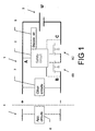
- FIG. 1 is a block diagram of a device implementing the invention and connected to an apparatus.
- a battery pack for portable devices usually comprises electronic circuits in addition to the battery cell itself.
- Figure 1 illustrates a block diagram of a battery pack 1 suitable for connection to an apparatus 4. The poles of the battery pack 1 are to the right of the dashed line, while the apparatus 4 with its circuits 8 are to the left.
- the battery pack comprises a safety circuit 2.
- Lithium-Ion/Lithium-Polymer cells are sensitive for overcharging and also should not be overdischarged.
- the purpose of the safety circuit 2 is to protect the battery cell and to some extent an apparatus connected to the battery pack.
- the safety circuit 2 comprises voltage and current detectors and could also incorporate circuits for calculating the remaining capacity/energy content of the battery.
- the safety circuit detects over/undervoltage between the voltage points A-C, detects high current between points B-C and detects short circuits between points A-B.
- the safety circuit 2 usually comprises dual MOSFET transistors 6B and 6C to switch off the battery cell 3 from the apparatus 4.
- Overvoltage is when the detected voltage U increases over a predetermined overcharge (OCH) limit over which the battery cell could be damaged, that is U > U OCH , the value U OCH being set by the manufacturer.
- Undervoltage is set at another voltage U z (Z for zero capacity left) corresponding to when the battery cell has an output voltage U which is just able to power the apparatus but if more capacity is drawn from the battery cell the voltage will be too low.
- U ⁇ U z could for instance be at approximately 3 V or 70% of the maximum voltage in a mobile telephone.
- the remaining capacity E is measured instead of the voltage.
- the safety circuit 2 switches off the apparatus when E ⁇ E z .
- E z could for instance be at approximately 20 % of the total maximum capacity of the battery cell.
- the safety circuit 2 consumes power from the battery cell. Even if the current consumption is very low e.g. in the same order as the internal discharge current of the battery cell, this has an impact on the shelf life of the battery pack.
- the present inventors have realised that it would be suitable to switch off also the safety circuit when the battery pack is stored.
- the other circuits 7, such as communication ASIC etc, are not harmed by being cut off from the battery cell.
- the MOSFET transistors 6B and 6C of the safety circuit 2 are used for switching off the current from the battery cell 3.
- a disconnection control means 5 is connected to or integrated with the safety circuit 2.
- the disconnection control means controls the switchable element of the safety circuit to switch off the battery cell.
- the disconnection control means basically has three operation modes or functions: a manual function in which the disconnection control means 5 is simply receiving a command to switch off, a first automatic mode in which the time from disconnection of the battery is measured and controlling when the switch off is made, and a second automatic mode when a battery parameter is detected which triggers the switch off.
- the disconnection control means receives a signal commanding the disconnection control means to switch off the battery cell 3 by means of the switchable elements 6B and 6B.
- This is useful for example when performing a final check in a battery pack checking unit during manufacturing of the battery pack.
- the apparatus with which the battery pack normally is used may be provided with a feature enabling switching off of the battery. This is useful when the user intends to remove the battery pack for storing or when he knows that he will not be using the apparatus for some time.
- the battery preserving device is also provided with automatic modes which do not rely on the user to activate the battery preserving function.
- the disconnection control means 5 comprises an activity detection means, which detects when the battery pack is not connected to the apparatus 4.
- the activity detection means could detect an activity signal from the apparatus.
- there is a timer circuit measuring the time t elapsed since the battery was disconnected from the apparatus. When the elapsed time t is greater than a limit t max the disconnection is performed- t max is suitably predefined based upon the application, and could for example be one hour, 24 hours, a week etc.
- the disconnection means also comprises a detection means adapted to sense a parameter of the battery cell 3, for instance the voltage U or the remaining capacity E (measured e.g. in mAh). Then the disconnection is effected when the detected voltage U of the battery cell decreases below a predetermined limit U preserve .
- the remaining capacity E of the battery cell is measured, and the disconnection is performed when the remaining capacity E falls below a predetermined limit E preserve .
- U preserve could for instance be at approximately 70 - 80% of the maximum voltage of the battery cell when fully charged.
- E preserve could for instance be at approximately 10 - 40% of the maximum capacity of the battery cell when fully charged.
- the disconnection control means 5 is adapted to switch off the current consumption when a measured parameter, the voltage U or capacity E, falls below a predetermined limit U low /E low .
- This operation mode could operate independently of whether the battery pack is disconnected or not from the apparatus. However, normally in this case the battery pack is connected to the apparatus 4 and the limits U low and E low , respectively, are set lower than the limit U z /E z at which the safety switch disconnects the apparatus. For instance if U z is set at 70% of the total maximum voltage the limit U low is set at 60% of the total maximum voltage. For instance if E z is set at 20% of the total maximum capacity the limit E low is set at 10 - 20% of the total maximum capacity.
- U low /E low , U z /E z and U preserve /E preserve are used together U low /E low ⁇ U z /E z ⁇ U preserve /E preserve.
- the present invention may be implemented in a battery preserving device as such, together with or separate from a conventional safety circuit.
- the invention also involves a battery pack incorporating such a battery preserving device.
- the invention also involves an apparatus adapted to co-operate with such a battery preserving device e.g. a mobile telephone or a battery pack checking unit.
- a battery preserving device e.g. a mobile telephone or a battery pack checking unit.
- the apparatus is adapted to send a disconnection signal to the disconnection control means in order to command the switchable element to disconnect all circuits including the safety circuit.
- the so called battery removal detection signal could be used to switch off the battery pack.
- the user or operator may command a disconnection by entering a command on the apparatus. This could for example be when the user intends to remove the battery pack for storing or when he knows that he will not be using the apparatus for some time, or when performing a final check of the battery pack, as mentioned above.
- the apparatus should be able to switch the battery pack back on again, if the disconnection has been activated. Then the apparatus sends a start signal to the disconnection control means in order to command the switchable element to connect all circuits including the safety circuit.
- the start signal may be a start sequence from an apparatus connected to the battery pack.
- the apparatus is adapted to send the start signal when the apparatus is switched on. This presupposes that the apparatus has some energy stored or is connected to another power source so that it is able to be switched on (despite being disconnected from the battery cell).
- the apparatus may also be adapted to send the start signal when the apparatus is connected to a battery charging unit. For example, when a battery cell has low voltage, the user may want to charge it in the apparatus, and the disconnection must be deactivated.
Landscapes
- Engineering & Computer Science (AREA)
- Power Engineering (AREA)
- Charge And Discharge Circuits For Batteries Or The Like (AREA)
Priority Applications (1)
| Application Number | Priority Date | Filing Date | Title |
|---|---|---|---|
| EP04101790A EP1598914A1 (de) | 2004-04-28 | 2004-04-28 | Batteriesparungsvorrichtung und eine solche Vorrichtung aufweisendes Batteriepack |
Applications Claiming Priority (1)
| Application Number | Priority Date | Filing Date | Title |
|---|---|---|---|
| EP04101790A EP1598914A1 (de) | 2004-04-28 | 2004-04-28 | Batteriesparungsvorrichtung und eine solche Vorrichtung aufweisendes Batteriepack |
Publications (1)
| Publication Number | Publication Date |
|---|---|
| EP1598914A1 true EP1598914A1 (de) | 2005-11-23 |
Family
ID=34929031
Family Applications (1)
| Application Number | Title | Priority Date | Filing Date |
|---|---|---|---|
| EP04101790A Withdrawn EP1598914A1 (de) | 2004-04-28 | 2004-04-28 | Batteriesparungsvorrichtung und eine solche Vorrichtung aufweisendes Batteriepack |
Country Status (1)
| Country | Link |
|---|---|
| EP (1) | EP1598914A1 (de) |
Cited By (2)
| Publication number | Priority date | Publication date | Assignee | Title |
|---|---|---|---|---|
| EP3650177A1 (de) * | 2018-10-01 | 2020-05-13 | Makita Corporation | Akkupack und system |
| US11482764B2 (en) | 2018-10-01 | 2022-10-25 | Makita Corporation | Technique of determining first, second, and third potentials at communication terminal of battery pack |
Citations (4)
| Publication number | Priority date | Publication date | Assignee | Title |
|---|---|---|---|---|
| US6160381A (en) * | 1998-05-21 | 2000-12-12 | Qualcomm Inc. | Battery pack protection circuit and battery pack including a protection circuit |
| US6208117B1 (en) * | 1999-07-30 | 2001-03-27 | Fujitsu Limited | Battery pack and electronic apparatus using the same |
| US6271605B1 (en) * | 1999-05-04 | 2001-08-07 | Research In Motion Limited | Battery disconnect system |
| JP2003282159A (ja) * | 2002-03-26 | 2003-10-03 | Shin Kobe Electric Mach Co Ltd | 電池制御システム |
-
2004
- 2004-04-28 EP EP04101790A patent/EP1598914A1/de not_active Withdrawn
Patent Citations (4)
| Publication number | Priority date | Publication date | Assignee | Title |
|---|---|---|---|---|
| US6160381A (en) * | 1998-05-21 | 2000-12-12 | Qualcomm Inc. | Battery pack protection circuit and battery pack including a protection circuit |
| US6271605B1 (en) * | 1999-05-04 | 2001-08-07 | Research In Motion Limited | Battery disconnect system |
| US6208117B1 (en) * | 1999-07-30 | 2001-03-27 | Fujitsu Limited | Battery pack and electronic apparatus using the same |
| JP2003282159A (ja) * | 2002-03-26 | 2003-10-03 | Shin Kobe Electric Mach Co Ltd | 電池制御システム |
Non-Patent Citations (2)
| Title |
|---|
| PATENT ABSTRACTS OF JAPAN vol. 2003, no. 12 5 December 2003 (2003-12-05) * |
| STOCKSTAD T ET AL: "A micropower safety IC for rechargeable lithium batteries", CUSTOM INTEGRATED CIRCUITS CONFERENCE, 1996., PROCEEDINGS OF THE IEEE 1996 SAN DIEGO, CA, USA 5-8 MAY 1996, NEW YORK, NY, USA,IEEE, US, 5 May 1996 (1996-05-05), pages 127 - 130, XP010167430, ISBN: 0-7803-3117-6 * |
Cited By (2)
| Publication number | Priority date | Publication date | Assignee | Title |
|---|---|---|---|---|
| EP3650177A1 (de) * | 2018-10-01 | 2020-05-13 | Makita Corporation | Akkupack und system |
| US11482764B2 (en) | 2018-10-01 | 2022-10-25 | Makita Corporation | Technique of determining first, second, and third potentials at communication terminal of battery pack |
Similar Documents
| Publication | Publication Date | Title |
|---|---|---|
| US6118250A (en) | Power supply assembly for hand-held communications device | |
| EP0657982B1 (de) | Batteriesystem eines tragbaren elektrischen Geräts | |
| US6288521B1 (en) | Intelligent power management for rechargeable batteries | |
| US5963015A (en) | External battery charger for use with a battery powered electronic device and an extra battery | |
| US7531986B2 (en) | Power supply for battery powered devices | |
| US7847514B2 (en) | Apparatus and method for the power management of operatively connected batteries respectively on a handheld electronic device and a holder for the handheld electronic device | |
| US6246890B1 (en) | Portable telephone with built-in charger | |
| JP2001190032A (ja) | 電力供給制御回路及び電力供給制御方法 | |
| JP3174482U (ja) | エネルギー装置 | |
| EP1096638A1 (de) | Elektronische vorrichtung und verfahren zur steuerung von elektronischen vorrichtungen | |
| US7671560B2 (en) | Method and apparatus for handling deeply discharged batteries in a mobile station | |
| JP2002359009A (ja) | 充電器 | |
| JP3778709B2 (ja) | 電池パック | |
| JP2002208443A (ja) | パック電池 | |
| JP2000116011A (ja) | 二次電池保護回路 | |
| JP2006148997A (ja) | 充電装置及び充電方法 | |
| JP3894377B2 (ja) | バツテリパツク及びバツテリパツクの制御方法 | |
| JP2002300732A (ja) | 二次電池装置 | |
| WO2002087055A1 (en) | Electronic apparatus having charging function | |
| KR100798884B1 (ko) | 배터리 충전 장치 및 방법 | |
| JPH07326389A (ja) | 無線通信装置 | |
| CN212969124U (zh) | 一种基于外置电池的双电池电子设备 | |
| JP2002320333A (ja) | 充電機能付き電子機器 | |
| CA2609864A1 (en) | Electronic device, including handheld electronic device, with dual battery configuration and associated method | |
| JPH09320641A (ja) | 充電式電池パック |
Legal Events
| Date | Code | Title | Description |
|---|---|---|---|
| PUAI | Public reference made under article 153(3) epc to a published international application that has entered the european phase |
Free format text: ORIGINAL CODE: 0009012 |
|
| AK | Designated contracting states |
Kind code of ref document: A1 Designated state(s): AT BE BG CH CY CZ DE DK EE ES FI FR GB GR HU IE IT LI LU MC NL PL PT RO SE SI SK TR |
|
| AX | Request for extension of the european patent |
Extension state: AL HR LT LV MK |
|
| AKX | Designation fees paid | ||
| REG | Reference to a national code |
Ref country code: DE Ref legal event code: 8566 |
|
| STAA | Information on the status of an ep patent application or granted ep patent |
Free format text: STATUS: THE APPLICATION IS DEEMED TO BE WITHDRAWN |
|
| 18D | Application deemed to be withdrawn |
Effective date: 20060524 |