EP1598924A2 - Ondueur sans harmoniques - Google Patents
Ondueur sans harmoniques Download PDFInfo
- Publication number
- EP1598924A2 EP1598924A2 EP05106885A EP05106885A EP1598924A2 EP 1598924 A2 EP1598924 A2 EP 1598924A2 EP 05106885 A EP05106885 A EP 05106885A EP 05106885 A EP05106885 A EP 05106885A EP 1598924 A2 EP1598924 A2 EP 1598924A2
- Authority
- EP
- European Patent Office
- Prior art keywords
- inverter
- output
- harmonics
- current
- choke
- Prior art date
- Legal status (The legal status is an assumption and is not a legal conclusion. Google has not performed a legal analysis and makes no representation as to the accuracy of the status listed.)
- Granted
Links
Images

Classifications
-
- H—ELECTRICITY
- H02—GENERATION; CONVERSION OR DISTRIBUTION OF ELECTRIC POWER
- H02M—APPARATUS FOR CONVERSION BETWEEN AC AND AC, BETWEEN AC AND DC, OR BETWEEN DC AND DC, AND FOR USE WITH MAINS OR SIMILAR POWER SUPPLY SYSTEMS; CONVERSION OF DC OR AC INPUT POWER INTO SURGE OUTPUT POWER; CONTROL OR REGULATION THEREOF
- H02M1/00—Details of apparatus for conversion
- H02M1/12—Arrangements for reducing harmonics from AC input or output
- H02M1/126—Arrangements for reducing harmonics from AC input or output using passive filters
-
- H—ELECTRICITY
- H02—GENERATION; CONVERSION OR DISTRIBUTION OF ELECTRIC POWER
- H02M—APPARATUS FOR CONVERSION BETWEEN AC AND AC, BETWEEN AC AND DC, OR BETWEEN DC AND DC, AND FOR USE WITH MAINS OR SIMILAR POWER SUPPLY SYSTEMS; CONVERSION OF DC OR AC INPUT POWER INTO SURGE OUTPUT POWER; CONTROL OR REGULATION THEREOF
- H02M1/00—Details of apparatus for conversion
- H02M1/12—Arrangements for reducing harmonics from AC input or output
- H02M1/123—Suppression of common mode voltage or current
Definitions
- the invention relates to an inverter or an output filter for inverters.
- the output current of an inverter for higher power points in usually a whole bunch of current harmonics up. These harmonics are annoying and especially if greater power over inverter be fed into a network, they occur unpleasantly.
- FIG. 1 shows an inverter with an output choke and a capacitor filter network shown, the above-described technical disadvantage of inverters significantly reduced and the power quality significantly improved.
- the power switches T1 to T6 and the diodes connected in parallel therewith be switched by means of a pulse width modulation of the circuit breaker, that at the output of the inverter three sinusoidal output currents phases U, V, W arise.
- the shape of the output current is determined by Switching the individual switches T1-T6 on or off approximates to a sinusoidal oscillation. However, due to the inevitable deviations from the Setpoint the mentioned harmonics.
- FIG. 1 shows the circuit diagram of a known inverter, which by the Anti-parallel connection of the power switches T1 to T6, each with a diode D1-D6 allows a four-quadrant operation and thus very versatile as a circuit can be used.
- Tn 1, 3, 5
- the circuit breakers is a DC voltage intermediate circuit with two series-connected electrolytic capacitors C4 and C5 for feeding the DC voltage + Ud and - Ud upstream.
- the inverter points an output choke LA (LAU, LAV, LAW) and a downstream Filter consisting of three capacitors C6, C7, C8, which between each Phases are arranged on.
- LA LAU, LAV, LAW
- C6, C7, C8 which between each Phases are arranged on.
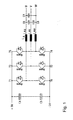
- FIG. 2 shows the circuit diagram of an inverter according to the invention. This has as the known inverter DC voltage intermediate circuit breaker T1 - T6 and parallel connected diodes D1 - D6 and a Output choke LA on.
- the inverter according to the invention generates unbalanced harmonics.
- an additional winding L4 (additional leg) is provided. 1
- This fourth leg L4 transmits the unbalanced magnetic fluxes that out the unbalanced harmonics arise.
- the harmonics will be over three oscillating circuits LC or three L-C-links, consisting of the inductivities L1 to L3 and the capacitors C1 to C3 and a common Star point. Symmetric harmonics are with these resonant circuits LC, as far as they are still available, directly compensated.
- Unbalanced harmonics L4 ( ⁇ I ⁇ 0) will be over the neutral point of the winding of the fourth Supplied to Schenkel's L4.
- This fourth winding L4 is connected to the minus rail of the DC DC link connected.
- the sum of the unbalanced ones Harmonics is thus tapped at the star point of the filter capacitors and via the winding on the fourth leg L4 in the DC intermediate circuit coupled. This results in a closed harmonic current circuit for the unbalanced harmonics.
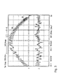
- FIG. 3 shows a measuring diagram of the inverter according to FIG. 2.
- the upper curve shows the positive sine half-wave of the current at the inverter output. In this case, the hysteresis of the current is constant and the switching frequency variable.
- the lower curve shows the sum of the harmonics of the three Output phases of the inverter, which over the fourth leg in the Return DC voltage intermediate circuit.
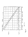
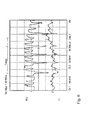
- Figure 4 shows again a part of the output current of the inverter of Phase 1 in higher resolution. Here are clearly the triangular harmonics of the output current IWR LA.
- Figure 5 shows the result of the separation of the harmonics from the main stream (Fundamental 50 Hz).
- the uppermost curve shows the output current without harmonics. This very good result is only with the invention Harmonic circuit possible.
- the middle curve in FIG. 5 shows the inverter current IWR LA and the lower curve in Figure 5 shows again the associated harmonic current.
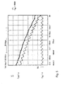
- FIG. 6 shows the sum of the three harmonic currents I21, I22 and I23.
- This current which contains almost all the harmonics of the three phases, is now used again to increase the effect of the output inductor LA.
- This throttle consists, as already described, of the three main legs LA1, LA2, LA3 for the three main output windings and a fourth small daughter leg, which is intended only for the harmonics.
- This fourth Thigh leads only the magnetic fluxes, which is the sum of the harmonics correspond.
- the corresponding amplitude of this summation current of the harmonics is shown in Figure 6, lower curve.
- the upper curve shows the corresponding voltage curve for this purpose. To achieve this is an iron cross section of about 20% of the main leg sufficient for the fourth leg. Of the fourth leg increases but the acting output inductance LA by about 5-20%. This results in a smaller size of the output inductor LA and a better one Efficiency.
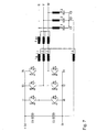
- FIG. 7 shows a development of the inverter according to the invention.
- the Output choke is in this case constructed in two parts and consists of a four-limb throttle and a series-connected compensated three-phase reactor LA2.
- For unbalanced harmonic currents can be advantageous current-compensated Chokes are used. Since the sum of the mains current (three-phase current) is zero, the throttle will not start with the very high fundamental frequencies loaded (premagnetized). Thus, with little effort a high Inductance are built.
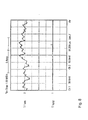
- FIG. 8 upper curve, shows the sum of the three output currents at the inverter output in front of the filter. The maximum amplitude is only 10% of the Peak value of a phase current. The lower curve shows the sum of the output currents after the filter. As you can see, this output current is excellent high quality and does not couple any negative harmonics into it Network.
- the DC intermediate circuit is connected to the closed harmonic circuit stabilized at the same time.
- the neutral point of the three capacitors has a dormant, in principle the same potential as earth. Because this point is static connected via the inductor to the intermediate circuit, flows over this Equalizing current when the potential of the DC link changes. Jumping Potentials are for generators that feed into the DC link, detrimental, because by voltage changes (dU / dt) a capacitive current would flow through the insulation and cause long-term insulation damage.
- An inverter according to the invention is preferred in an electrical energy generating system, such as a wind turbine used.
- Such electrical energy generating systems then provide the network with a Electricity of the highest quality, which also has the consequence that the respective network operator Fewer measures must be taken to ensure electricity quality.
Landscapes
- Engineering & Computer Science (AREA)
- Power Engineering (AREA)
- Inverter Devices (AREA)
- Power Conversion In General (AREA)
- Supply And Distribution Of Alternating Current (AREA)
Priority Applications (1)
| Application Number | Priority Date | Filing Date | Title |
|---|---|---|---|
| CY20151100514T CY1116403T1 (el) | 1999-02-25 | 2015-06-12 | Αναστροφεας εναλλασσομενου ρευματος χωρις αρμονικες συνιστωσες |
Applications Claiming Priority (3)
| Application Number | Priority Date | Filing Date | Title |
|---|---|---|---|
| DE19908124 | 1999-02-25 | ||
| DE19908124A DE19908124C2 (de) | 1999-02-25 | 1999-02-25 | Wechselrichter ohne Oberschwingungen |
| EP99950783A EP1078445B1 (fr) | 1999-02-25 | 1999-10-27 | Onduleur |
Related Parent Applications (1)
| Application Number | Title | Priority Date | Filing Date |
|---|---|---|---|
| EP99950783A Division EP1078445B1 (fr) | 1999-02-25 | 1999-10-27 | Onduleur |
Publications (3)
| Publication Number | Publication Date |
|---|---|
| EP1598924A2 true EP1598924A2 (fr) | 2005-11-23 |
| EP1598924A3 EP1598924A3 (fr) | 2008-04-09 |
| EP1598924B1 EP1598924B1 (fr) | 2015-04-22 |
Family
ID=7898814
Family Applications (2)
| Application Number | Title | Priority Date | Filing Date |
|---|---|---|---|
| EP20050106885 Expired - Lifetime EP1598924B1 (fr) | 1999-02-25 | 1999-10-27 | Ondueur sans harmoniques |
| EP99950783A Expired - Lifetime EP1078445B1 (fr) | 1999-02-25 | 1999-10-27 | Onduleur |
Family Applications After (1)
| Application Number | Title | Priority Date | Filing Date |
|---|---|---|---|
| EP99950783A Expired - Lifetime EP1078445B1 (fr) | 1999-02-25 | 1999-10-27 | Onduleur |
Country Status (16)
| Country | Link |
|---|---|
| US (1) | US6452819B1 (fr) |
| EP (2) | EP1598924B1 (fr) |
| JP (1) | JP3571654B2 (fr) |
| AR (1) | AR022774A1 (fr) |
| AT (1) | ATE315843T1 (fr) |
| AU (1) | AU758259B2 (fr) |
| BR (1) | BR9909183A (fr) |
| CA (1) | CA2310391C (fr) |
| CY (2) | CY1105730T1 (fr) |
| DE (2) | DE19908124C2 (fr) |
| DK (2) | DK1598924T3 (fr) |
| ES (2) | ES2541435T3 (fr) |
| NZ (1) | NZ504757A (fr) |
| PT (1) | PT1598924E (fr) |
| TR (1) | TR200001595T1 (fr) |
| WO (1) | WO2000051225A1 (fr) |
Cited By (3)
| Publication number | Priority date | Publication date | Assignee | Title |
|---|---|---|---|---|
| DE202011101851U1 (de) | 2011-05-18 | 2012-08-20 | Block Transformatoren-Elektronik Gmbh | Filterschaltung |
| DE102013208911A1 (de) * | 2013-05-14 | 2014-11-20 | Schmidbauer Transformatoren und Gerätebau GmbH | Mehrphasige Drossel mit integriertem Störungsunterdrückungstransformator |
| DE102015104660A1 (de) | 2015-03-26 | 2016-09-29 | Block Transformatoren-Elektronik Gmbh | Drosselanordnung |
Families Citing this family (17)
| Publication number | Priority date | Publication date | Assignee | Title |
|---|---|---|---|---|
| DE10034054A1 (de) * | 2000-07-13 | 2002-04-04 | Epcos Ag | Netzfilter |
| DE20222013U1 (de) * | 2002-06-07 | 2010-11-04 | Epcos Ag | Stromkompensierte Drossel und Schaltungsanordnung mit der stromkompensierten Drossel |
| FI116178B (fi) * | 2002-08-22 | 2005-09-30 | Abb Oy | Vaihtosuuntaajan lähtökuristinsovitelma |
| US6816394B2 (en) * | 2003-03-05 | 2004-11-09 | Natus Technology Corp. | Approximated sinusoidal waveform inverter |
| ATE349102T1 (de) * | 2004-09-09 | 2007-01-15 | Abb Oy | Steuerung ohne geschwindigkeitsfühler einer induktionsmaschine unter verwendung eines pbm- wechselrichters mit lc ausgangsfilter |
| JP5422178B2 (ja) * | 2008-11-12 | 2014-02-19 | 株式会社東芝 | 系統連系インバータ |
| FR2945166B1 (fr) * | 2009-04-29 | 2014-03-07 | Converteam Technology Ltd | Filtre passif et systeme d'alimentation d'un moteur electrique comprenant un tel filtre |
| TWI454028B (zh) * | 2010-01-13 | 2014-09-21 | Toshiba Kk | System interconnection converter |
| US8618694B2 (en) * | 2010-06-30 | 2013-12-31 | Vestas Wind Systems A/S | System, method, and computer program product for utilizing a wind park as a variable power system stabilizer |
| DE102010040835A1 (de) * | 2010-09-15 | 2012-03-15 | Robert Bosch Gmbh | Filter für eine Dreiphasenwechselspannung und einen Dreiphasenwechselstrom und Verfahren zum Filtern einer Dreiphasenwechselspannung und eines Dreiphasenwechselstroms |
| US20130039105A1 (en) * | 2011-08-09 | 2013-02-14 | Hamilton Sundstrand Corporation | Filter circuit for a multi-phase ac input |
| DE102012207557A1 (de) | 2012-05-07 | 2013-11-07 | Wobben Properties Gmbh | Dreiphasige Drossel |
| DE102014205845B4 (de) | 2013-03-28 | 2025-06-12 | Robert Bosch Gmbh | Ansteuervorrichtung zur Ansteuerung eines Elektromotors und Verfahren zur Kompensation eines Störsignals in einer Ansteuerschaltung für einen Elektromotor |
| US9800133B2 (en) * | 2016-03-22 | 2017-10-24 | Infineon Technologies Ag | Active common mode cancellation |
| DE102016107295A1 (de) * | 2016-04-20 | 2017-10-26 | Wobben Properties Gmbh | Drehstromdrosselspule |
| DE102017109728A1 (de) | 2017-05-05 | 2018-11-08 | Wobben Properties Gmbh | Windenergieanlage mit überlastfähigem Umrichtersystem |
| US12282045B2 (en) | 2022-12-02 | 2025-04-22 | Infineon Technologies Ag | Common mode evaluation in a differential galvanic isolation signal transmission circuit |
Family Cites Families (12)
| Publication number | Priority date | Publication date | Assignee | Title |
|---|---|---|---|---|
| DE2446635A1 (de) * | 1974-09-30 | 1976-04-08 | Siemens Ag | Wechselrichteranordnung mit zwei dreiphasigen steuerbaren wechselrichtern |
| JPS6130917A (ja) * | 1984-07-19 | 1986-02-13 | 富士電気化学株式会社 | 3相4線式用ノイズフイルタ |
| US5499178A (en) * | 1991-12-16 | 1996-03-12 | Regents Of The University Of Minnesota | System for reducing harmonics by harmonic current injection |
| US5377092A (en) | 1992-11-16 | 1994-12-27 | International Power Machines | Method and apparatus for harmonic distortion correction |
| WO1994018683A1 (fr) * | 1993-02-12 | 1994-08-18 | Regents Of The University Of Minnesota | Systeme d'attenuation des harmoniques par injection de courant harmonique |
| US5568371A (en) * | 1994-09-29 | 1996-10-22 | Texas A&M University System | Active harmonic power filter apparatus and method |
| US5513090A (en) | 1994-11-15 | 1996-04-30 | Electric Power Research Institute, Inc. | Hybrid series active, parallel passive, power line conditioner for harmonic isolation between a supply and a load |
| DE29506951U1 (de) | 1995-04-25 | 1995-06-22 | Siemens AG, 80333 München | Schaltungsanordnung zur Entstörung |
| US5661390A (en) * | 1995-06-23 | 1997-08-26 | Electric Power Research Institute, Inc. | Inverter-fed motor drive with EMI suppression |
| US5646498A (en) * | 1995-08-07 | 1997-07-08 | Eaton Corporation | Conducted emission radiation suppression in inverter drives |
| DE19637290A1 (de) * | 1996-09-13 | 1998-03-19 | Asea Brown Boveri | Stromrichterschaltungsanordnung mit lastseitigem Filter |
| JP2863833B2 (ja) * | 1996-09-18 | 1999-03-03 | 岡山大学長 | アクティブコモンモードキャンセラ |
-
1999
- 1999-02-25 DE DE19908124A patent/DE19908124C2/de not_active Expired - Lifetime
- 1999-10-27 ES ES05106885.6T patent/ES2541435T3/es not_active Expired - Lifetime
- 1999-10-27 DK DK05106885.6T patent/DK1598924T3/en active
- 1999-10-27 EP EP20050106885 patent/EP1598924B1/fr not_active Expired - Lifetime
- 1999-10-27 TR TR2000/01595T patent/TR200001595T1/xx unknown
- 1999-10-27 NZ NZ504757A patent/NZ504757A/xx not_active IP Right Cessation
- 1999-10-27 BR BR9909183-6A patent/BR9909183A/pt not_active Application Discontinuation
- 1999-10-27 DK DK99950783T patent/DK1078445T3/da active
- 1999-10-27 EP EP99950783A patent/EP1078445B1/fr not_active Expired - Lifetime
- 1999-10-27 US US09/601,850 patent/US6452819B1/en not_active Expired - Lifetime
- 1999-10-27 DE DE59913048T patent/DE59913048D1/de not_active Expired - Lifetime
- 1999-10-27 AU AU63427/99A patent/AU758259B2/en not_active Ceased
- 1999-10-27 PT PT51068856T patent/PT1598924E/pt unknown
- 1999-10-27 AT AT99950783T patent/ATE315843T1/de active
- 1999-10-27 ES ES99950783T patent/ES2253918T3/es not_active Expired - Lifetime
- 1999-10-27 CA CA002310391A patent/CA2310391C/fr not_active Expired - Lifetime
- 1999-10-27 JP JP2000601728A patent/JP3571654B2/ja not_active Expired - Lifetime
- 1999-10-27 WO PCT/EP1999/008118 patent/WO2000051225A1/fr not_active Ceased
-
2000
- 2000-02-25 AR ARP000100849A patent/AR022774A1/es active IP Right Grant
-
2006
- 2006-03-28 CY CY20061100429T patent/CY1105730T1/el unknown
-
2015
- 2015-06-12 CY CY20151100514T patent/CY1116403T1/el unknown
Cited By (4)
| Publication number | Priority date | Publication date | Assignee | Title |
|---|---|---|---|---|
| DE202011101851U1 (de) | 2011-05-18 | 2012-08-20 | Block Transformatoren-Elektronik Gmbh | Filterschaltung |
| DE102011102134A1 (de) | 2011-05-18 | 2012-11-22 | Block Transformatoren-Elektronik Gmbh | Filterschaltung |
| DE102013208911A1 (de) * | 2013-05-14 | 2014-11-20 | Schmidbauer Transformatoren und Gerätebau GmbH | Mehrphasige Drossel mit integriertem Störungsunterdrückungstransformator |
| DE102015104660A1 (de) | 2015-03-26 | 2016-09-29 | Block Transformatoren-Elektronik Gmbh | Drosselanordnung |
Also Published As
| Publication number | Publication date |
|---|---|
| DE59913048D1 (de) | 2006-04-06 |
| NZ504757A (en) | 2003-03-28 |
| CY1116403T1 (el) | 2017-02-08 |
| EP1078445B1 (fr) | 2006-01-11 |
| PT1598924E (pt) | 2015-09-14 |
| US6452819B1 (en) | 2002-09-17 |
| EP1598924A3 (fr) | 2008-04-09 |
| DK1078445T3 (da) | 2006-05-22 |
| JP3571654B2 (ja) | 2004-09-29 |
| ES2541435T3 (es) | 2015-07-20 |
| TR200001595T1 (tr) | 2001-01-22 |
| EP1078445A1 (fr) | 2001-02-28 |
| BR9909183A (pt) | 2000-12-05 |
| AU6342799A (en) | 2000-09-14 |
| WO2000051225A1 (fr) | 2000-08-31 |
| ES2253918T3 (es) | 2006-06-01 |
| DK1598924T3 (en) | 2015-06-29 |
| DE19908124A1 (de) | 2000-09-07 |
| AR022774A1 (es) | 2002-09-04 |
| ATE315843T1 (de) | 2006-02-15 |
| HK1034818A1 (en) | 2001-11-02 |
| EP1598924B1 (fr) | 2015-04-22 |
| CA2310391A1 (fr) | 2000-08-25 |
| DE19908124C2 (de) | 2003-04-30 |
| CA2310391C (fr) | 2003-10-14 |
| AU758259B2 (en) | 2003-03-20 |
| JP2002538752A (ja) | 2002-11-12 |
| CY1105730T1 (el) | 2010-12-22 |
Similar Documents
| Publication | Publication Date | Title |
|---|---|---|
| DE19908124C2 (de) | Wechselrichter ohne Oberschwingungen | |
| EP1118151B1 (fr) | Installation de transport d'energie electrique | |
| DE3854586T2 (de) | Leistungswandlungseinrichtung. | |
| DE10114075B4 (de) | Stromrichterschaltungsanordnung für Generatoren mit dynamisch veränderlicher Leistungsabgabe | |
| AT506816B9 (de) | Vlf-prüfgenerator | |
| DE69005647T2 (de) | System zum ableiten elektrischer energie von einer hochspannungs-gleichstrom-übertragungsleitung. | |
| EP2815497B1 (fr) | Dispositif d'alimentation réseau, système d'alimentation en énergie et procédé de fonctionnement d'un disposif d'alimentation réseau | |
| DE4232356A1 (de) | Stromversorgungseinrichtung mit mindestens zwei Stromrichtern, z.B. Windkraftanlage, Photovoltaikanlage, Batteriespeicher sowie Kombinationen hiervon | |
| EP2107672A1 (fr) | Onduleur triphasé sans connexion entre le conducteur de neutre du réseau et le point milieu du circuit intermédiaire | |
| DE1488096B2 (de) | Wechselrichterschaltung | |
| WO2011154506A2 (fr) | Topologie de circuit pour connexion de phase d'un onduleur | |
| DE102019130838A1 (de) | Eine Filteranordnung | |
| EP2421135B1 (fr) | Onduleur sans transformateur avec convertisseur abaisseur | |
| DE2825240C2 (de) | Rundsteueranlage | |
| DE102019130839A1 (de) | Eine Induktorbaugruppe | |
| DE2843528A1 (de) | Leistungswechselrichter | |
| DE3784899T2 (de) | Dreiphasentransformator fuer zykloumsetzer. | |
| DE102013208911A1 (de) | Mehrphasige Drossel mit integriertem Störungsunterdrückungstransformator | |
| EP2281206B1 (fr) | Générateur de très basse fréquence pour essais | |
| EP3531547B1 (fr) | Circuit de commande permettant de coupler une machine synchrone avec un réseau de tension et procédé de fonctionnement dudit circuit | |
| DE3014352A1 (de) | Schaltungsanordnung fuer ein- oder mehrphasige elektrische maschinen | |
| DE1906432A1 (de) | Umwandler fuer elektrische Leistung | |
| DE112015000929T5 (de) | Einrichtung und Verfahren zum Reduzieren von Oberschwingungen | |
| DE102013200520A1 (de) | Wechselrichteranordnung und Verfahren zum Erzeugen eines elektrischen Wechselstroms | |
| DE1463259C3 (de) | Stromversorgungseinrichtung für Wechselstrom konstanter Frequenz mit einem bei variabler Drehzahl antreibbaren Wechselstromgenerator |
Legal Events
| Date | Code | Title | Description |
|---|---|---|---|
| PUAI | Public reference made under article 153(3) epc to a published international application that has entered the european phase |
Free format text: ORIGINAL CODE: 0009012 |
|
| AC | Divisional application: reference to earlier application |
Ref document number: 1078445 Country of ref document: EP Kind code of ref document: P |
|
| AK | Designated contracting states |
Kind code of ref document: A2 Designated state(s): AT BE CH CY DE DK ES FI FR GB GR IE IT LI LU MC NL PT SE |
|
| PUAL | Search report despatched |
Free format text: ORIGINAL CODE: 0009013 |
|
| AK | Designated contracting states |
Kind code of ref document: A3 Designated state(s): AT BE CH CY DE DK ES FI FR GB GR IE IT LI LU MC NL PT SE |
|
| 17P | Request for examination filed |
Effective date: 20081009 |
|
| AKX | Designation fees paid |
Designated state(s): AT BE CH CY DE DK ES FI FR GB GR IE IT LI LU MC NL PT SE |
|
| 17Q | First examination report despatched |
Effective date: 20081125 |
|
| GRAP | Despatch of communication of intention to grant a patent |
Free format text: ORIGINAL CODE: EPIDOSNIGR1 |
|
| INTG | Intention to grant announced |
Effective date: 20141125 |
|
| RAP1 | Party data changed (applicant data changed or rights of an application transferred) |
Owner name: WOBBEN PROPERTIES GMBH |
|
| RIN1 | Information on inventor provided before grant (corrected) |
Inventor name: WOBBEN, ALOYS |
|
| GRAS | Grant fee paid |
Free format text: ORIGINAL CODE: EPIDOSNIGR3 |
|
| GRAA | (expected) grant |
Free format text: ORIGINAL CODE: 0009210 |
|
| AC | Divisional application: reference to earlier application |
Ref document number: 1078445 Country of ref document: EP Kind code of ref document: P |
|
| AK | Designated contracting states |
Kind code of ref document: B1 Designated state(s): AT BE CH CY DE DK ES FI FR GB GR IE IT LI LU MC NL PT SE |
|
| REG | Reference to a national code |
Ref country code: GB Ref legal event code: FG4D Free format text: NOT ENGLISH |
|
| REG | Reference to a national code |
Ref country code: CH Ref legal event code: EP Ref country code: CH Ref legal event code: NV Representative=s name: WEINMANN ZIMMERLI, CH |
|
| REG | Reference to a national code |
Ref country code: AT Ref legal event code: REF Ref document number: 723767 Country of ref document: AT Kind code of ref document: T Effective date: 20150515 |
|
| REG | Reference to a national code |
Ref country code: IE Ref legal event code: FG4D Free format text: LANGUAGE OF EP DOCUMENT: GERMAN |
|
| REG | Reference to a national code |
Ref country code: DE Ref legal event code: R096 Ref document number: 59915427 Country of ref document: DE Effective date: 20150603 |
|
| REG | Reference to a national code |
Ref country code: NL Ref legal event code: T3 |
|
| REG | Reference to a national code |
Ref country code: NL Ref legal event code: T3 |
|
| REG | Reference to a national code |
Ref country code: DK Ref legal event code: T3 Effective date: 20150622 |
|
| REG | Reference to a national code |
Ref country code: ES Ref legal event code: FG2A Ref document number: 2541435 Country of ref document: ES Kind code of ref document: T3 Effective date: 20150720 |
|
| REG | Reference to a national code |
Ref country code: SE Ref legal event code: TRGR |
|
| REG | Reference to a national code |
Ref country code: GR Ref legal event code: EP Ref document number: 20150401171 Country of ref document: GR Effective date: 20150720 |
|
| REG | Reference to a national code |
Ref country code: PT Ref legal event code: SC4A Free format text: AVAILABILITY OF NATIONAL TRANSLATION Effective date: 20150721 |
|
| REG | Reference to a national code |
Ref country code: FR Ref legal event code: PLFP Year of fee payment: 17 |
|
| RAP2 | Party data changed (patent owner data changed or rights of a patent transferred) |
Owner name: WOBBEN PROPERTIES GMBH |
|
| REG | Reference to a national code |
Ref country code: DE Ref legal event code: R097 Ref document number: 59915427 Country of ref document: DE |
|
| PLBE | No opposition filed within time limit |
Free format text: ORIGINAL CODE: 0009261 |
|
| STAA | Information on the status of an ep patent application or granted ep patent |
Free format text: STATUS: NO OPPOSITION FILED WITHIN TIME LIMIT |
|
| 26N | No opposition filed |
Effective date: 20160125 |
|
| PG25 | Lapsed in a contracting state [announced via postgrant information from national office to epo] |
Ref country code: MC Free format text: LAPSE BECAUSE OF FAILURE TO SUBMIT A TRANSLATION OF THE DESCRIPTION OR TO PAY THE FEE WITHIN THE PRESCRIBED TIME-LIMIT Effective date: 20150422 |
|
| REG | Reference to a national code |
Ref country code: FR Ref legal event code: PLFP Year of fee payment: 18 |
|
| REG | Reference to a national code |
Ref country code: FR Ref legal event code: PLFP Year of fee payment: 19 |
|
| PGFP | Annual fee paid to national office [announced via postgrant information from national office to epo] |
Ref country code: LU Payment date: 20171023 Year of fee payment: 19 |
|
| PGFP | Annual fee paid to national office [announced via postgrant information from national office to epo] |
Ref country code: FI Payment date: 20171018 Year of fee payment: 19 |
|
| PGFP | Annual fee paid to national office [announced via postgrant information from national office to epo] |
Ref country code: IT Payment date: 20171020 Year of fee payment: 19 Ref country code: BE Payment date: 20171023 Year of fee payment: 19 Ref country code: CH Payment date: 20171023 Year of fee payment: 19 Ref country code: GR Payment date: 20171026 Year of fee payment: 19 |
|
| PGFP | Annual fee paid to national office [announced via postgrant information from national office to epo] |
Ref country code: CY Payment date: 20171020 Year of fee payment: 19 |
|
| REG | Reference to a national code |
Ref country code: FR Ref legal event code: PLFP Year of fee payment: 20 |
|
| PGFP | Annual fee paid to national office [announced via postgrant information from national office to epo] |
Ref country code: NL Payment date: 20181022 Year of fee payment: 20 |
|
| PGFP | Annual fee paid to national office [announced via postgrant information from national office to epo] |
Ref country code: PT Payment date: 20181017 Year of fee payment: 20 Ref country code: SE Payment date: 20181025 Year of fee payment: 20 Ref country code: AT Payment date: 20181019 Year of fee payment: 20 Ref country code: DE Payment date: 20181106 Year of fee payment: 20 Ref country code: DK Payment date: 20181025 Year of fee payment: 20 |
|
| PGFP | Annual fee paid to national office [announced via postgrant information from national office to epo] |
Ref country code: FR Payment date: 20181023 Year of fee payment: 20 Ref country code: GB Payment date: 20181025 Year of fee payment: 20 Ref country code: ES Payment date: 20181122 Year of fee payment: 20 |
|
| REG | Reference to a national code |
Ref country code: CH Ref legal event code: PL |
|
| REG | Reference to a national code |
Ref country code: BE Ref legal event code: MM Effective date: 20181031 |
|
| PG25 | Lapsed in a contracting state [announced via postgrant information from national office to epo] |
Ref country code: LU Free format text: LAPSE BECAUSE OF NON-PAYMENT OF DUE FEES Effective date: 20181027 |
|
| REG | Reference to a national code |
Ref country code: IE Ref legal event code: MM4A |
|
| PG25 | Lapsed in a contracting state [announced via postgrant information from national office to epo] |
Ref country code: CY Free format text: LAPSE BECAUSE OF NON-PAYMENT OF DUE FEES Effective date: 20181027 Ref country code: FI Free format text: LAPSE BECAUSE OF NON-PAYMENT OF DUE FEES Effective date: 20181027 |
|
| PG25 | Lapsed in a contracting state [announced via postgrant information from national office to epo] |
Ref country code: GR Free format text: LAPSE BECAUSE OF NON-PAYMENT OF DUE FEES Effective date: 20190506 Ref country code: LI Free format text: LAPSE BECAUSE OF NON-PAYMENT OF DUE FEES Effective date: 20181031 Ref country code: BE Free format text: LAPSE BECAUSE OF NON-PAYMENT OF DUE FEES Effective date: 20181031 Ref country code: CH Free format text: LAPSE BECAUSE OF NON-PAYMENT OF DUE FEES Effective date: 20181031 |
|
| REG | Reference to a national code |
Ref country code: DE Ref legal event code: R071 Ref document number: 59915427 Country of ref document: DE |
|
| REG | Reference to a national code |
Ref country code: DK Ref legal event code: EUP Effective date: 20191027 |
|
| REG | Reference to a national code |
Ref country code: NL Ref legal event code: MK Effective date: 20191026 |
|
| PG25 | Lapsed in a contracting state [announced via postgrant information from national office to epo] |
Ref country code: IE Free format text: LAPSE BECAUSE OF NON-PAYMENT OF DUE FEES Effective date: 20181027 Ref country code: IT Free format text: LAPSE BECAUSE OF NON-PAYMENT OF DUE FEES Effective date: 20181027 |
|
| REG | Reference to a national code |
Ref country code: GB Ref legal event code: PE20 Expiry date: 20191026 |
|
| REG | Reference to a national code |
Ref country code: SE Ref legal event code: EUG |
|
| REG | Reference to a national code |
Ref country code: AT Ref legal event code: MK07 Ref document number: 723767 Country of ref document: AT Kind code of ref document: T Effective date: 20191027 |
|
| PG25 | Lapsed in a contracting state [announced via postgrant information from national office to epo] |
Ref country code: GB Free format text: LAPSE BECAUSE OF EXPIRATION OF PROTECTION Effective date: 20191026 Ref country code: PT Free format text: LAPSE BECAUSE OF EXPIRATION OF PROTECTION Effective date: 20191108 |
|
| REG | Reference to a national code |
Ref country code: ES Ref legal event code: FD2A Effective date: 20200721 |
|
| PG25 | Lapsed in a contracting state [announced via postgrant information from national office to epo] |
Ref country code: ES Free format text: LAPSE BECAUSE OF EXPIRATION OF PROTECTION Effective date: 20191028 |