EP1599087B1 - Bewässern und verfahren zur herstellung eines bewässerungssystems - Google Patents
Bewässern und verfahren zur herstellung eines bewässerungssystems Download PDFInfo
- Publication number
- EP1599087B1 EP1599087B1 EP04711082A EP04711082A EP1599087B1 EP 1599087 B1 EP1599087 B1 EP 1599087B1 EP 04711082 A EP04711082 A EP 04711082A EP 04711082 A EP04711082 A EP 04711082A EP 1599087 B1 EP1599087 B1 EP 1599087B1
- Authority
- EP
- European Patent Office
- Prior art keywords
- main pipe
- water
- plant trough
- plant
- irrigation system
- Prior art date
- Legal status (The legal status is an assumption and is not a legal conclusion. Google has not performed a legal analysis and makes no representation as to the accuracy of the status listed.)
- Expired - Lifetime
Links
- 238000003973 irrigation Methods 0.000 title claims abstract description 63
- 230000002262 irrigation Effects 0.000 title claims abstract description 63
- 238000004519 manufacturing process Methods 0.000 title claims abstract description 13
- 238000000034 method Methods 0.000 title claims description 14
- XLYOFNOQVPJJNP-UHFFFAOYSA-N water Substances O XLYOFNOQVPJJNP-UHFFFAOYSA-N 0.000 claims abstract description 90
- 238000007599 discharging Methods 0.000 claims abstract description 8
- 230000001105 regulatory effect Effects 0.000 claims abstract description 7
- 125000006850 spacer group Chemical group 0.000 claims description 14
- 239000007788 liquid Substances 0.000 claims description 6
- 229910052751 metal Inorganic materials 0.000 claims description 3
- 239000002184 metal Substances 0.000 claims description 3
- 230000003213 activating effect Effects 0.000 claims 1
- 238000004080 punching Methods 0.000 claims 1
- 241000196324 Embryophyta Species 0.000 description 109
- 238000010276 construction Methods 0.000 description 5
- 241000195493 Cryptophyta Species 0.000 description 4
- 239000004744 fabric Substances 0.000 description 3
- 239000000835 fiber Substances 0.000 description 3
- 238000011065 in-situ storage Methods 0.000 description 3
- 235000015097 nutrients Nutrition 0.000 description 3
- 239000004411 aluminium Substances 0.000 description 2
- 229910052782 aluminium Inorganic materials 0.000 description 2
- XAGFODPZIPBFFR-UHFFFAOYSA-N aluminium Chemical compound [Al] XAGFODPZIPBFFR-UHFFFAOYSA-N 0.000 description 2
- 238000005452 bending Methods 0.000 description 2
- 230000007797 corrosion Effects 0.000 description 2
- 238000005260 corrosion Methods 0.000 description 2
- 230000001419 dependent effect Effects 0.000 description 2
- 239000000463 material Substances 0.000 description 2
- 229910000831 Steel Inorganic materials 0.000 description 1
- 238000005273 aeration Methods 0.000 description 1
- 238000010420 art technique Methods 0.000 description 1
- 230000015572 biosynthetic process Effects 0.000 description 1
- 238000006073 displacement reaction Methods 0.000 description 1
- 230000002706 hydrostatic effect Effects 0.000 description 1
- 230000001771 impaired effect Effects 0.000 description 1
- 238000009434 installation Methods 0.000 description 1
- 239000003621 irrigation water Substances 0.000 description 1
- 235000008935 nutritious Nutrition 0.000 description 1
- 238000006213 oxygenation reaction Methods 0.000 description 1
- 238000003976 plant breeding Methods 0.000 description 1
- 230000002787 reinforcement Effects 0.000 description 1
- 230000003014 reinforcing effect Effects 0.000 description 1
- 239000010959 steel Substances 0.000 description 1
- 238000005303 weighing Methods 0.000 description 1
Images





Classifications
-
- A—HUMAN NECESSITIES
- A01—AGRICULTURE; FORESTRY; ANIMAL HUSBANDRY; HUNTING; TRAPPING; FISHING
- A01G—HORTICULTURE; CULTIVATION OF VEGETABLES, FLOWERS, RICE, FRUIT, VINES, HOPS OR SEAWEED; FORESTRY; WATERING
- A01G9/00—Cultivation in receptacles, forcing-frames or greenhouses; Edging for beds, lawn or the like
- A01G9/24—Devices or systems for heating, ventilating, regulating temperature, illuminating, or watering, in greenhouses, forcing-frames, or the like
- A01G9/247—Watering arrangements
-
- Y—GENERAL TAGGING OF NEW TECHNOLOGICAL DEVELOPMENTS; GENERAL TAGGING OF CROSS-SECTIONAL TECHNOLOGIES SPANNING OVER SEVERAL SECTIONS OF THE IPC; TECHNICAL SUBJECTS COVERED BY FORMER USPC CROSS-REFERENCE ART COLLECTIONS [XRACs] AND DIGESTS
- Y02—TECHNOLOGIES OR APPLICATIONS FOR MITIGATION OR ADAPTATION AGAINST CLIMATE CHANGE
- Y02A—TECHNOLOGIES FOR ADAPTATION TO CLIMATE CHANGE
- Y02A40/00—Adaptation technologies in agriculture, forestry, livestock or agroalimentary production
- Y02A40/10—Adaptation technologies in agriculture, forestry, livestock or agroalimentary production in agriculture
- Y02A40/25—Greenhouse technology, e.g. cooling systems therefor
Definitions
- the present invention relates to an irrigation system for plants, a method of manufacturing such a system and also a method of irrigating plants.
- Irrigation systems according to the ebb and flow principle are common in the plant breeding business, and several systems are available.
- the ebb and flow principle is based on the water level on cultivation tables, cultivation channels or plant troughs in irrigation being raised and maintained for a certain time and then being lowered so that the plants are drained.
- Cultivation tables comprising a plurality of elongate channel-shaped plant troughs are often used in connection with, for instance, cultivation of pot plants and result in better aeration of the foliages of the plants compared with cultivation tables which consist of only one wide trough.
- a fibre cloth is often used on the bottom of the cultivation table to ensure that all plants will have uniform irrigation.
- the problem with the fibre cloth is that it makes water stay on the cultivation table, which results in development of algae and in the fibre cloth keeping moisture which is successively released to the atmosphere with increased moisture contents and the ensuing risk of formation of mould.
- US 5,355,618 discloses a valve for irrigation of plants on cultivation tables.
- the valve is intended for use on cultivation tables where one single valve is arranged on each cultivation table.
- the cultivation tables described have a large surface, which means that the flow speed and the time during which the plants are exposed to water are different in different parts of the surface.
- the valve which is arranged for inlet, outlet as well as oxygenation of water, has an inlet pipe which is fixedly connected to a stationary pressurised water system and an outlet pipe which is also fixedly connected to a stationary water drainage system.
- NL 9102059 discloses an irrigation system according to the ebb and flow principle which consists of a basin, a central duct in the basin for supplying water and a horizontal cultivation surface above the basin. Openings are uniformly distributed over the cultivation surface.
- the basin When supplying water, the basin is filled and the water level rises through the openings, thereby supplying water to the plants. Large amounts of water must be conveyed on each occasion of irrigation and there is a risk of algae and mould developing in the moist environment, rich in nutritious matter, that arises.
- US 4 185 414 relates to a nutrient feed regulation systems for automatic control of nutrient flow rates in controlled agriculture installations.
- Feed regulators supply nutrient to gullies and plants are placed in the gullies.
- WO 90/07871 discloses a valve system for supply and drainage of irrigation water in a greenhouse bench. Small drainage holes are placed in the trough. A plug is provided in the connection to the trough said plug being actuated by the weight and to thereby draining the trough.
- EP599040 discloses a mobile table with a square frame for supporting planting channels. Water is provided from above by means of spouts.
- An object of the present invention is to supply and discharge water in a quick, effective and uniform manner to and from elongate plant troughs in irrigation of plants thereon.
- the invention is based on the fundamental idea of using a main pipe with a greater cross-sectional area, which by means of a number of branch pipes with a smaller cross-sectional area is connected to a plurality of openings arranged in the longitudinal direction in the bottom of a plant trough, for supplying and discharging water and also regulating the water level in the plant trough.
- a main pipe through which the pressure drop over a long distance will be small, for feeding water in the longitudinal direction of a plant trough, it is ensured that water can be supplied and discharged at the same speed to different positions in the plant trough, also in very long plant troughs.
- Means for supplying and discharging water are connected to the main pipe, which allow the liquid level in the plant trough to be regulated by water being supplied to or discharged from the system.
- a plurality of openings ensure that the trough is completely emptied.
- a uniform inflow and outflow for a predetermined time ensures that each plant in the irrigation system will get the same amount of water on each occasion of irrigation. This ensures a higher plant quality and increased cultivation efficiency. With the controlled regulation of irrigation that is made possible by the system, also good conditions for improved climate control in the cultivation space are created.
- a further advantage of the irrigation system according to the invention is that it allows well-functioning irrigation of very long plant troughs, even above a length of 50 m.
- the branch pipes have essentially the same length. This provides the same resistance and flow in all branch pipes, which additionally ensures uniform supply and discharge of water, also over long distances.
- the supply means can be an upwardly directed duct, preferably a pipe open at one end, into which water is filled.
- a pressure-generating water column forms, whose water level is located at a level above the bottom of the plant trough. The pressure in the main pipe when filling is easily generated during supply of water.
- the discharge means comprises a duct which in the closed position is directed upwards, the outlet of the discharge means being located above the bottom of the plant trough, preferably above the water level in the supply means. In the discharge position, the outlet is located below the bottom of the plant trough. The lower the outlet is located below the bottom of the plant trough the more efficient the discharge of water, i.e. emptying will be quick.
- the discharge duct has preferably essentially the same cross-sectional area as the main pipe, in order to offer minimum resistance when discharging water. Emptying can preferably be effected at one point in the main pipe, but can alternatively also be effected at several points in the main pipe.
- the discharge means makes it possible to control the irrigation time for the plants by determining when the discharge means is to be opened.
- the discharge means allows easy emptying and can be given an extremely simple and reliable design without being clogged while at the same time free passage is achieved in operation.
- the discharge means can advantageously be designed as a flexible tubular means with a vertically adjustable outlet. Such a simple construction also minimises the risk of water leaks.
- the bottom of the plant trough is arranged with a slope to the openings.
- the slope to each opening provides complete emptying, which eliminates the problem with remaining water and the risk of development of mould and algae.
- supply of water to the plant trough is effected through a plurality of openings in its bottom by supplying water to the main pipe which is connected to the bottom.
- Discharge of water from the plant trough or preferably emptying of the plant trough is performed by discharging water from the main pipe.
- discharge is preferably meant complete emptying of the plant trough, but not necessarily of the main pipe, which preferably can be filled with water when using the irrigation system.
- supply is meant that water is supplied to the plant trough to a liquid level suitable for the purpose.
- a liquid level suitable for the purpose.
- water is supplied in an upwardly directed duct arranged on the main pipe to form a water column. In this manner, a uniform pressure is obtained in the main pipe.
- water is discharged from the plant trough by a discharge means in the main pipe being activated.
- a frame system is made of girder elements and a main pipe is arranged therein.
- One or more elongate plant troughs are arranged on the frame, and openings in the bottom of the plant trough are then connected to the main pipe.
- the girder elements and the components of the main pipe can, for instance, be prefabricated for easy transport and handling. This method of manufacturing allows relatively large cultivation tables and irrigation systems to be mounted in situ in an easy way.
- spacer elements on the girder elements in order to provide a slope to the openings in the bottom of the plant trough.
- the spacer elements can advantageously be wedge-shaped to provide a slope also in the transverse direction of the plant trough, the openings being arranged along one long side of the plant trough.
- a metal strip preferably by roll-forming
- Openings in the plant trough can be punched before or after forming.
- Branch pipes are connected to the openings and connected to the main pipe in the final assembly.
- the plant trough can be made without joints by a metal strip being formed in one piece to an elongate plant trough.
- a further advantage is that also very long plant troughs can be made in situ at low cost and using simple means.
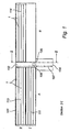
- FIG. 1 and 2 An establishment for growing plants is shown in Figs 1 and 2 .
- the establishment consists of a greenhouse 101 with two departments A and B with an intermediate work passage 102 and elongate cultivation tables 1, which in their longitudinal direction are movable between the two departments A and B.
- the elongate cultivation tables are preferably 50 m long, but can be made in different lengths in the range 10-100 m.
- Fig. 2 shows a transporting and working zone 103, doors 104, 105 and a work platform 106 which is vertically adjustable to allow working at cultivation tables arranged at different levels.
- a conveyor belt 107 is used to transport plants to and from the cultivation tables.
- the cultivation tables 1 are supported by rolls 13 according to Fig. 4 which are arranged on a stand 108 and can thus easily be moved between the departments A and B in the greenhouse.
- the rolls 13 are preferably arranged in the stand 108 at a distance of 5 m from each other.
- the cultivation tables in each department A and B are arranged in two planes, so that they can be moved between the departments A and B, for instance in such a manner that all cultivation tables are positioned in one department.
- the greenhouse establishment according to Fig. 1 also comprises two cultivation lines I and II which each consist of two cultivation rooms 111 and 112 as well as 113 and 114. A plurality of cultivation lines can be arranged side by side.
- This type of greenhouse gives great advantages since it is possible to move the tables between the departments and adjust the irrigation, light and climate conditions in different ways in the different departments.
- the type of greenhouse makes the tables easily accessible from the passage and offers effective utilisation of energy as well as cultivation area.
- the cultivation area can be made large since the cultivation tables can be arranged so closely as to entirely cover the surface in each cultivation room.
- One cultivation room 112, department B, in the cultivation line I can, for instance, be completely emptied of tables as shown in Fig. 1 .
- this room need not be heated during the time when the plants are not to be exposed to light.
- the invention is not limited to this type of greenhouse, it has been found particularly advantageous in combination therewith.
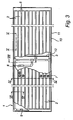
- An irrigation system as shown in Figs 3 and 4 comprises cultivation tables 1 which consist of a number of plant troughs 2 with openings 22 in the bottom of the plant troughs 2.
- the plant troughs are elongate and a succession of pot plants 7 can be grown therein.
- a main pipe 3 extends in a loop round the table 1 under the plant troughs and is, by a plurality of branch pipes 4, connected to the openings 22.
- the irrigation system is based on the principle of ebb and flow irrigation, in which a water level in the bottom of one or more plant troughs is raised, the level is maintained for a certain time and then the plant troughs are drained, i.e. completely emptied of water. The time during which the plants are exposed to water affects the growth and quality of the plants.
- the water level in the plant trough 2 is regulated by supplying or discharging water to and from the main pipe 3 that has a greater cross-sectional area.
- the supply is performed by a supply means 5 and the discharge is performed by a discharge means 6.
- the branch pipes 4, which have a smaller cross-sectional area, convey the water through the openings 22 to or from the plant trough 2.
- the frame 10 of the cultivation table is assembled of longitudinal girders 11 and transverse girders 12. Shorter reinforcement girders 15 are also arranged at certain points in the longitudinal direction of the cultivation table, which are subjected to greater loads.
- the cultivation table can be moved in the longitudinal direction for rational handling on rolls 13 arranged for the purpose, on which the table abuts on a plane contact surface of the frame 10.
- a driving device 14 is arranged for moving the table in the longitudinal direction.
- the driving device comprises an electric motor, which drives two rubber wheels which in turn engage a central rail 17 on the table 1. Pot plants 7 are grown on the cultivation table 1, of which only a few are shown.
- Means for supplying water in the form of two filling pipes 5 are connected to the main pipe 3, one at each end of the table 1.
- the filling pipes 5 are arranged in such a manner that easy filling is performed without a stationary mechanical connection simply by water being filled from above into the pipes, for instance by the table for filling being placed with a filling pipe under a water tap or the like. After irrigation has been terminated, the cultivation table can be moved to the desired position. A water column and, thus, a hydrostatic pressure form when supplying or filling water into the filling pipe as the water level 51 is being raised. Atmospheric pressure prevails at the open surface of the filling pipe.
- the main pipe is made of plastic with a main diameter of 63 mm. This diameter may be varied according to application and may conveniently be in the range 40 mm to 100 mm.
- the branch pipes are advantageously made of non-rigid plastic with a preferred inner diameter of 8 mm, but variations between 4 and 20 mm may occur in different applications.
- the plant troughs 2 are formed with a slope, i.e. a slope to each opening 22 arranged in the plant trough 2, to ensure that the plant trough 2 is completely emptied of water after irrigation.
- the measures of altitude in Fig. 5 are exaggerated to illustrate the slope in the longitudinal direction.
- Spacer elements 21 are arranged on the transverse girders 12 of the frame with a suitable distance between the spacer elements in the longitudinal direction of the plant trough.
- the spacer elements can be arranged on transverse girders, for instance, by hook means.
- the spacer elements are of two types which have different heights 21 a and 21 b, which ensure a slope to the openings 22.
- the plant trough will be slightly sloping to the openings, which allows complete emptying but still ensures uniform irrigation of all plants in the plant trough.
- the spacer elements are wedge-shaped transversely to the longitudinal direction of the plant trough, as shown in Fig. 6 , while at the same time the openings 22 are arranged along one lower long side of the plant trough 2. By a longitudinal and transverse slope, it is guaranteed that the openings are always located at the lowest point.
- a tubular means 23, which facilitates mounting of the branch pipes 4 is arranged adjacent to the plant trough in a depression formed at the opening 22.
- Fig. 7 shows schematically the path of the water down to the openings.
- the distance between the openings in the plant trough is 2.5 m, which results in highly effective drainage and emptying while at the same time this distance does not lead to the amount of water which is obtained by each plant, varying along the plant trough.
- the distance can be made shorter or longer according to application and other growing conditions, but in this application it is convenient also from the viewpoint of manufacture. A range between 1 m and 5 m gives a satisfactory result.
- the slope in the longitudinal direction of the plant trough is 8 mm for each 1.25 m of the length of the plant trough, which gives a slope of 0.64%.
- the slope is 3 mm transversely to the width of the plant trough, which is about 130 mm, which gives a slope of 2.3%.
- the distance 1.25 m is determined by the length between two openings, that is to say 2.5 m.
- the distance in the vertical direction can be between 0 and 15 mm due to surrounding factors. A slope in the range 0.2% to 2% gives good results.
- the plant trough 2 is locked to the frame by means of a locking element 24.
- the locking element also locks the neighbouring plant trough, which means that each locking element 24 locks two plant troughs.
- the locking element 24 is arranged with hook means (not shown) which engage corresponding hook means (not shown) of two neighbouring spacer elements 21.
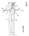
- a discharge means in the form of a drain valve is shown in Fig. 8 .
- the drain valve is a flexible tubular means 6 with a vertically adjustable outlet 64 and here comprises in particular a turnable flexible hose 61, an outlet tube 62 turnable about the axis of rotation 65 and a bent tube means 63 arranged between the hose 61 and the outlet tube 62.
- the outlet tube 62 has essentially the same cross-sectional area as the main pipe 3 in emptying.
- the outlet 64 of the outlet tube 62 is placed high up in filling, and in emptying the outlet 64 is placed at a point which is lower than the main pipe 3.
- the height between the outlet 64 and the main pipe 3 affects the discharge speed; the greater the difference in height the higher the discharge speed.
- the outlet tube 62 is made of a flexible material which can easily be changed in shape so as to be inserted between two plant troughs 2, in the closed position C, in the form of a flattened, collapsed tube.
- the outlet tube 62 is further arranged with a spring means (not shown) to provide flattening in the closed position.
- the flexible outlet tube 62 expands to achieve the maximum cross-sectional area for a high water flow through the outlet tube 62.
- the fact that the outlet tube 62 can be inserted between two plant troughs 2 guarantees that the pressure is maintained in the system since the water level 51 in the outlet tube is the same as the water level 51 in the filling pipe 5 according to Fig. 4 .
- a further advantage is that the flexible hose 61 does not require much space between two plant troughs 2, i.e. it will be accommodated without further measures being taken.
- the flexible hose 61 gives an extremely simple and reliable construction. There is a very small risk that the flexible hose 61 is clogged in operation since its inner surfaces have no edges and other elements preventing the flow of water.
- the drain valve has an extremely simple and reliable design without any risk of clogging.
- the construction also minimises the risk of water leaks with the ensuing development of algae and mould.
- the components used in the drain valve are also of such a type that they are available as standard elements.
- the discharge means 6 shown in Fig. 4 is opened by a small movement of the cultivation table 1 being made, i.e. a displacement in the longitudinal direction of the table 1, which by cooperating actuating means (not shown) between the stand and the cultivation table 1 actuates the discharge means 6 to be opened to the emptying position.
- the point of time when the discharge means 6 is to be opened is determined by the amount of water the plants should take up, which is dependent on the irrigation time.
- This solution is particularly advantageous since the driving device for moving the table 14 can be used.
- control positions (not shown) are arranged to give a signal to the control system.
- the water level 25 in the plant trough 2 is used to affect the opening of the discharge means 6.
- An overflow tube 26 is arranged in the middle of a plant trough 2. As the water level 25 reaches the overflow tube 26, a container 66 is filled with water, the weight of which increases, and when the weight is sufficient, the discharge means 6 is affected by the weight of the container.
- An advantage of the irrigation system is that the cultivation tables are movable and arranged for supply of water independently of any stationary mechanical connection. This allows easy and free movement of the cultivation tables. Since no mechanical connection is required, the filling procedure will be simple, without necessitating the connection of hoses and the like.
- a force sensor 16 which is shown in Fig. 4 , can be arranged adjacent to at least one roll 13, which force sensor 16 can thus indicate when irrigation is due. By continuous weighing of the table, irrigation can be made at the correct point of time with the correct amount of water according to the circumstances prevailing on the occasion of irrigation.
- a computer-based control system makes it possible to use data from the force sensor 16 for effective cultivation of plants.
- a force sensor (not shown) can be arranged adjacent to one or more plant troughs 2 for indicating the demand for irrigation.
- control systems can be used to maintain the conditions that are correct for the purpose.
- control systems are preferably computer-based, and by interconnecting the irrigation system and other systems of cultivation, a total control of the cultivation is obtained, with all parameters optimised.
- a flow chart according to Fig. 10 shows an example of how the method of irrigating can be performed according to the invention.
- the demand for irrigation can be determined according to step 91 by means of parameters, such as the time passed from the previous irrigation, or a signal from a force sensor 13 adjacent to the cultivation tables according to Fig. 4 .
- water is supplied according to step 92 to the filling tubes 5 according to Fig. 3 . If the time for supplying water is correct in step 93, the supply of water is stopped according to step 94.
- the drain valve 6 according to Fig. 3 is opened in step 96. A certain amount of time is to pass according to step 97 before closing the drain valve.
- step 98 the drain valve 6 according to Fig. 3 is closed.
- a control signal from the cultivation table can be used to acknowledge that drainage has been performed; if this is not the case, an alarm can be sounded.
- the process according to the flow chart in Fig. 10 is repeated during cultivation.
- the main pipe is preferably filled with water also after irrigation has been terminated, so that it will not be necessary to fill up the main pipe before the next irrigation. This means that the drainage is interrupted precisely when the plant troughs have been emptied so that there will still be water in the main pipe.
- Extruded aluminium sections 11, 12, 15 are used when manufacturing the frame 10. These are designed in order to optimise strength and allow as simple mounting as possible of the irrigation system. By using aluminium sections, the risk of damage due to corrosion is reduced. The length of these sections is adjusted to facilitate manufacture and transport.
- the transverse girders 12 are formed with holes for fitting longitudinal girders to transverse girders by means of screws (not shown).
- a reinforcing girder 15 is mounted in order to additionally optimise the use of material. For rational mounting, holes are punched in the longitudinal girder for fitting of a transverse girder by means of screws.
- the plant troughs are roll-formed from prepainted strips of steel at the mounting site. In this manner, elongate plant troughs without joints are obtained, which ensures a small risk of corrosion. Roll-forming of plant troughs can be performed in situ with equipment that can be provided by the supplier of the irrigation system. It is a comparatively quick and easy method.
- the wedge-shaped spacer elements 21 can preferably be made of plastic and allow quick and simple mounting on the transverse elements. Recesses are formed in the spacer elements for arranging a locking element 24, which hooks into corresponding hooks on the spacer element. The locking element locks two juxtaposed plant troughs 2 for optimal use of the locking element 24. An appropriate number of locking elements are arranged along the length of the plant troughs 2 to lock the plant troughs 2 to the cultivation table 1.
Landscapes
- Life Sciences & Earth Sciences (AREA)
- Environmental Sciences (AREA)
- Cultivation Receptacles Or Flower-Pots, Or Pots For Seedlings (AREA)
- Catching Or Destruction (AREA)
- Hydroponics (AREA)
- Fluid-Driven Valves (AREA)
- Manufacturing Of Electric Cables (AREA)
Claims (13)
- Bewässerungssystem für Pflanzen, umfassend wenigstens einen lang gestreckten Pflanzenkübel (2), eine Hauptleitung (3) mit einem ersten größeren Querschnittsbereich, eine Vielzahl von Öffnungen (22),
gekennzeichnet durch
eine Vielzahl von Abzweigleitungen (4), jede mit einem zweiten kleineren Querschnittsbereich, wodurch die Hauptleitung (3) mit den Öffnungen (22) verbunden ist, In Längsrichtung verteilt und im Bodenbereich des Pflanzenkübels (2) angebracht, wobei die Hauptleitung (3) weiter mit Wasserversorgungsvorrichtungen (5) und Wasseraustrittsvorrichtungen (6) verbunden ist, und wobei ein Flüssigkeitsstand im Pflanzenkübel durch Regulierung des Wasserdrucks der Hauptleitung regulierbar ist. - Bewässerungssystem nach Anspruch 1, wobei die Abzweigleitungen (4) im Wesentlichen die gleiche Länge haben.
- Bewässerungssystem nach Anspruch 1 oder 2, wobei die Versorgungsvorrichtung (5) eine aufwärts führende Leitung umfasst, die bis zu einem Stand oberhalb des Pflanzenkübelbodens reicht.
- Bewässerungssystem nach einem der vorhergehenden Ansprüche, wobei eine bewegbar angebrachte Austrittsleitung (62), die vorzugsweise den gleichen Querschnittsbereich hat wie die Hauptleitung (3), zwischen einer geschlossenen Position (C) und einer Austrittsposition (D) beweglich ist, in welcher Austrittsposition (D) der Auslass der Austrittsleitung (62) auf einem Stand unterhalb des Pflanzenkübelbodens (2) angebracht ist, vorzugsweise unterhalb der umgebenden Hauptleitung (3).
- Bewässerungssystem nach einem der vorhergehenden Ansprüche, wobei der Boden des Pflanzenkübels (2) mit einem Gefälle zu den Öffnungen (22) angeordnet ist.
- Bewässerungssystem nach einem der vorhergehenden Ansprüche, wobei das System in Verbindung mit einem bewegbaren Kultivierungstisch (1) angeordnet ist, umfassend wenigstens einen Pflanzenkübel (2), und der Kultivierungstisch (1) zur Wasserversorgung unabhängig von jeder stationären mechanischen Verbindung angeordnet ist.
- Bewässerungssystem nach einem der vorhergehenden Ansprüche, wobei ein Drucksensor (16) angrenzend an wenigstens einen Pflanzenkübel (2) angebracht ist, und dieser Drucksensor (16) so angeordnet ist, dass er die Fälligkeit der Bewässerung anzeigt.
- Verfahren zur Bewässerung von Pflanzen in einem Pflanzenkübel (2), umfassend die Schritte
der Bereitstellung der Wasserversorgung für den Pflanzenkübel (2) mittels einer Vielzahl von Öffnungen (22) im Boden desselben, durch Zufuhr von Wasser zu einer Hauptleitung (3), die mit den Öffnungen (22) durch Abzweigleitungen verbunden ist, gekennzeichnet durch
die Bereitstellung von Wasseraustritt aus dem Pflanzenkübel (2) durch Ableiten des Wassers von der Hauptleitung (3). - Verfahren zur Bewässerung von Pflanzen nach Anspruch 8, umfassend den Schritt
der Wasserversorgung in einer aufwärts führenden Leitung (5), die an die Hauptleitung (3) angeschlossen ist, um eine Wassersäule zu bilden, - Verfahren zur Bewässerung von Pflanzen nach Anspruch 8 oder 9, umfassend den Schritt des Wasseraustritts aus dem Pflanzenkübel (2) mittels Aktivierung einer Austrittsvorrichtung (6) der Hauptleitung (3).
- Verfahren zur Herstellung eines Bewässerungssystems, umfassend die Schritte
des Zusammenbaus längs und quer verlaufender Trägerelemente (11, 12) zur Bildung eines Rahmens (10),
der Anordnung der Hauptleitung (3) in dem Rahmen (10),
der Anordnung wenigstens eines lang gestreckten Pflanzenkübels (2) auf dem Rahmen (10), dadurch gekennzeichnet, dass die Öffnungen (22) im Boden des Pflanzkübels (2) mit der Hauptleitung (3) mittels Abzweigleitungen (4) verbunden sind. - Verfahren zur Herstellung eines Bewässerungssystems nach Anspruch 11, umfassend den Schritt
der Anordnung von Abstandselementen (21) auf den Querträgerelementen (12), um ein Gefälle des Pflanzenkübels (2) in Längsrichtung zu bewirken, wobei diese Abstandselemente (21) vorzugsweise keilförmig sein sollten, um gleichzeitig ein Gefälle quer zu der Längsrichtung des Pflanzenkübels (2) zu bewirken. - Verfahren zur Herstellung eines Bewässerungssystems nach Anspruch 11 oder 12, umfassend die Schritte
des Anpassens eines Metallstreifens an wenigstens einem lang gestreckten Pflanzenkübel (2),
des Stanzens von Öffnungen darin und
der Verbindung der Abzweigleitungen (4) mit den Öffnungen (22).
Applications Claiming Priority (3)
| Application Number | Priority Date | Filing Date | Title |
|---|---|---|---|
| SE0300426 | 2003-02-14 | ||
| SE0300426A SE524786C2 (sv) | 2003-02-14 | 2003-02-14 | Bevattningssystem |
| PCT/SE2004/000183 WO2004071173A1 (en) | 2003-02-14 | 2004-02-13 | The present invention relates to an irrigation system, method of irrigating and method of manufacturing an irrigation system |
Publications (2)
| Publication Number | Publication Date |
|---|---|
| EP1599087A1 EP1599087A1 (de) | 2005-11-30 |
| EP1599087B1 true EP1599087B1 (de) | 2008-07-23 |
Family
ID=20290428
Family Applications (1)
| Application Number | Title | Priority Date | Filing Date |
|---|---|---|---|
| EP04711082A Expired - Lifetime EP1599087B1 (de) | 2003-02-14 | 2004-02-13 | Bewässern und verfahren zur herstellung eines bewässerungssystems |
Country Status (8)
| Country | Link |
|---|---|
| US (1) | US20060162253A1 (de) |
| EP (1) | EP1599087B1 (de) |
| AT (1) | ATE401781T1 (de) |
| DE (1) | DE602004015255D1 (de) |
| DK (1) | DK1599087T3 (de) |
| ES (1) | ES2310283T3 (de) |
| SE (1) | SE524786C2 (de) |
| WO (1) | WO2004071173A1 (de) |
Families Citing this family (6)
| Publication number | Priority date | Publication date | Assignee | Title |
|---|---|---|---|---|
| US20070029401A1 (en) * | 2005-07-22 | 2007-02-08 | Hooshang Kaen | LAN-based sprinkler system |
| TW201100003A (en) * | 2009-06-18 | 2011-01-01 | Univ Nat Pingtung Sci & Tech | Active type water-supplying device used for plant pots |
| KR101429350B1 (ko) * | 2012-09-21 | 2014-08-13 | 경상북도(농업기술원) | 다단재배상을 이용한 유기농 인삼 연속재배시스템 |
| JP6216270B2 (ja) * | 2014-03-12 | 2017-10-18 | ヤンマー株式会社 | 移動栽培装置 |
| JP6871656B1 (ja) * | 2020-07-27 | 2021-05-12 | 藤澤建機株式会社 | 栽培設備 |
| CN114451194B (zh) * | 2022-03-21 | 2023-07-07 | 台州市羽佳温室大棚有限公司 | 一种大棚灌溉装置 |
Family Cites Families (18)
| Publication number | Priority date | Publication date | Assignee | Title |
|---|---|---|---|---|
| DE525351C (de) * | 1931-05-22 | Wilhelm Kilb | Bewaesserungs-, Beheizungs- und Belueftungsanlagen von Fruehbeeten und Gewaechshaeusern | |
| US3053011A (en) * | 1960-03-01 | 1962-09-11 | Benjamin B Silverman | System and apparatus for hydroponic growing |
| US3293799A (en) * | 1964-02-04 | 1966-12-27 | Exxon Research Engineering Co | Automatic irrigation of pot cultures in plant growth rooms and greenhouses |
| US3807088A (en) * | 1971-03-29 | 1974-04-30 | Hydroculture | Controlled environment hydroponic system |
| US4028847A (en) * | 1976-02-19 | 1977-06-14 | General Mills, Inc. | Apparatus for producing plants |
| US4183176A (en) * | 1977-04-11 | 1980-01-15 | Barfield William G | System for supplying liquids to potted plants |
| US4185414A (en) * | 1977-11-07 | 1980-01-29 | General Electric Company | Feed regulator for nutrient film agriculture system |
| US4334386A (en) * | 1980-06-16 | 1982-06-15 | Douglas Arthur Burcombe | Soiless gardening system |
| AU537171B2 (en) * | 1981-06-01 | 1984-06-14 | Matsushita Electric Industrial Co., Ltd. | Hydroponic system |
| US4584791A (en) * | 1984-08-29 | 1986-04-29 | Brandon Woods Associates | Soiless agricultural system and components therefore |
| US5020261A (en) * | 1988-01-14 | 1991-06-04 | Lishman Fred W | Moisture sensitive self-watering planter |
| DK163790C (da) * | 1989-01-10 | 1992-08-31 | Gunnar Rosenlund | Ventilsystem til planteborde |
| US5067275A (en) * | 1990-02-22 | 1991-11-26 | Constance Gerald D | Hydroponic garden |
| US5252108A (en) * | 1990-05-10 | 1993-10-12 | Banks Colin M | Hydroponic farming method and apparatus |
| DK167947B2 (da) * | 1991-09-09 | 1999-11-08 | Leif Liebmann Pedersen | Vandingsventil til dyrkningsbord samt vandingsanleag hermed |
| DE9216544U1 (de) * | 1992-11-14 | 1993-02-11 | Qtray Ltd., Gibraltar | Mobiltisch für Pflanzenzuchtbetriebe |
| NZ509411A (en) * | 1999-04-21 | 2003-08-29 | James Quinton Cameron Dick | Apparatus or installation and method for hydroponic cultivation of plants |
| AUPR303801A0 (en) * | 2001-02-09 | 2001-03-08 | A & B Hydroponics International Pty Ltd | A hydroponic apparatus |
-
2003
- 2003-02-14 SE SE0300426A patent/SE524786C2/sv not_active IP Right Cessation
-
2004
- 2004-02-13 DK DK04711082T patent/DK1599087T3/da active
- 2004-02-13 DE DE602004015255T patent/DE602004015255D1/de not_active Expired - Lifetime
- 2004-02-13 ES ES04711082T patent/ES2310283T3/es not_active Expired - Lifetime
- 2004-02-13 AT AT04711082T patent/ATE401781T1/de not_active IP Right Cessation
- 2004-02-13 EP EP04711082A patent/EP1599087B1/de not_active Expired - Lifetime
- 2004-02-13 US US10/544,930 patent/US20060162253A1/en not_active Abandoned
- 2004-02-13 WO PCT/SE2004/000183 patent/WO2004071173A1/en not_active Ceased
Also Published As
| Publication number | Publication date |
|---|---|
| DE602004015255D1 (de) | 2008-09-04 |
| US20060162253A1 (en) | 2006-07-27 |
| ES2310283T3 (es) | 2009-01-01 |
| DK1599087T3 (da) | 2008-11-17 |
| EP1599087A1 (de) | 2005-11-30 |
| SE0300426L (sv) | 2004-08-15 |
| SE524786C2 (sv) | 2004-10-05 |
| SE0300426D0 (sv) | 2003-02-14 |
| ATE401781T1 (de) | 2008-08-15 |
| WO2004071173A1 (en) | 2004-08-26 |
Similar Documents
| Publication | Publication Date | Title |
|---|---|---|
| EP3155892B1 (de) | Modularer behälter und modulares bewässerungssystem | |
| JP3787628B2 (ja) | 間欠式自動潅水装置 | |
| EP3119184B1 (de) | Vertikales gewächssystem mit etagen | |
| US3365840A (en) | Crop growing device | |
| US20060162252A1 (en) | Hydroponic device and hydroponic pot thereof | |
| KR100893651B1 (ko) | 초목용의 식재장치와 식재구조 | |
| CN100389645C (zh) | 营养液栽培装置 | |
| US20190230878A1 (en) | Tray System for Use in Hydroponic Growing | |
| US20190297803A1 (en) | Hydroponics system | |
| CN102630524A (zh) | 一种育苗温室 | |
| EP1599087B1 (de) | Bewässern und verfahren zur herstellung eines bewässerungssystems | |
| CN114615879A (zh) | 自动化生长系统 | |
| EP0169687A1 (de) | Kulturbett | |
| DE10214760B4 (de) | Gewächshaussystem | |
| JP3257629B2 (ja) | 水耕栽培施設のムービングベンチシステム | |
| GB2303286A (en) | Hydroponic equipment | |
| US20070289213A1 (en) | Irrigation systems | |
| KR20230167642A (ko) | 수경재배장치 | |
| WO2007012313A1 (de) | Anlage zum anbau von pflanzen | |
| JPH0423927A (ja) | 水耕栽培用ベッド | |
| US20230413748A1 (en) | Siphon pipe, container unit for hydroponics, and container assembly for hydroponics | |
| NL2014312B1 (en) | Method for irrigation. | |
| RU213023U1 (ru) | Установка гидропонная карусельного типа | |
| RU32969U1 (ru) | Гидропонная установка | |
| JP2007151451A (ja) | 間断式給水栽培装置 |
Legal Events
| Date | Code | Title | Description |
|---|---|---|---|
| PUAI | Public reference made under article 153(3) epc to a published international application that has entered the european phase |
Free format text: ORIGINAL CODE: 0009012 |
|
| 17P | Request for examination filed |
Effective date: 20050909 |
|
| AK | Designated contracting states |
Kind code of ref document: A1 Designated state(s): AT BE BG CH CY CZ DE DK EE ES FI FR GB GR HU IE IT LI LU MC NL PT RO SE SI SK TR |
|
| AX | Request for extension of the european patent |
Extension state: AL LT LV MK |
|
| DAX | Request for extension of the european patent (deleted) | ||
| 17Q | First examination report despatched |
Effective date: 20061206 |
|
| GRAP | Despatch of communication of intention to grant a patent |
Free format text: ORIGINAL CODE: EPIDOSNIGR1 |
|
| GRAS | Grant fee paid |
Free format text: ORIGINAL CODE: EPIDOSNIGR3 |
|
| GRAA | (expected) grant |
Free format text: ORIGINAL CODE: 0009210 |
|
| AK | Designated contracting states |
Kind code of ref document: B1 Designated state(s): AT BE BG CH CY CZ DE DK EE ES FI FR GB GR HU IE IT LI LU MC NL PT RO SE SI SK TR |
|
| REG | Reference to a national code |
Ref country code: GB Ref legal event code: FG4D |
|
| REG | Reference to a national code |
Ref country code: CH Ref legal event code: EP |
|
| REG | Reference to a national code |
Ref country code: IE Ref legal event code: FG4D |
|
| REF | Corresponds to: |
Ref document number: 602004015255 Country of ref document: DE Date of ref document: 20080904 Kind code of ref document: P |
|
| REG | Reference to a national code |
Ref country code: DK Ref legal event code: T3 |
|
| REG | Reference to a national code |
Ref country code: ES Ref legal event code: FG2A Ref document number: 2310283 Country of ref document: ES Kind code of ref document: T3 |
|
| PG25 | Lapsed in a contracting state [announced via postgrant information from national office to epo] |
Ref country code: PT Free format text: LAPSE BECAUSE OF FAILURE TO SUBMIT A TRANSLATION OF THE DESCRIPTION OR TO PAY THE FEE WITHIN THE PRESCRIBED TIME-LIMIT Effective date: 20081223 |
|
| PG25 | Lapsed in a contracting state [announced via postgrant information from national office to epo] |
Ref country code: FI Free format text: LAPSE BECAUSE OF FAILURE TO SUBMIT A TRANSLATION OF THE DESCRIPTION OR TO PAY THE FEE WITHIN THE PRESCRIBED TIME-LIMIT Effective date: 20080723 Ref country code: SI Free format text: LAPSE BECAUSE OF FAILURE TO SUBMIT A TRANSLATION OF THE DESCRIPTION OR TO PAY THE FEE WITHIN THE PRESCRIBED TIME-LIMIT Effective date: 20080723 Ref country code: AT Free format text: LAPSE BECAUSE OF FAILURE TO SUBMIT A TRANSLATION OF THE DESCRIPTION OR TO PAY THE FEE WITHIN THE PRESCRIBED TIME-LIMIT Effective date: 20080723 Ref country code: BG Free format text: LAPSE BECAUSE OF FAILURE TO SUBMIT A TRANSLATION OF THE DESCRIPTION OR TO PAY THE FEE WITHIN THE PRESCRIBED TIME-LIMIT Effective date: 20081023 |
|
| PG25 | Lapsed in a contracting state [announced via postgrant information from national office to epo] |
Ref country code: BE Free format text: LAPSE BECAUSE OF FAILURE TO SUBMIT A TRANSLATION OF THE DESCRIPTION OR TO PAY THE FEE WITHIN THE PRESCRIBED TIME-LIMIT Effective date: 20080723 |
|
| PG25 | Lapsed in a contracting state [announced via postgrant information from national office to epo] |
Ref country code: EE Free format text: LAPSE BECAUSE OF FAILURE TO SUBMIT A TRANSLATION OF THE DESCRIPTION OR TO PAY THE FEE WITHIN THE PRESCRIBED TIME-LIMIT Effective date: 20080723 |
|
| PG25 | Lapsed in a contracting state [announced via postgrant information from national office to epo] |
Ref country code: CZ Free format text: LAPSE BECAUSE OF FAILURE TO SUBMIT A TRANSLATION OF THE DESCRIPTION OR TO PAY THE FEE WITHIN THE PRESCRIBED TIME-LIMIT Effective date: 20080723 Ref country code: SK Free format text: LAPSE BECAUSE OF FAILURE TO SUBMIT A TRANSLATION OF THE DESCRIPTION OR TO PAY THE FEE WITHIN THE PRESCRIBED TIME-LIMIT Effective date: 20080723 Ref country code: RO Free format text: LAPSE BECAUSE OF FAILURE TO SUBMIT A TRANSLATION OF THE DESCRIPTION OR TO PAY THE FEE WITHIN THE PRESCRIBED TIME-LIMIT Effective date: 20080723 |
|
| PLBE | No opposition filed within time limit |
Free format text: ORIGINAL CODE: 0009261 |
|
| STAA | Information on the status of an ep patent application or granted ep patent |
Free format text: STATUS: NO OPPOSITION FILED WITHIN TIME LIMIT |
|
| 26N | No opposition filed |
Effective date: 20090424 |
|
| PG25 | Lapsed in a contracting state [announced via postgrant information from national office to epo] |
Ref country code: IT Free format text: LAPSE BECAUSE OF FAILURE TO SUBMIT A TRANSLATION OF THE DESCRIPTION OR TO PAY THE FEE WITHIN THE PRESCRIBED TIME-LIMIT Effective date: 20080723 |
|
| PG25 | Lapsed in a contracting state [announced via postgrant information from national office to epo] |
Ref country code: MC Free format text: LAPSE BECAUSE OF NON-PAYMENT OF DUE FEES Effective date: 20090228 |
|
| REG | Reference to a national code |
Ref country code: CH Ref legal event code: PL |
|
| PG25 | Lapsed in a contracting state [announced via postgrant information from national office to epo] |
Ref country code: LI Free format text: LAPSE BECAUSE OF NON-PAYMENT OF DUE FEES Effective date: 20090228 Ref country code: CH Free format text: LAPSE BECAUSE OF NON-PAYMENT OF DUE FEES Effective date: 20090228 |
|
| PG25 | Lapsed in a contracting state [announced via postgrant information from national office to epo] |
Ref country code: SE Free format text: LAPSE BECAUSE OF FAILURE TO SUBMIT A TRANSLATION OF THE DESCRIPTION OR TO PAY THE FEE WITHIN THE PRESCRIBED TIME-LIMIT Effective date: 20081023 Ref country code: IE Free format text: LAPSE BECAUSE OF NON-PAYMENT OF DUE FEES Effective date: 20090213 |
|
| PG25 | Lapsed in a contracting state [announced via postgrant information from national office to epo] |
Ref country code: GR Free format text: LAPSE BECAUSE OF FAILURE TO SUBMIT A TRANSLATION OF THE DESCRIPTION OR TO PAY THE FEE WITHIN THE PRESCRIBED TIME-LIMIT Effective date: 20081024 |
|
| PG25 | Lapsed in a contracting state [announced via postgrant information from national office to epo] |
Ref country code: LU Free format text: LAPSE BECAUSE OF NON-PAYMENT OF DUE FEES Effective date: 20090213 |
|
| PGFP | Annual fee paid to national office [announced via postgrant information from national office to epo] |
Ref country code: DK Payment date: 20110127 Year of fee payment: 8 |
|
| PGFP | Annual fee paid to national office [announced via postgrant information from national office to epo] |
Ref country code: DE Payment date: 20110203 Year of fee payment: 8 Ref country code: NL Payment date: 20110214 Year of fee payment: 8 Ref country code: FR Payment date: 20110216 Year of fee payment: 8 |
|
| PG25 | Lapsed in a contracting state [announced via postgrant information from national office to epo] |
Ref country code: HU Free format text: LAPSE BECAUSE OF FAILURE TO SUBMIT A TRANSLATION OF THE DESCRIPTION OR TO PAY THE FEE WITHIN THE PRESCRIBED TIME-LIMIT Effective date: 20090124 |
|
| PGFP | Annual fee paid to national office [announced via postgrant information from national office to epo] |
Ref country code: ES Payment date: 20110217 Year of fee payment: 8 Ref country code: GB Payment date: 20110204 Year of fee payment: 8 |
|
| PG25 | Lapsed in a contracting state [announced via postgrant information from national office to epo] |
Ref country code: TR Free format text: LAPSE BECAUSE OF FAILURE TO SUBMIT A TRANSLATION OF THE DESCRIPTION OR TO PAY THE FEE WITHIN THE PRESCRIBED TIME-LIMIT Effective date: 20080723 |
|
| PG25 | Lapsed in a contracting state [announced via postgrant information from national office to epo] |
Ref country code: CY Free format text: LAPSE BECAUSE OF FAILURE TO SUBMIT A TRANSLATION OF THE DESCRIPTION OR TO PAY THE FEE WITHIN THE PRESCRIBED TIME-LIMIT Effective date: 20080723 |
|
| REG | Reference to a national code |
Ref country code: NL Ref legal event code: V1 Effective date: 20120901 |
|
| GBPC | Gb: european patent ceased through non-payment of renewal fee |
Effective date: 20120213 |
|
| REG | Reference to a national code |
Ref country code: DK Ref legal event code: EBP |
|
| REG | Reference to a national code |
Ref country code: FR Ref legal event code: ST Effective date: 20121031 |
|
| REG | Reference to a national code |
Ref country code: DE Ref legal event code: R119 Ref document number: 602004015255 Country of ref document: DE Effective date: 20120901 |
|
| PG25 | Lapsed in a contracting state [announced via postgrant information from national office to epo] |
Ref country code: NL Free format text: LAPSE BECAUSE OF NON-PAYMENT OF DUE FEES Effective date: 20120901 Ref country code: FR Free format text: LAPSE BECAUSE OF NON-PAYMENT OF DUE FEES Effective date: 20120229 Ref country code: GB Free format text: LAPSE BECAUSE OF NON-PAYMENT OF DUE FEES Effective date: 20120213 |
|
| PG25 | Lapsed in a contracting state [announced via postgrant information from national office to epo] |
Ref country code: DE Free format text: LAPSE BECAUSE OF NON-PAYMENT OF DUE FEES Effective date: 20120901 |
|
| REG | Reference to a national code |
Ref country code: ES Ref legal event code: FD2A Effective date: 20130708 |
|
| PG25 | Lapsed in a contracting state [announced via postgrant information from national office to epo] |
Ref country code: ES Free format text: LAPSE BECAUSE OF NON-PAYMENT OF DUE FEES Effective date: 20120214 |
|
| PG25 | Lapsed in a contracting state [announced via postgrant information from national office to epo] |
Ref country code: DK Free format text: LAPSE BECAUSE OF NON-PAYMENT OF DUE FEES Effective date: 20120229 |