EP1599279B1 - Reacteur à agitateur segmente et procédé - Google Patents
Reacteur à agitateur segmente et procédé Download PDFInfo
- Publication number
- EP1599279B1 EP1599279B1 EP04701302A EP04701302A EP1599279B1 EP 1599279 B1 EP1599279 B1 EP 1599279B1 EP 04701302 A EP04701302 A EP 04701302A EP 04701302 A EP04701302 A EP 04701302A EP 1599279 B1 EP1599279 B1 EP 1599279B1
- Authority
- EP
- European Patent Office
- Prior art keywords
- reactor
- blades
- agitator
- curved
- process according
- Prior art date
- Legal status (The legal status is an assumption and is not a legal conclusion. Google has not performed a legal analysis and makes no representation as to the accuracy of the status listed.)
- Expired - Lifetime
Links
- 238000000034 method Methods 0.000 title claims abstract description 23
- 230000008569 process Effects 0.000 claims abstract description 19
- 239000000126 substance Substances 0.000 claims abstract description 16
- 230000009969 flowable effect Effects 0.000 claims abstract description 4
- 230000002093 peripheral effect Effects 0.000 claims abstract 2
- 229920000642 polymer Polymers 0.000 claims description 22
- 238000006243 chemical reaction Methods 0.000 claims description 20
- 239000003054 catalyst Substances 0.000 claims description 13
- 239000007789 gas Substances 0.000 claims description 12
- 238000002156 mixing Methods 0.000 claims description 11
- 239000000178 monomer Substances 0.000 claims description 10
- 239000007788 liquid Substances 0.000 claims description 7
- 229920000098 polyolefin Polymers 0.000 claims description 7
- 239000002826 coolant Substances 0.000 claims description 6
- 239000011261 inert gas Substances 0.000 claims description 5
- 230000004888 barrier function Effects 0.000 claims description 3
- 238000004519 manufacturing process Methods 0.000 claims description 3
- IJGRMHOSHXDMSA-UHFFFAOYSA-N Atomic nitrogen Chemical compound N#N IJGRMHOSHXDMSA-UHFFFAOYSA-N 0.000 claims 2
- 238000001704 evaporation Methods 0.000 claims 1
- 229910052757 nitrogen Inorganic materials 0.000 claims 1
- 238000005201 scrubbing Methods 0.000 claims 1
- 239000002245 particle Substances 0.000 description 23
- 238000003756 stirring Methods 0.000 description 12
- QQONPFPTGQHPMA-UHFFFAOYSA-N Propene Chemical compound CC=C QQONPFPTGQHPMA-UHFFFAOYSA-N 0.000 description 9
- 125000004805 propylene group Chemical group [H]C([H])([H])C([H])([*:1])C([H])([H])[*:2] 0.000 description 8
- 125000000217 alkyl group Chemical group 0.000 description 6
- -1 polypropylene Polymers 0.000 description 6
- 239000007787 solid Substances 0.000 description 5
- 230000008901 benefit Effects 0.000 description 4
- 238000001816 cooling Methods 0.000 description 4
- 239000000203 mixture Substances 0.000 description 4
- 229920001155 polypropylene Polymers 0.000 description 4
- 239000004743 Polypropylene Substances 0.000 description 3
- SJJCABYOVIHNPZ-UHFFFAOYSA-N cyclohexyl-dimethoxy-methylsilane Chemical compound CO[Si](C)(OC)C1CCCCC1 SJJCABYOVIHNPZ-UHFFFAOYSA-N 0.000 description 3
- 238000013461 design Methods 0.000 description 3
- 238000009826 distribution Methods 0.000 description 3
- 230000000694 effects Effects 0.000 description 3
- 239000000463 material Substances 0.000 description 3
- 230000007704 transition Effects 0.000 description 3
- VOITXYVAKOUIBA-UHFFFAOYSA-N triethylaluminium Chemical compound CC[Al](CC)CC VOITXYVAKOUIBA-UHFFFAOYSA-N 0.000 description 3
- UFHFLCQGNIYNRP-UHFFFAOYSA-N Hydrogen Chemical compound [H][H] UFHFLCQGNIYNRP-UHFFFAOYSA-N 0.000 description 2
- CTQNGGLPUBDAKN-UHFFFAOYSA-N O-Xylene Chemical compound CC1=CC=CC=C1C CTQNGGLPUBDAKN-UHFFFAOYSA-N 0.000 description 2
- BLRPTPMANUNPDV-UHFFFAOYSA-N Silane Chemical compound [SiH4] BLRPTPMANUNPDV-UHFFFAOYSA-N 0.000 description 2
- 125000003118 aryl group Chemical group 0.000 description 2
- 239000003795 chemical substances by application Substances 0.000 description 2
- 238000000576 coating method Methods 0.000 description 2
- 125000000753 cycloalkyl group Chemical group 0.000 description 2
- 238000005516 engineering process Methods 0.000 description 2
- 239000012530 fluid Substances 0.000 description 2
- 238000005243 fluidization Methods 0.000 description 2
- 239000001257 hydrogen Substances 0.000 description 2
- 229910052739 hydrogen Inorganic materials 0.000 description 2
- 238000006116 polymerization reaction Methods 0.000 description 2
- 238000002360 preparation method Methods 0.000 description 2
- 238000012546 transfer Methods 0.000 description 2
- 230000009471 action Effects 0.000 description 1
- 239000012190 activator Substances 0.000 description 1
- 239000000654 additive Substances 0.000 description 1
- 239000012159 carrier gas Substances 0.000 description 1
- 238000006555 catalytic reaction Methods 0.000 description 1
- 238000001311 chemical methods and process Methods 0.000 description 1
- 238000004140 cleaning Methods 0.000 description 1
- 239000011248 coating agent Substances 0.000 description 1
- 238000010276 construction Methods 0.000 description 1
- 238000007796 conventional method Methods 0.000 description 1
- 239000000112 cooling gas Substances 0.000 description 1
- 230000007423 decrease Effects 0.000 description 1
- 238000007872 degassing Methods 0.000 description 1
- 239000000975 dye Substances 0.000 description 1
- 238000011049 filling Methods 0.000 description 1
- 238000011010 flushing procedure Methods 0.000 description 1
- 239000011521 glass Substances 0.000 description 1
- 230000005484 gravity Effects 0.000 description 1
- 238000010438 heat treatment Methods 0.000 description 1
- 239000008240 homogeneous mixture Substances 0.000 description 1
- 150000002431 hydrogen Chemical class 0.000 description 1
- 230000006872 improvement Effects 0.000 description 1
- 239000003112 inhibitor Substances 0.000 description 1
- 238000003541 multi-stage reaction Methods 0.000 description 1
- 210000000056 organ Anatomy 0.000 description 1
- 239000000843 powder Substances 0.000 description 1
- 238000004886 process control Methods 0.000 description 1
- 238000012545 processing Methods 0.000 description 1
- 238000005086 pumping Methods 0.000 description 1
- 239000002994 raw material Substances 0.000 description 1
- 239000012495 reaction gas Substances 0.000 description 1
- 239000002683 reaction inhibitor Substances 0.000 description 1
- 238000009991 scouring Methods 0.000 description 1
- 238000000926 separation method Methods 0.000 description 1
- 238000007493 shaping process Methods 0.000 description 1
- 229910000077 silane Inorganic materials 0.000 description 1
- 239000002904 solvent Substances 0.000 description 1
- 239000000725 suspension Substances 0.000 description 1
- 238000009827 uniform distribution Methods 0.000 description 1
- XLYOFNOQVPJJNP-UHFFFAOYSA-N water Substances O XLYOFNOQVPJJNP-UHFFFAOYSA-N 0.000 description 1
- 239000008096 xylene Substances 0.000 description 1
Images




Classifications
-
- B—PERFORMING OPERATIONS; TRANSPORTING
- B01—PHYSICAL OR CHEMICAL PROCESSES OR APPARATUS IN GENERAL
- B01F—MIXING, e.g. DISSOLVING, EMULSIFYING OR DISPERSING
- B01F27/00—Mixers with rotary stirring devices in fixed receptacles; Kneaders
- B01F27/05—Stirrers
- B01F27/11—Stirrers characterised by the configuration of the stirrers
- B01F27/112—Stirrers characterised by the configuration of the stirrers with arms, paddles, vanes or blades
- B01F27/1123—Stirrers characterised by the configuration of the stirrers with arms, paddles, vanes or blades sickle-shaped, i.e. curved in at least one direction
-
- B—PERFORMING OPERATIONS; TRANSPORTING
- B01—PHYSICAL OR CHEMICAL PROCESSES OR APPARATUS IN GENERAL
- B01F—MIXING, e.g. DISSOLVING, EMULSIFYING OR DISPERSING
- B01F27/00—Mixers with rotary stirring devices in fixed receptacles; Kneaders
- B01F27/50—Pipe mixers, i.e. mixers wherein the materials to be mixed flow continuously through pipes, e.g. column mixers
-
- B—PERFORMING OPERATIONS; TRANSPORTING
- B01—PHYSICAL OR CHEMICAL PROCESSES OR APPARATUS IN GENERAL
- B01F—MIXING, e.g. DISSOLVING, EMULSIFYING OR DISPERSING
- B01F27/00—Mixers with rotary stirring devices in fixed receptacles; Kneaders
- B01F27/80—Mixers with rotary stirring devices in fixed receptacles; Kneaders with stirrers rotating about a substantially vertical axis
- B01F27/90—Mixers with rotary stirring devices in fixed receptacles; Kneaders with stirrers rotating about a substantially vertical axis with paddles or arms
-
- B—PERFORMING OPERATIONS; TRANSPORTING
- B01—PHYSICAL OR CHEMICAL PROCESSES OR APPARATUS IN GENERAL
- B01F—MIXING, e.g. DISSOLVING, EMULSIFYING OR DISPERSING
- B01F35/00—Accessories for mixers; Auxiliary operations or auxiliary devices; Parts or details of general application
- B01F35/90—Heating or cooling systems
- B01F35/91—Heating or cooling systems using gas or liquid injected into the material, e.g. using liquefied carbon dioxide or steam
-
- B—PERFORMING OPERATIONS; TRANSPORTING
- B01—PHYSICAL OR CHEMICAL PROCESSES OR APPARATUS IN GENERAL
- B01J—CHEMICAL OR PHYSICAL PROCESSES, e.g. CATALYSIS OR COLLOID CHEMISTRY; THEIR RELEVANT APPARATUS
- B01J19/00—Chemical, physical or physico-chemical processes in general; Their relevant apparatus
- B01J19/0053—Details of the reactor
- B01J19/0066—Stirrers
-
- B—PERFORMING OPERATIONS; TRANSPORTING
- B01—PHYSICAL OR CHEMICAL PROCESSES OR APPARATUS IN GENERAL
- B01J—CHEMICAL OR PHYSICAL PROCESSES, e.g. CATALYSIS OR COLLOID CHEMISTRY; THEIR RELEVANT APPARATUS
- B01J19/00—Chemical, physical or physico-chemical processes in general; Their relevant apparatus
- B01J19/18—Stationary reactors having moving elements inside
- B01J19/1806—Stationary reactors having moving elements inside resulting in a turbulent flow of the reactants, such as in centrifugal-type reactors, or having a high Reynolds-number
-
- B—PERFORMING OPERATIONS; TRANSPORTING
- B01—PHYSICAL OR CHEMICAL PROCESSES OR APPARATUS IN GENERAL
- B01F—MIXING, e.g. DISSOLVING, EMULSIFYING OR DISPERSING
- B01F27/00—Mixers with rotary stirring devices in fixed receptacles; Kneaders
- B01F27/05—Stirrers
- B01F27/07—Stirrers characterised by their mounting on the shaft
- B01F27/072—Stirrers characterised by their mounting on the shaft characterised by the disposition of the stirrers with respect to the rotating axis
- B01F27/0724—Stirrers characterised by their mounting on the shaft characterised by the disposition of the stirrers with respect to the rotating axis directly mounted on the rotating axis
-
- B—PERFORMING OPERATIONS; TRANSPORTING
- B01—PHYSICAL OR CHEMICAL PROCESSES OR APPARATUS IN GENERAL
- B01F—MIXING, e.g. DISSOLVING, EMULSIFYING OR DISPERSING
- B01F27/00—Mixers with rotary stirring devices in fixed receptacles; Kneaders
- B01F27/05—Stirrers
- B01F27/11—Stirrers characterised by the configuration of the stirrers
- B01F27/19—Stirrers with two or more mixing elements mounted in sequence on the same axis
- B01F27/192—Stirrers with two or more mixing elements mounted in sequence on the same axis with dissimilar elements
-
- B—PERFORMING OPERATIONS; TRANSPORTING
- B01—PHYSICAL OR CHEMICAL PROCESSES OR APPARATUS IN GENERAL
- B01F—MIXING, e.g. DISSOLVING, EMULSIFYING OR DISPERSING
- B01F27/00—Mixers with rotary stirring devices in fixed receptacles; Kneaders
- B01F27/21—Mixers with rotary stirring devices in fixed receptacles; Kneaders characterised by their rotating shafts
- B01F27/2122—Hollow shafts
-
- B—PERFORMING OPERATIONS; TRANSPORTING
- B01—PHYSICAL OR CHEMICAL PROCESSES OR APPARATUS IN GENERAL
- B01J—CHEMICAL OR PHYSICAL PROCESSES, e.g. CATALYSIS OR COLLOID CHEMISTRY; THEIR RELEVANT APPARATUS
- B01J2219/00—Chemical, physical or physico-chemical processes in general; Their relevant apparatus
- B01J2219/00049—Controlling or regulating processes
- B01J2219/00051—Controlling the temperature
- B01J2219/00121—Controlling the temperature by direct heating or cooling
- B01J2219/00123—Controlling the temperature by direct heating or cooling adding a temperature modifying medium to the reactants
-
- B—PERFORMING OPERATIONS; TRANSPORTING
- B01—PHYSICAL OR CHEMICAL PROCESSES OR APPARATUS IN GENERAL
- B01J—CHEMICAL OR PHYSICAL PROCESSES, e.g. CATALYSIS OR COLLOID CHEMISTRY; THEIR RELEVANT APPARATUS
- B01J2219/00—Chemical, physical or physico-chemical processes in general; Their relevant apparatus
- B01J2219/00049—Controlling or regulating processes
- B01J2219/00164—Controlling or regulating processes controlling the flow
- B01J2219/00166—Controlling or regulating processes controlling the flow controlling the residence time inside the reactor vessel
-
- B—PERFORMING OPERATIONS; TRANSPORTING
- B01—PHYSICAL OR CHEMICAL PROCESSES OR APPARATUS IN GENERAL
- B01J—CHEMICAL OR PHYSICAL PROCESSES, e.g. CATALYSIS OR COLLOID CHEMISTRY; THEIR RELEVANT APPARATUS
- B01J2219/00—Chemical, physical or physico-chemical processes in general; Their relevant apparatus
- B01J2219/00761—Details of the reactor
- B01J2219/00763—Baffles
- B01J2219/00779—Baffles attached to the stirring means
-
- B—PERFORMING OPERATIONS; TRANSPORTING
- B01—PHYSICAL OR CHEMICAL PROCESSES OR APPARATUS IN GENERAL
- B01J—CHEMICAL OR PHYSICAL PROCESSES, e.g. CATALYSIS OR COLLOID CHEMISTRY; THEIR RELEVANT APPARATUS
- B01J2219/00—Chemical, physical or physico-chemical processes in general; Their relevant apparatus
- B01J2219/18—Details relating to the spatial orientation of the reactor
- B01J2219/185—Details relating to the spatial orientation of the reactor vertical
-
- B—PERFORMING OPERATIONS; TRANSPORTING
- B01—PHYSICAL OR CHEMICAL PROCESSES OR APPARATUS IN GENERAL
- B01J—CHEMICAL OR PHYSICAL PROCESSES, e.g. CATALYSIS OR COLLOID CHEMISTRY; THEIR RELEVANT APPARATUS
- B01J2219/00—Chemical, physical or physico-chemical processes in general; Their relevant apparatus
- B01J2219/19—Details relating to the geometry of the reactor
- B01J2219/194—Details relating to the geometry of the reactor round
- B01J2219/1941—Details relating to the geometry of the reactor round circular or disk-shaped
- B01J2219/1946—Details relating to the geometry of the reactor round circular or disk-shaped conical
-
- C—CHEMISTRY; METALLURGY
- C08—ORGANIC MACROMOLECULAR COMPOUNDS; THEIR PREPARATION OR CHEMICAL WORKING-UP; COMPOSITIONS BASED THEREON
- C08F—MACROMOLECULAR COMPOUNDS OBTAINED BY REACTIONS ONLY INVOLVING CARBON-TO-CARBON UNSATURATED BONDS
- C08F110/00—Homopolymers of unsaturated aliphatic hydrocarbons having only one carbon-to-carbon double bond
- C08F110/04—Monomers containing three or four carbon atoms
- C08F110/06—Propene
-
- Y—GENERAL TAGGING OF NEW TECHNOLOGICAL DEVELOPMENTS; GENERAL TAGGING OF CROSS-SECTIONAL TECHNOLOGIES SPANNING OVER SEVERAL SECTIONS OF THE IPC; TECHNICAL SUBJECTS COVERED BY FORMER USPC CROSS-REFERENCE ART COLLECTIONS [XRACs] AND DIGESTS
- Y10—TECHNICAL SUBJECTS COVERED BY FORMER USPC
- Y10S—TECHNICAL SUBJECTS COVERED BY FORMER USPC CROSS-REFERENCE ART COLLECTIONS [XRACs] AND DIGESTS
- Y10S526/00—Synthetic resins or natural rubbers -- part of the class 520 series
- Y10S526/918—Polymerization reactors for addition polymer preparation
Definitions
- the present invention relates to a device for carrying out chemical and / or physical processes, and to a process for producing polyolefins.
- Known reactors for the present purposes are basically flow tubes or stirred tanks.
- a device for homogenizing glass is known. This consists of a vertical tube with internally arranged on a shaft agitator blades. The wings are curved in opposite directions and have a constant from the shaft to the inner edge of the tube sheet width.
- US Pat. No. 4,460,278 discloses a tube reactor for the purpose of polymerization reactions, which has a plurality of upwardly and downwardly bent pairs of impeller blades with intervening disks. The purpose of this device is to create a circular flow around the ends of blade pairs.
- the present invention therefore has the object to provide a reactor for physical and / or chemical processes, which combines the advantageous characteristics of flow tube and stirred tank.
- a device for carrying out chemical and physical processes consisting of a preferably (vertical) cylindrical container with inlets and outlets, and a central shaft and arranged at this, up Radial impellers extending close to the wall.
- the stirring blades are curved in the circumferential direction. formed and combined as stirrers in pairs (one above the other) into groups, wherein the wings of the one organ of the group are radially concave and the wings of the adjacent member are radially convexly curved.
- Such a reactor according to the invention can be used in particular for producing homogeneous mixtures, for carrying out reactions between solid and / or liquid and / or gaseous substances, for heating or cooling, for coating particles and the like.
- its simple construction also allows processes under high pressure or high temperature.
- the residence time of the particles is very homogeneous when passing through the tubular reactor, also on the height of different measures, such as. B. partially cooling, addition or discharge of Substances take place, for example, can be carried out with gases, a transverse scouring when solid particles are treated in the reactor, or it can be carried out several reaction steps with different reaction components.
- Another improvement i. in particular faster mixing and narrower residence time distribution can, with a taper of the wings towards their free ends, z. B. be achieved by a trapezoidal shape of the wings, which takes into account the increase in circumferential speed in the radial direction.
- the transverse promotion can be improved by a spiral curvature of the wings, preferably in the form of a logarithmic or Archimedean spiral.
- the wings may also be employed at an angle to the longitudinal axis of the supporting shaft, in order to achieve a vertical promotion.
- the blades of the stirring element can be turned in opposite directions in such a way that they move towards one another in their area of action in order to intensify mixing.
- Solution processes have the disadvantage that the solvent used must be removed from the polymer and recovered.
- the polymer is significantly backmixed so that they can be described by a continuously operated stirred tank.
- Such backmixed processes allow only limited control of the polymer composition over the residence time of a polymer particle in the reaction zone.
- a not inconsiderable portion of the polymer particles are already removed from the reactor at an early point in the reaction, which leads to a lower catalyst utilization.
- Another important aspect is the amount of transitional material that is produced in a reactor when changing from a product A to B. This is essentially determined by the residence time behavior of the reactor system.
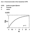
- Fig. 5 shows the residence time behavior of a classical CSTR.
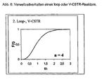
- Fig. 6 shows the residence time behavior of a loop or V-CSTR reactor.
- a system has the following features: It is a vertical, stirred reactor that is divided into segments (groups). For the reaction, it is initially irrelevant whether the main product flow is up or down.
- the reactor consists of at least 2, preferably 4, more preferably more than 12 theoretical segments, whereby the following consideration applies to the individual segment (see Fig. 7).
- the design of the segment is mainly based on the gas velocities.
- the operating point of the reactor is in the range between the gas velocity 0 and the fluidization limit preferably in the range of 0.5 to 0.8 times the gas velocity at the fluidization point.
- the residence time behavior of such a reactor system can be described by the graph (see Fig. 8) with respect to a product property F.
- Such a reactor system allows product transitions in less than a residence time.
- Each segment is equipped with a stirrer, which allows efficient horizontal mixing and thus a uniform distribution of cooling medium over the entire reaction chamber and a high relative speed ensures the particles to each other.
- Rhackorgane which can allow such a mixing behavior as stated above z. B. have the shape of a logarithmic spiral wherein the cross-sectional profile and design of the area at the Rrockerspitzen and the stirrer axis are such that the mass flow is largely ensured even in the edge zones, ie in the outermost and innermost workspace of the stirrer.
- a particular advantage is that stirrers with Archimedean or logarithmic spiral shape are self-cleaning.
- the height and diameter of the segments can be adapted to the particular kinetics of the catalyst system by selecting the reactor geometry and the arrangement and shaping of the stirring elements.
- a back-mixed zone can be provided for better mixing of the catalyst and for more effective heat removal.
- the stirrer is modified accordingly. Suitable for this purpose, for example, baffles or other internals that force mixing in the direction of the stirrer axis.
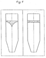
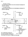
- Figure 1 shows, on the left, the flow characteristics of a fluid medium passing through a vertical cylindrical container (1) with conventional centers, vertical stirrers, mounted on a driven coaxial shaft.
- the flow rate decreases mainly due to the edge friction from the inside to the outside, so that the central particles leave the reactor much earlier than those located in the edge region, ie the residence time is very unequal.
- the right figure illustrates the effect of the procedure according to the invention.
- the flow rate of all particles is the same, they pass the reactor in a closed front as a piston flow, but with permanent mixing transverse to the reactor axis.
- the reaction rate, the heat transfer and the like it is therefore possible to define zones to which further reaction components or else reaction inhibitors can be added from the outside or via a hollow shaft.
- multistage reactions in a single reactor housing or different reaction parameters such as temperature, concentration can be carried out vary in a reactor housing.
- the conditions apply both to the preferred standing, as well as a horizontal or inclined arrangement of the reactor.
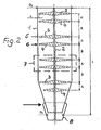
- Figure 2 illustrates the basic structure of the reactor according to the invention. It consists of a particular standing cylindrical container 1 with a central shaft 2, which may also be hollow.
- the shaft 2 carries as stirrers 5, 6, stirring blades 3, 4, which are each combined to form superimposed and interacting groups 7, wherein the wings 3, 4, are spirally curved in opposite directions, so that a stirrer 5 is a substantially radially outward directed promotion and the other 6 such causes inward.
- the distances A between the stirring elements 5, 6, are less than the distances B of the groups 7 from each other.
- the clearance A between the impellers 3, 4 and the wall of the container is matched to the particle sizes passing through the reactor, ie it can increase in the flow direction as the particle sizes increase.
- this may be conical near the bottom 8.
- a hollow shaft and corresponding outlet openings (not shown) or hollow impeller formed substances can be introduced into the process or withdrawn from this.
- FIG. 3 shows a further application of the reactor according to the invention.
- the polyolefin particles obtained by the catalytic reaction in Figure 3 and grown with the catalyst contain unreacted gaseous monomer components.
- the product is transferred (continuously) to a second reactor designed with similar impeller groups and purged with inert gas at a slight overpressure or atmospheric pressure with intensive stirring, again with the flow tube corresponding residence time ensures an absolutely uniform degassing.
- the inert gas (N 2 ) can be introduced countercurrently, for example via the bottom, or, as indicated herein, via a hollow shaft and the stirring vanes.
- additives e.g. Add dyes, which in turn are very homogeneously mixed with the polymer.
- FIG. 4 shows a top view of various embodiments of the stirring elements, wherein the wings 3, which are curved in the same direction, lie in a different plane than the oppositely curved ones 4.
- impeller pairs are used, which can also be arranged crosswise.
- the curvatures of the wings can be made stronger or weaker, and an offset arrangement of the wings within a group in the adjacent planes is also possible.
Landscapes
- Chemical & Material Sciences (AREA)
- Chemical Kinetics & Catalysis (AREA)
- Organic Chemistry (AREA)
- Polymerisation Methods In General (AREA)
- Physical Or Chemical Processes And Apparatus (AREA)
- Mixers Of The Rotary Stirring Type (AREA)
- Accessories For Mixers (AREA)
- Processing Of Solid Wastes (AREA)
- Devices And Processes Conducted In The Presence Of Fluids And Solid Particles (AREA)
- Crushing And Grinding (AREA)
Claims (13)
- Dispositif pour mettre en oeuvre des processus chimiques et physiques, dans lequel on mélange entre elles des substances fluides, et constitué d'un récipient cylindrique (1) avec admission et évacuation, ainsi que d'un arbre central (2) qui y est fixé, des ailettes d'agitation radiales (3 ; 4) s'étendant jusqu'à la paroi avec les caractéristiques suivantes :a) les ailettes d'agitation (3 ; 4) sont formées de façon courbée dans la direction de la périphérie etb) sont réunies par paires les unes au-dessus des autres en organes d'agitation (5 ; 6), formant des groupes (7), oùc) les ailettes (3) d'un organe (5) du groupe (7) sont recourbées radialement de façon concave et les ailettes (4) de l'autre organe (6) sont recourbées radialement de façon convexe,
caractérisé en ce qued) les ailettes (3 ; 4) s'amincissent vers leurs extrémités libres. - Dispositif selon la revendication 1 ou 2, caractérisé en ce que la courbure des ailettes (3 ; 4) présente la forme d'une spirale.
- Dispositif selon la revendication 1 ou 2, caractérisé en ce que la courbure est de forme logarithmique ou en vis d'Archimède.
- Dispositif selon l'une des revendications 1 à 3, caractérisé en ce que les ailettes (3 ; 4) sont disposées dans le sens axial en vue du transport vertical des substances dans le sens axial.
- Dispositif selon la revendication 4, caractérisé en ce que les ailettes (3 ; 4) des organes d'agitation présentent des angles de marche en sens contraire.
- Dispositif selon l'une des revendications 1 à 5, caractérisé en ce que des éléments de barrage sont disposés entre les groupes d'organes d'agitation (5 ; 6).
- Dispositif selon l'une des revendications 1 à 6, caractérisé en ce que des admissions et évacuations sont disposées selon un certain intervalle dans la paroi du récipient en vue de l'apport de composants de la réaction et/ou de réfrigérants dans les substances fluides.
- Dispositif de production de polymères dans un réacteur tubulaire, dans lequel on déplace les composants de la réaction en direction axiale à travers le réacteur, et on les y fait se déplacer au moyen d'ailettes d'agitation recourbées en sens contraire et assemblées par paires les unes au-dessus des autres pour constituer des groupes, ce déplacement s'effectuant de manière essentiellement perpendiculaire à l'axe du réacteur, une fois dans sa direction et une fois en direction opposée, et l'on mélange les composants de la réaction de façon intensive, caractérisé en ce que les ailettes s'amincissent en direction de leur extrémité.
- Procédé selon la revendication 8, caractérisé en ce qu'on dispose dans le réacteur un polymère d'oléfine et en ce qu'on y ajoute un monomère et un système catalyseur.
- Procédé selon la revendication 9, caractérisé en ce qu'on refroidit le contenu du réacteur en ajoutant un monomère liquide, en ce que dans l'opération on fait évaporer le monomère et en ce qu'on retire celui-ci sous forme gazeuse.
- Procédé selon l'une des revendications 8 à 1 0, caractérisé en ce qu'on introduit le monomère liquide en plusieurs endroits successivement dans le réacteur dans la direction de déplacement du polymère.
- Procédé selon l'une des revendications 9 à 1 1, caractérisé en ce qu'on introduit un gaz barrière par sections dans le réacteur depuis l'extérieur ou depuis un arbre creux portant les ailettes d'agitation ou par les ailettes, et en ce qu'on retire ce gaz de façon radiale.
- Procédé selon l'une des revendications 9 à 12, caractérisé en ce qu'on transfère le produit qui quitte le réacteur dans un second réacteur muni de paires d'ailettes d'agitation analogues, et en ce qu'on débarrasse ce second réacteur des résidus de monomère en balayant avec un gaz inerte, de préférence l'azote.
Applications Claiming Priority (3)
| Application Number | Priority Date | Filing Date | Title |
|---|---|---|---|
| DE10310091A DE10310091A1 (de) | 2003-03-06 | 2003-03-06 | Segmentierter Rührreaktor |
| DE10310091 | 2003-03-06 | ||
| PCT/EP2004/000116 WO2004078329A1 (fr) | 2003-03-06 | 2004-01-10 | Reacteur a agitateur segmente |
Publications (2)
| Publication Number | Publication Date |
|---|---|
| EP1599279A1 EP1599279A1 (fr) | 2005-11-30 |
| EP1599279B1 true EP1599279B1 (fr) | 2006-09-13 |
Family
ID=32864261
Family Applications (1)
| Application Number | Title | Priority Date | Filing Date |
|---|---|---|---|
| EP04701302A Expired - Lifetime EP1599279B1 (fr) | 2003-03-06 | 2004-01-10 | Reacteur à agitateur segmente et procédé |
Country Status (11)
| Country | Link |
|---|---|
| US (1) | US7459506B2 (fr) |
| EP (1) | EP1599279B1 (fr) |
| JP (1) | JP4669470B2 (fr) |
| CN (1) | CN100400147C (fr) |
| AT (1) | ATE339244T1 (fr) |
| BR (1) | BRPI0408130A (fr) |
| DE (2) | DE10310091A1 (fr) |
| EA (1) | EA007436B1 (fr) |
| ES (1) | ES2273203T3 (fr) |
| WO (1) | WO2004078329A1 (fr) |
| ZA (1) | ZA200506453B (fr) |
Families Citing this family (20)
| Publication number | Priority date | Publication date | Assignee | Title |
|---|---|---|---|---|
| DE102010023793A1 (de) * | 2010-06-15 | 2011-12-15 | J. F. Knauer Industrie-Elektronik Gmbh | Vorrichtung und Verfahren zum Einmischen von Konditioniermittel, insbesondere Flockmittel, in Schlämme |
| EP2598538B1 (fr) * | 2010-07-30 | 2016-10-26 | Total Research & Technology Feluy | Utilisation d'un système de préparation de suspension de catalyseur |
| KR101040927B1 (ko) | 2011-03-30 | 2011-06-16 | (주)플록마스터 | 슬러지 파쇄용 믹스장치 |
| US10647790B2 (en) | 2011-06-30 | 2020-05-12 | W. R. Grace & Co.-Conn. | Process for gas-phase polymerization having high bed bulk density |
| RU2505349C1 (ru) * | 2012-07-25 | 2014-01-27 | Василий Агафонович Лотов | Центробежный смеситель |
| CN103734895A (zh) * | 2013-12-13 | 2014-04-23 | 云南中烟昆船瑞升科技有限公司 | 多功能连续浸提固液分离组合机 |
| CN104056588B (zh) * | 2014-06-19 | 2015-12-09 | 奉化拓升商贸有限公司 | 一种制备三氟甲基苯胺的反应釜 |
| DE102015106512A1 (de) | 2015-04-28 | 2016-11-03 | EKATO Rühr- und Mischtechnik GmbH | Rührorganvorrichtung |
| CN108472618B (zh) | 2016-01-29 | 2020-04-28 | 埃克森美孚化学专利公司 | 用于生产官能化烯烃基聚合物的系统和方法 |
| JP6169772B1 (ja) | 2016-12-07 | 2017-07-26 | マイクロ波化学株式会社 | 撹拌翼、および処理装置 |
| CN107812485B (zh) * | 2017-11-13 | 2024-05-03 | 江西怡杉环保股份有限公司 | 搅拌装置 |
| CN109019990B (zh) * | 2018-09-21 | 2021-07-20 | 深圳市齐欣实业有限公司 | 一种储油罐底油污泥净化回收处理工艺装置 |
| CN110563870B (zh) * | 2019-09-18 | 2022-04-01 | 青岛科技大学 | 一种合成橡胶工业化生产方法及实施该方法的工业装置 |
| CN110787748B (zh) * | 2019-11-04 | 2022-02-15 | 江阴市澄阳新技术有限公司 | 搅拌轴及具有其的反应釜 |
| CN110975703A (zh) * | 2019-11-30 | 2020-04-10 | 徐州海天石化有限公司 | 一种润滑油搅拌装置 |
| CN111117675B (zh) * | 2020-01-07 | 2021-03-19 | 山东理工大学 | 一种分段螺旋搅拌式生物质热解液化系统 |
| CN114459868B (zh) * | 2022-01-20 | 2024-02-02 | 爱博能(广州)科学技术有限公司 | 用于粉状固体混合物样品的隔板取样式初步分离装置 |
| CN114772697B (zh) * | 2022-06-16 | 2022-09-02 | 深圳市至臻生物科技有限公司 | 一种可吸氢的高浓度富氢水制备装置 |
| CN115652732B (zh) * | 2022-12-28 | 2023-03-17 | 喜跃发国际环保新材料股份有限公司 | 一种改性沥青的加工工艺及加工系统 |
| CN119955041A (zh) * | 2025-04-09 | 2025-05-09 | 山东友泉新材料有限公司 | 一种酚醛树脂的生产方法及生产装置 |
Family Cites Families (16)
| Publication number | Priority date | Publication date | Assignee | Title |
|---|---|---|---|---|
| DE281168C (fr) * | ||||
| US2569459A (en) * | 1945-08-09 | 1951-10-02 | Corning Glass Works | Method and apparatus for stirring glass |
| DE1218265B (de) | 1962-08-01 | 1966-06-02 | Basf Ag | Wendelruehrer |
| DE1720292B2 (de) * | 1967-08-10 | 1975-05-22 | Basf Ag, 6700 Ludwigshafen | Verfahren zur Herstellung von Propylenpolymerisaten |
| US4003712A (en) * | 1970-07-29 | 1977-01-18 | Union Carbide Corporation | Fluidized bed reactor |
| JPS5230539B1 (fr) * | 1970-08-08 | 1977-08-09 | ||
| DE2705556C3 (de) * | 1977-02-10 | 1980-07-31 | Bayer Ag, 5090 Leverkusen | Polymerisationsreaktor |
| DE2803407C2 (de) * | 1978-01-26 | 1982-12-02 | Hans 4930 Detmold Kimmel | Rührwerkzeug |
| JPS57125202A (en) * | 1981-01-28 | 1982-08-04 | Mitsui Toatsu Chem Inc | Device for continuous bulk polymerization |
| US4438074A (en) * | 1981-07-21 | 1984-03-20 | Phillips Petroleum Company | Continuous polymerization reactor |
| US4921919A (en) * | 1985-12-10 | 1990-05-01 | Amoco Corporation | Method and apparatus for minimizing polymer agglomerate or lump formation in a gas-phase polypropylene polymerization reactor |
| IT1275573B (it) | 1995-07-20 | 1997-08-07 | Spherilene Spa | Processo ed apparecchiatura per la pomimerizzazione in fase gas delle alfa-olefine |
| EP0891381B2 (fr) | 1996-04-01 | 2006-05-24 | The Dow Chemical Company | Polymerisation en solution d'olefines |
| CA2201224C (fr) * | 1997-03-27 | 2004-12-07 | Annette Lynn Burke | Element double de melange par cisaillement |
| US6350054B1 (en) | 1997-12-08 | 2002-02-26 | Bp Corporation North America Inc. | Agitator for a horizontal polymerization reactor having contiguous paddle stations with paddles and sub-stations with sub-station paddles |
| SG82693A1 (en) | 1999-09-03 | 2001-08-21 | Sumitomo Chemical Co | Fluidized bed reactor for gas phase olefin polymerization, process for polymerizing olefin and process for producing olefin polymer |
-
2003
- 2003-03-06 DE DE10310091A patent/DE10310091A1/de not_active Withdrawn
-
2004
- 2004-01-10 CN CNB2004800061616A patent/CN100400147C/zh not_active Expired - Fee Related
- 2004-01-10 DE DE502004001482T patent/DE502004001482D1/de not_active Expired - Lifetime
- 2004-01-10 US US10/548,288 patent/US7459506B2/en not_active Expired - Fee Related
- 2004-01-10 EP EP04701302A patent/EP1599279B1/fr not_active Expired - Lifetime
- 2004-01-10 JP JP2006504384A patent/JP4669470B2/ja not_active Expired - Fee Related
- 2004-01-10 EA EA200501418A patent/EA007436B1/ru not_active IP Right Cessation
- 2004-01-10 ES ES04701302T patent/ES2273203T3/es not_active Expired - Lifetime
- 2004-01-10 BR BRPI0408130-7A patent/BRPI0408130A/pt not_active IP Right Cessation
- 2004-01-10 WO PCT/EP2004/000116 patent/WO2004078329A1/fr not_active Ceased
- 2004-01-10 AT AT04701302T patent/ATE339244T1/de not_active IP Right Cessation
-
2005
- 2005-08-12 ZA ZA2005/06453A patent/ZA200506453B/en unknown
Also Published As
| Publication number | Publication date |
|---|---|
| ES2273203T3 (es) | 2007-05-01 |
| DE502004001482D1 (de) | 2006-10-26 |
| JP4669470B2 (ja) | 2011-04-13 |
| EA007436B1 (ru) | 2006-10-27 |
| CN1756591A (zh) | 2006-04-05 |
| EA200501418A1 (ru) | 2006-02-24 |
| US20060104874A1 (en) | 2006-05-18 |
| ZA200506453B (en) | 2007-01-31 |
| EP1599279A1 (fr) | 2005-11-30 |
| BRPI0408130A (pt) | 2006-03-01 |
| JP2006519897A (ja) | 2006-08-31 |
| ATE339244T1 (de) | 2006-10-15 |
| WO2004078329A1 (fr) | 2004-09-16 |
| DE10310091A1 (de) | 2004-09-16 |
| US7459506B2 (en) | 2008-12-02 |
| CN100400147C (zh) | 2008-07-09 |
Similar Documents
| Publication | Publication Date | Title |
|---|---|---|
| EP1599279B1 (fr) | Reacteur à agitateur segmente et procédé | |
| DE69809468T2 (de) | Rührer für subfluidisiertes feststoffbett in quench-gekühlten dampfphasen polymerisationsreaktoren | |
| DE69413690T2 (de) | Verfahren zur olefinpolymerisation in einem fliessbettreaktor | |
| DE69531374T2 (de) | Gasphasenverteilerplatte für einen Gasphasenpolymerisationsapparat | |
| DE69706148T2 (de) | Verfahren und apparat für die polymerisation von olefinmonomeren | |
| DE69219340T2 (de) | Polymerisationsreaktor | |
| DE69601569T2 (de) | Verfahren und vorrichtung zur gasphasenpolymerisation von alpha-olefinen | |
| DE69317331T2 (de) | Verfahren und Apparat für Gasphase-Polymerisation von Olefinen | |
| DE60214038T2 (de) | Gasphasen olefin polymerisationsverfahren mit der benutzung von einem dual donor ziegler-natta katalysator | |
| DE60006676T2 (de) | Fluidisierte wirbelschichtpolymerisation | |
| DE69119121T2 (de) | Verfahren und Vorrichtung für alpha-Olefinpolymerisation in der Gasphase | |
| DE2556418A1 (de) | Vorrichtung und verfahren zur dampfphasenpolymerisation von monomeren | |
| DE69705726T2 (de) | Transport von polymerpartikeln zwischen gasphasenpolymerisations reaktoren | |
| DE19711022A1 (de) | Verwendung eines Mehrstufenrührers zur Herstellung von Polymerisaten | |
| DE1632413B2 (de) | Polymerisationsreaktor | |
| DE69825310T2 (de) | Verfahren und vorrichtung zur herstellung von polymeren | |
| DE2540918A1 (de) | Polymerisation einer verfluessigten c tief 1-8 raffineriegasmischung | |
| WO2000049055A1 (fr) | PROCEDE ET DISPOSITIF DE POLYMERISATION EN PHASE GAZEUSE D'α-OLEFINES | |
| DE2520591B2 (de) | Verfahren und Vorrichtung zur kontinuierlichen Behandlung von wäßrigen Homo- und Copolymerisatdispersionen, deren PoIymeranteil mindestens 50 Gew.-% polymerisiertes Vinylchlorid enthält, mit Inertgasen | |
| DE102004054628A1 (de) | Vorrichtung zur Gasphasenpolymerisation von Olefinen, insbesondere Ethylen | |
| DE1645631A1 (de) | Polykondensationsvorrichtung und -verfahren | |
| DE69102125T2 (de) | Gas-phase-Polymerisationsapparat und dessen Steuerungssystem. | |
| DE112013002494T5 (de) | Olefin-Polymerisator, Polyolefinherstellungssystem und Verfahren zur Herstellung von Polyolefin | |
| DE1595067B2 (de) | Verfahren zur polymerisation von vinalchlorid | |
| DE112006001239T5 (de) | Gasphasen-Wirbelschichtreaktor, Mehrgefäß-Polymerisationsreaktor und Verfahren zur Olefinpolymerherstellung |
Legal Events
| Date | Code | Title | Description |
|---|---|---|---|
| PUAI | Public reference made under article 153(3) epc to a published international application that has entered the european phase |
Free format text: ORIGINAL CODE: 0009012 |
|
| 17P | Request for examination filed |
Effective date: 20050813 |
|
| AK | Designated contracting states |
Kind code of ref document: A1 Designated state(s): AT BE BG CH CY CZ DE DK EE ES FI FR GB GR HU IE IT LI LU MC NL PT RO SE SI SK TR |
|
| AX | Request for extension of the european patent |
Extension state: AL LT LV MK |
|
| GRAP | Despatch of communication of intention to grant a patent |
Free format text: ORIGINAL CODE: EPIDOSNIGR1 |
|
| RTI1 | Title (correction) |
Free format text: SEGMENTED AGITATOR REACTOR AND METHOD |
|
| DAX | Request for extension of the european patent (deleted) | ||
| GRAS | Grant fee paid |
Free format text: ORIGINAL CODE: EPIDOSNIGR3 |
|
| GRAA | (expected) grant |
Free format text: ORIGINAL CODE: 0009210 |
|
| RAP1 | Party data changed (applicant data changed or rights of an application transferred) |
Owner name: NOVOLEN TECHNOLOGY HOLDINGS C.V. |
|
| AK | Designated contracting states |
Kind code of ref document: B1 Designated state(s): AT BE BG CH CY CZ DE DK EE ES FI FR GB GR HU IE IT LI LU MC NL PT RO SE SI SK TR |
|
| PG25 | Lapsed in a contracting state [announced via postgrant information from national office to epo] |
Ref country code: SI Free format text: LAPSE BECAUSE OF FAILURE TO SUBMIT A TRANSLATION OF THE DESCRIPTION OR TO PAY THE FEE WITHIN THE PRESCRIBED TIME-LIMIT Effective date: 20060913 Ref country code: IT Free format text: LAPSE BECAUSE OF FAILURE TO SUBMIT A TRANSLATION OF THE DESCRIPTION OR TO PAY THE FEE WITHIN THE PRESCRIBED TIME-LIMIT;WARNING: LAPSES OF ITALIAN PATENTS WITH EFFECTIVE DATE BEFORE 2007 MAY HAVE OCCURRED AT ANY TIME BEFORE 2007. THE CORRECT EFFECTIVE DATE MAY BE DIFFERENT FROM THE ONE RECORDED. Effective date: 20060913 Ref country code: SK Free format text: LAPSE BECAUSE OF FAILURE TO SUBMIT A TRANSLATION OF THE DESCRIPTION OR TO PAY THE FEE WITHIN THE PRESCRIBED TIME-LIMIT Effective date: 20060913 Ref country code: RO Free format text: LAPSE BECAUSE OF FAILURE TO SUBMIT A TRANSLATION OF THE DESCRIPTION OR TO PAY THE FEE WITHIN THE PRESCRIBED TIME-LIMIT Effective date: 20060913 Ref country code: CZ Free format text: LAPSE BECAUSE OF FAILURE TO SUBMIT A TRANSLATION OF THE DESCRIPTION OR TO PAY THE FEE WITHIN THE PRESCRIBED TIME-LIMIT Effective date: 20060913 Ref country code: GB Free format text: LAPSE BECAUSE OF FAILURE TO SUBMIT A TRANSLATION OF THE DESCRIPTION OR TO PAY THE FEE WITHIN THE PRESCRIBED TIME-LIMIT Effective date: 20060913 Ref country code: IE Free format text: LAPSE BECAUSE OF FAILURE TO SUBMIT A TRANSLATION OF THE DESCRIPTION OR TO PAY THE FEE WITHIN THE PRESCRIBED TIME-LIMIT Effective date: 20060913 |
|
| REG | Reference to a national code |
Ref country code: GB Ref legal event code: FG4D Free format text: NOT ENGLISH |
|
| REG | Reference to a national code |
Ref country code: CH Ref legal event code: EP |
|
| REG | Reference to a national code |
Ref country code: IE Ref legal event code: FG4D Free format text: LANGUAGE OF EP DOCUMENT: GERMAN |
|
| REF | Corresponds to: |
Ref document number: 502004001482 Country of ref document: DE Date of ref document: 20061026 Kind code of ref document: P |
|
| PG25 | Lapsed in a contracting state [announced via postgrant information from national office to epo] |
Ref country code: BG Free format text: LAPSE BECAUSE OF FAILURE TO SUBMIT A TRANSLATION OF THE DESCRIPTION OR TO PAY THE FEE WITHIN THE PRESCRIBED TIME-LIMIT Effective date: 20061213 Ref country code: SE Free format text: LAPSE BECAUSE OF FAILURE TO SUBMIT A TRANSLATION OF THE DESCRIPTION OR TO PAY THE FEE WITHIN THE PRESCRIBED TIME-LIMIT Effective date: 20061213 Ref country code: DK Free format text: LAPSE BECAUSE OF FAILURE TO SUBMIT A TRANSLATION OF THE DESCRIPTION OR TO PAY THE FEE WITHIN THE PRESCRIBED TIME-LIMIT Effective date: 20061213 |
|
| PG25 | Lapsed in a contracting state [announced via postgrant information from national office to epo] |
Ref country code: MC Free format text: LAPSE BECAUSE OF NON-PAYMENT OF DUE FEES Effective date: 20070131 |
|
| ET | Fr: translation filed | ||
| PG25 | Lapsed in a contracting state [announced via postgrant information from national office to epo] |
Ref country code: PT Free format text: LAPSE BECAUSE OF FAILURE TO SUBMIT A TRANSLATION OF THE DESCRIPTION OR TO PAY THE FEE WITHIN THE PRESCRIBED TIME-LIMIT Effective date: 20070226 |
|
| GBV | Gb: ep patent (uk) treated as always having been void in accordance with gb section 77(7)/1977 [no translation filed] |
Effective date: 20060913 |
|
| REG | Reference to a national code |
Ref country code: IE Ref legal event code: FD4D |
|
| REG | Reference to a national code |
Ref country code: ES Ref legal event code: FG2A Ref document number: 2273203 Country of ref document: ES Kind code of ref document: T3 |
|
| PLBE | No opposition filed within time limit |
Free format text: ORIGINAL CODE: 0009261 |
|
| STAA | Information on the status of an ep patent application or granted ep patent |
Free format text: STATUS: NO OPPOSITION FILED WITHIN TIME LIMIT |
|
| 26N | No opposition filed |
Effective date: 20070614 |
|
| PG25 | Lapsed in a contracting state [announced via postgrant information from national office to epo] |
Ref country code: GR Free format text: LAPSE BECAUSE OF FAILURE TO SUBMIT A TRANSLATION OF THE DESCRIPTION OR TO PAY THE FEE WITHIN THE PRESCRIBED TIME-LIMIT Effective date: 20061214 |
|
| PG25 | Lapsed in a contracting state [announced via postgrant information from national office to epo] |
Ref country code: AT Free format text: LAPSE BECAUSE OF NON-PAYMENT OF DUE FEES Effective date: 20070110 |
|
| PG25 | Lapsed in a contracting state [announced via postgrant information from national office to epo] |
Ref country code: EE Free format text: LAPSE BECAUSE OF FAILURE TO SUBMIT A TRANSLATION OF THE DESCRIPTION OR TO PAY THE FEE WITHIN THE PRESCRIBED TIME-LIMIT Effective date: 20060913 |
|
| REG | Reference to a national code |
Ref country code: CH Ref legal event code: PL |
|
| PG25 | Lapsed in a contracting state [announced via postgrant information from national office to epo] |
Ref country code: LI Free format text: LAPSE BECAUSE OF NON-PAYMENT OF DUE FEES Effective date: 20080131 Ref country code: CH Free format text: LAPSE BECAUSE OF NON-PAYMENT OF DUE FEES Effective date: 20080131 |
|
| PGFP | Annual fee paid to national office [announced via postgrant information from national office to epo] |
Ref country code: FI Payment date: 20090114 Year of fee payment: 6 Ref country code: NL Payment date: 20090104 Year of fee payment: 6 |
|
| PGFP | Annual fee paid to national office [announced via postgrant information from national office to epo] |
Ref country code: BE Payment date: 20090216 Year of fee payment: 6 |
|
| PG25 | Lapsed in a contracting state [announced via postgrant information from national office to epo] |
Ref country code: CY Free format text: LAPSE BECAUSE OF FAILURE TO SUBMIT A TRANSLATION OF THE DESCRIPTION OR TO PAY THE FEE WITHIN THE PRESCRIBED TIME-LIMIT Effective date: 20060913 Ref country code: LU Free format text: LAPSE BECAUSE OF NON-PAYMENT OF DUE FEES Effective date: 20070110 |
|
| PG25 | Lapsed in a contracting state [announced via postgrant information from national office to epo] |
Ref country code: HU Free format text: LAPSE BECAUSE OF FAILURE TO SUBMIT A TRANSLATION OF THE DESCRIPTION OR TO PAY THE FEE WITHIN THE PRESCRIBED TIME-LIMIT Effective date: 20070314 |
|
| PGFP | Annual fee paid to national office [announced via postgrant information from national office to epo] |
Ref country code: FR Payment date: 20090113 Year of fee payment: 6 |
|
| BERE | Be: lapsed |
Owner name: *NOVOLEN TECHNOLOGY HOLDINGS C.V. Effective date: 20100131 |
|
| REG | Reference to a national code |
Ref country code: NL Ref legal event code: V1 Effective date: 20100801 |
|
| REG | Reference to a national code |
Ref country code: FR Ref legal event code: ST Effective date: 20100930 |
|
| PG25 | Lapsed in a contracting state [announced via postgrant information from national office to epo] |
Ref country code: NL Free format text: LAPSE BECAUSE OF NON-PAYMENT OF DUE FEES Effective date: 20100801 Ref country code: FR Free format text: LAPSE BECAUSE OF NON-PAYMENT OF DUE FEES Effective date: 20100201 |
|
| PG25 | Lapsed in a contracting state [announced via postgrant information from national office to epo] |
Ref country code: FI Free format text: LAPSE BECAUSE OF NON-PAYMENT OF DUE FEES Effective date: 20100110 |
|
| PG25 | Lapsed in a contracting state [announced via postgrant information from national office to epo] |
Ref country code: BE Free format text: LAPSE BECAUSE OF NON-PAYMENT OF DUE FEES Effective date: 20100131 |
|
| PG25 | Lapsed in a contracting state [announced via postgrant information from national office to epo] |
Ref country code: TR Free format text: LAPSE BECAUSE OF NON-PAYMENT OF DUE FEES Effective date: 20110727 |
|
| PGFP | Annual fee paid to national office [announced via postgrant information from national office to epo] |
Ref country code: TR Payment date: 20081225 Year of fee payment: 6 |
|
| PGFP | Annual fee paid to national office [announced via postgrant information from national office to epo] |
Ref country code: DE Payment date: 20140129 Year of fee payment: 11 |
|
| PGFP | Annual fee paid to national office [announced via postgrant information from national office to epo] |
Ref country code: ES Payment date: 20140127 Year of fee payment: 11 |
|
| REG | Reference to a national code |
Ref country code: DE Ref legal event code: R082 Ref document number: 502004001482 Country of ref document: DE Representative=s name: PATENTANWAELTE WEICKMANN & WEICKMANN, DE Ref country code: DE Ref legal event code: R082 Ref document number: 502004001482 Country of ref document: DE Representative=s name: WEICKMANN & WEICKMANN PATENTANWAELTE - RECHTSA, DE |
|
| REG | Reference to a national code |
Ref country code: DE Ref legal event code: R119 Ref document number: 502004001482 Country of ref document: DE |
|
| PG25 | Lapsed in a contracting state [announced via postgrant information from national office to epo] |
Ref country code: DE Free format text: LAPSE BECAUSE OF NON-PAYMENT OF DUE FEES Effective date: 20150801 |
|
| REG | Reference to a national code |
Ref country code: ES Ref legal event code: FD2A Effective date: 20160829 |
|
| PG25 | Lapsed in a contracting state [announced via postgrant information from national office to epo] |
Ref country code: ES Free format text: LAPSE BECAUSE OF NON-PAYMENT OF DUE FEES Effective date: 20150111 |