EP1600052A2 - Andaineuse rotative remorquée - Google Patents
Andaineuse rotative remorquée Download PDFInfo
- Publication number
- EP1600052A2 EP1600052A2 EP05009622A EP05009622A EP1600052A2 EP 1600052 A2 EP1600052 A2 EP 1600052A2 EP 05009622 A EP05009622 A EP 05009622A EP 05009622 A EP05009622 A EP 05009622A EP 1600052 A2 EP1600052 A2 EP 1600052A2
- Authority
- EP
- European Patent Office
- Prior art keywords
- rotary
- rotary rake
- rake
- drawbar
- wheels
- Prior art date
- Legal status (The legal status is an assumption and is not a legal conclusion. Google has not performed a legal analysis and makes no representation as to the accuracy of the status listed.)
- Granted
Links
Images



Classifications
-
- A—HUMAN NECESSITIES
- A01—AGRICULTURE; FORESTRY; ANIMAL HUSBANDRY; HUNTING; TRAPPING; FISHING
- A01D—HARVESTING; MOWING
- A01D78/00—Haymakers with tines moving with respect to the machine
- A01D78/08—Haymakers with tines moving with respect to the machine with tine-carrying rotary heads or wheels
- A01D78/10—Haymakers with tines moving with respect to the machine with tine-carrying rotary heads or wheels the tines rotating about a substantially vertical axis
- A01D78/1085—Having two rows of rotors on two different horizontal lines perpendicular to the advance direction of the machine
Definitions
- the invention relates to a towed rotary windrower according to the preamble of Claim 1.
- towed rotary windrower of this type are the wheels only the second rotary rake with its chassis over the Drawbar of the second rotary rake from the transport position in at least one laterally displaced working position steerable and by means of a drawbar and on Chassis engaging adjusting detectable.
- the first rotary gyro becomes with the main drawbar substantially in the direction of the longitudinal center plane Tractor on its wheels so dragged that its tine orbit on both sides reaches out over the tractor wheel tracks.
- Running in the transport position the second rotary rake the first in the direction of the longitudinal center axis of the tractor to.
- the second rotary rake In a Butlerschwad working position, the second rotary rake is opposite the first rotary rake offset laterally on the side to which the first rotary rake the Promotes crop. In a single swath working position, however, is the second rotary rake offset laterally relative to the first rotary rake to the side of the page turned away, on which the first rotary rake promotes the crop. In this way two single swaths are laid, the z. B. as a night swath or strong Emtegutanfall for a small press forms.
- the respective transfer of the second Rotary gyroscope is by a corresponding rotation of the chassis relative to Drawbar of the second rotary rake set.
- Two individual swaths are less economical for further processing, e.g. through a baler, a shredder or the like, as a double swath or two juxtaposed or superimposed double swath. Because in both working positions the tractor with its wheels in on the Field lying crop moves, the crop can be in the soft soil if necessary which is detrimental to efficient computer work and pollution of the emmental with soil. As the drawbar with regard to a short transport length and good maneuverability only as long as necessary, forms the rear rotary rake in the single swath position a narrower single swath than the first rotary top (limited working width).
- EP 1 145 620 A EP 1 060 651 A, EP 0 845 199 A and EP 0 876 751 A.
- the invention is based on the object, a towed rotary windrower of to create the type mentioned above, with the at least at the edge of the field a more efficient Raking is possible as with the known.
- the tractor drives in sufficient Distance from the edge of the field.
- the first rotary top right to or above the Field edge conveys crop from the field edge inwards to the second rotary rake, the transferred crop with the crop picked up by him in the Vollschwad brings.
- the Vollschwad is well processed, for example by a baler.
- the efficiency of the Rachaille is also high in the field, because by means of the forced adjustment of the first rotary rake so far relative to the longitudinal central axis
- the tractor can be towed laterally offset that the tractor with a Wheel track on an already cleaned ground strip drives.
- a Vollswad formed.
- the risk of not crushing crops pushed into the ground Soiling crops with soil is thus halved. If necessary leaves
- the first rotary gyro even move so far aside that both Traktorradspuren be shaped in the clean field strip.
- other intermediate Vollschwad working positions can be adjusted by means of the forced adjustment device for Adjust the first rotary rake, so that the application width of the towed rotary rake is considerably expanded.
- the forced adjustment device for the first rotary rake is also useful if in addition to the second rotary rake still a third or even another rotary rake should be provided. in principle can, on the one hand to rake efficiently at the edge of the field, or to the pollution of the To minimize harvesting, the forced adjustment even when a towed Rotary windrower be appropriate, equipped only with a large rotary rake is.
- the rotary top prongs are controlled so that in each Working position results in an optimal image.
- the forced adjustment device also leads to the important advantage of a maximum working width in the single swath position according to the sum of the diameter of the tine circumscribing the Rotary gyroscope without the training of the drawbar of the second rotary gyro have to. Because the first rotary top can be moved so far to the side, to no Overlapping is given more.
- the single swath have the same width to each other and substantially equal degrees of filling.
- both rotary gyros are relative to the same side offset to the longitudinal center axis of the tractor so that at least one Traktorradspur in an already cleaned field strip lies.
- the second rotary top can do this expedient to be towed completely outside the two Traktorradspuren.
- the second rotary rake can, as is known, for a higher Rech alloy be designed as the first rotary rake.
- At least one hydraulic cylinder which can be controlled by the tractor as desired or automatically.
- the hydraulic cylinder is supported on an abutment of the main drawbar and steers The wheels of the first rotary rake so that this offset as desired to the side becomes.
- the support frame If the wheels are not steerable a supporting frame of the landing gear are arranged, it is expedient, the support frame to turn by means of the hydraulic cylinder. If the wheels on the support frame are arranged steerable, it may be appropriate to the wheels directly by means of Steer hydraulic cylinder accordingly.
- the wheels are not steerable on the support frame and the support frame itself unrotatable on the drawbar or on the gear housing the rotary rake is arranged, it is expedient, in the main drawbar a To provide articulated joint, in which a main drawbar end part relative to the to the tractor extending main drawbar can bend around the wheels accordingly to steer and steer.
- a shaft axis axis rotatably through the gear housing and with steering devices of the wheels to couple, wherein the hydraulic cylinder engages via a lever on the shaft and adjusts the wheel steering position, and expediently the tine control accordingly adjusted.
- the main drawbar has a main drawbar end piece which can be bent off, the Articulated between the gyro axis and the drawbar for the drawbar second rotary rake, that is, relatively close to the rotor axis.
- the Hydraulic cylinder engages a corresponding abutment of the main drawbar end part to bend this relative to the main drawbar until the desired Side offset of the first rotary rake is set.
- the chassis of the second rotary rake steerable wheels has the chassis of the second rotary rake steerable wheels, and is for Steering the wheels an automatic or optionally activated sequential control intended.
- the wheels of the landing gear of the second rotary rake can be like the Impellers of the chassis of the first rotary rake are steered.
- the sequence control serves to ensure that the second rotary rake the first rotary rake in an exact Predictable and selectable track follows, both in the transport position in straight or cornering, or in a working position with straight or Cornering. This sequential control makes it easier to turn around in sharp turns, for example, when entering the field or on the forecourt, and facilitates it also, to reverse the bends.
- the correct one is Overlap between the first and second rotary rakes finely adjustable and maintainable.
- the steering of the wheels of the second rotary rake takes place, for example. in the opposite direction to the steering direction of the tractor, that is, with the tractor turning to the right the second rotary rake is moved to the left side.
- the rotary gyros are essentially without overlap and therefore with driven maximum working width, forming equal width single swath.
- the sequence control a steering command generator having the relative kink angle of either the main drawbar to the longitudinal central axis of the tractor or in the tow point between the main drawbar and the Removing drawbar and converted into appropriate steering commands.
- the steering commander For example, may have a sensing lever on the main drawbar connected and hinged to a reference point on the tractor. alternative This feeler could also be between the drawbar and the main drawbar be provided in the area of the Werins. The latter solution is the Preference given because the connection conditions on the tractor are simplified. Furthermore, it may be appropriate to provide an actuator at the Switzerlandyak to the Adjust the bending angle between the main drawbar and the drawbar and be able to set.
- a Einzelschwad working position is advantageous in the means of the Forced adjustment of the first rotary rake and by means of its own steering device also the second rotary top with angled main drawbar and in opposite directions angled drawbar are each offset so far to the side that no Overlap more arises, but equal width with maximum possible working width Individual swaths are formed.
- a trailer shown in Fig. 1 consists of a tractor S and a towed Rotary mower K, which is shown in Fig. 1 in the transport position T and the tractor S in a transport direction DT is towed (straight ahead).
- the tractor S drives with its rear wheels 1, 2 (and the front wheels, not shown) in Traktorradspuren 3, 4.
- On a towing device 5 of the tractor S is with a towing connection 6, a main drawbar H of the rotary rake K at least laterally pivotally connected.
- the main drawbar H contains an articulated joint 7 with in approximately ground-parallel bending axis and is connected to a transmission housing 8 of a first Rotary gyro R1 connected, the tines 9 define a tine circulation path 10.
- the tines 9 are controllable with a tine control device, not shown.
- the first rotary rake R1 has its own chassis F1 with an example with the transmission housing 8 connected support frame 12, to the plurality of wheels 11 are arranged. In the embodiment shown, only two wheels 11 shown, but it could also be provided more than two wheels.
- a drawbar Z for a second rotary rake R2 to one approximately to Bottom vertical axis pivoted.
- the drawbar Z contains at least an articulated joint 7 'with approximately ground-parallel bending axis and is connected to the transmission housing 8 'of the second rotary rake R2 connected.
- the tines 9 'of the second Rotary rakes R2 define a tine circulation path 10 'whose diameter is the same or different from the diameter of the tine orbit 10 may be. Also the tines 9 'are controlled.
- the second rotary rake R2 has a support frame 12 'for ground wheels 11', which belong to the chassis F2.
- the drawbars H, Z extend approximately in extension of the longitudinal central axis of the tractor S.
- a forced adjustment device V provided with the first rotary rake R1 relative to Longitudinal axis Y of the tractor S can move to one or the other side.
- Fig. 2 shows the team in a field edge Vollschwad working position.
- the tractor S moves in a direction DR approximately parallel to a field edge FR, between the Traktorradspur 4 and the field edge FR adhered to a "safe" transverse distance X. becomes.
- the first rotary rake R1 is relative to the longitudinal center axis Y of the tractor S to Side of the field edge FR offset, such that the zinc orbit 10 to close to the one to, or over the edge of the field FR.
- the main drawbar is H pivoted counterclockwise. This laterally offset position of the first Rotary gyro R1 is adjusted by means of the forced adjustment device V thereby that the wheels 11 in the direction DR first taken to the right and then run (as shown) parallel to the field edge FR.
- the second rotary rake R2 is relative to the first rotary rake R1 to the other side offset, such that in the direction DR a certain overlap exists and picked up by the first rotary rake R1 crop to the second rotary rake R2 passed and is introduced by this in a Vollschwad VS.
- the second Rotary rake R2 is offset so far that its tine orbit 10 'a Distance of the one Traktorradspur 4 complies, and on the other Traktorradspur third reaches out.
- the drawbar Z is pivoted in the tow point P in the clockwise direction, by, for example, a corresponding steering operation on the wheels 11 ', for example, with its support frame 12' counterclockwise order the gyroscope axis are twisted.
- Fig. 3 illustrates a field Vollschwad working position of the team.
- the tractor S drives on the field in the direction of travel DA (straight ahead), in such a way that the Traktorradspur 3 on the crop E and the other Traktorradspur 4 on a is already running clean field strip, that is, an edge SR of the clean field strip lies between the two Traktorradspuren 3, 4.
- the first rotary rake R1 is seen in the direction of travel DA relative to the longitudinal central axis Y of the tractor S so far to the left that the tine orbit 10 straight the edge SR overlaps, but the Traktorradspur 4 maintains a distance. On the outside, the tine circulation path 10 reaches far beyond the tractor wheel track 3. Of the Main drawbar H is at the Ankupplungsstelle 5 of the tractor S in a clockwise direction pivoted. This laterally offset position is adjusted by the forced adjustment device V of the first rotary rake R1.
- the second rotary rake R2 is offset to the same side as the first rotary rake R1 and moves completely with the required overlap to the first rotary rake R1 outside the Traktorradspuren 3, 4, from the recorded by the first rotary rake R1 and handed over crop and from the second rotary rake R2 additionally picked crop to form a single Vollschwad VS.
- Of the Drawbar Z of the second rotary rake R2 is pivoted in the drawing point P in the clockwise direction.
- the laterally offset positions of both rotary rakes R1, R2 are e.g. adjusted and held by appropriate steering operations of the wheels 11, 11 '.
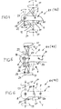
- FIGS. 4 to 6 illustrate various embodiments of the forced adjustment device V of the first rotary rake R1, wherein the tines and the tine control device have been omitted for the sake of clarity.
- the transmission housing 8 is incorporated in the main drawbar H, in the Distance from the pull point P for the drawbar Z is located.
- a defining the gyro axis Shaft 19 passes through the gear housing and is connected to the support frame 12 of the Chassis F1 rotatably connected.
- the support frame 12 of the chassis F1 holds the Wheels 11.
- With the shaft 19 is also the only schematically indicated tine control device 23 functionally coupled.
- On the shaft 19 is a lever 22nd attached to which a hydraulic cylinder 21 attacks, located on an abutment 20 of the main drawbar H is supported.
- the shaft 19 via the adjusting lever 22nd twisted (double arrow). This twist is transmitted to the support frame 12, to steer the wheels 11, and may also be applied to the tine control device 23 be transmitted.
- the forced-displacement device in FIG. 5 differs from that of FIG. 4 in that that the wheels 11 are mounted steerable on the support frame 12 (with steering joints 24, steering levers 25 and tie rods 26).
- the support frame 12 is either with the Main drawbar H or the transmission housing 8 firmly connected.
- the the gearbox 8 from top to bottom passing through shaft 19 is via an intermediate lever 27 coupled to the tie rods 26.
- the hydraulic cylinder 21, located on the abutment 20 is supported, engages the free end of the control lever 22 to depending on the application To steer the wheels 11 and to keep in the selected steering position. In this case, the tine control 23 can be adjusted accordingly.
- the support frame 12 of the wheels 11 is fixed to the transmission housing. 8 connected to a main drawbar end portion 28.
- the main drawbar end part 28 is bent in an articulated joint 29 with the main drawbar H connected (kink axis approximately perpendicular to the ground).
- the articulation 29 is close to the gyro axis or between the gyro axis and the traction point P for the drawbar Z positioned.
- the main drawbar H is over a hydraulic cylinder, which is supported directly on the tractor S, in the Ankupplungsstelle. 5 pivotable relative to the longitudinal center axis Y of the tractor S to the first rotary rake R1 to move laterally as desired and keep in the deflected position.
- the wheels could optionally be arranged self-steering.
- the second rotary rudder forcibly the tracking or manipulating the first rotary gyro can be followed by a sequencer be provided to direct the second rotary rake R2 as desired. This is explained with reference to FIG. 7.
- the wheels 11 'of the second rotary rake R2 are either directly steerable (analog to Fig. 5) or via the support frame 12 '(analogous to FIG. 4) or by means of a bendable drawbar end portion (analogous to FIG. 6). Another possibility exists therein, in the region of the draw point P between the main drawbar H and the drawbar Z to provide a hydraulic cylinder 16, with a desired bending angle adjustable and durable.
- the sequencer C has a steering command generator 14 on, for example, the bending angle between the main drawbar H and the Tractor S picks up and converts into steering commands.
- This steering command generator 14 may be a sensing lever which pivots in an abutment 15 on Main drawbar H and also pivotable on an abutment 13 of the tractor S is supported, and laterally from the towing connection 6 of the main drawbar H. Das respective steering command is transmitted via a signal transmission 18 to the steering device For example, the wheels 11 'transmitted.
- the steering command generator 14 e.g. a sensing lever, disposed at the position of the hydraulic cylinder 16 at the pull point P, to the bending angle between the main drawbar H and the drawbar Z to tap and convert into appropriate steering commands.
- the operator in the tractor S itself via a corresponding Control valve transmits a steering command to the wheels 11 'to these as desired to steer and to maneuver the second rotary rake R2.
- the hydraulic cylinder 16 could also be omitted, so that the second rotary rake R2 only by steering its wheels 11 'in the respective desired relative position the first rotary rake R1 and / or the tractor S can be set.
- Fig. 8 optical Einzelschwad position
- the drawbars H, Z relative to the direction of travel Angled in opposite directions, so that the rotary rakes R1, R2 equal width single swath ES shape, without that the zinc orbits 10, 10 'transverse to the direction of travel overlap significantly.
- the forced adjustment device V the main drawbar H to one side of the longitudinal center axis Y of the tractor S. inclined (by steering the wheels 11 of the rotary rake R1), while the Steering device L of the rotary rake R2 the drawbar Z to the other side at an angle has made (by steering the wheels 11 ').
Landscapes
- Life Sciences & Earth Sciences (AREA)
- Environmental Sciences (AREA)
- Soil Working Implements (AREA)
- Agricultural Machines (AREA)
- Harvester Elements (AREA)
- Handcart (AREA)
- Addition Polymer Or Copolymer, Post-Treatments, Or Chemical Modifications (AREA)
- Harvesting Machines For Specific Crops (AREA)
Applications Claiming Priority (2)
| Application Number | Priority Date | Filing Date | Title |
|---|---|---|---|
| DE202004008500U DE202004008500U1 (de) | 2004-05-28 | 2004-05-28 | Geschleppter Kreiselschwader |
| DE202004008500U | 2004-05-28 |
Publications (3)
| Publication Number | Publication Date |
|---|---|
| EP1600052A2 true EP1600052A2 (fr) | 2005-11-30 |
| EP1600052A3 EP1600052A3 (fr) | 2006-02-15 |
| EP1600052B1 EP1600052B1 (fr) | 2007-10-31 |
Family
ID=34936051
Family Applications (1)
| Application Number | Title | Priority Date | Filing Date |
|---|---|---|---|
| EP05009622A Expired - Lifetime EP1600052B1 (fr) | 2004-05-28 | 2005-05-02 | Andaineuse rotative remorquée |
Country Status (3)
| Country | Link |
|---|---|
| EP (1) | EP1600052B1 (fr) |
| AT (1) | ATE376766T1 (fr) |
| DE (2) | DE202004008500U1 (fr) |
Cited By (2)
| Publication number | Priority date | Publication date | Assignee | Title |
|---|---|---|---|---|
| CN117399289A (zh) * | 2023-11-22 | 2024-01-16 | 广东良友科技有限公司 | 一种机器视觉的led支架缺陷检测工艺 |
| EP4566439A1 (fr) * | 2023-12-05 | 2025-06-11 | Kverneland Group Kerteminde AS | Système et procédé de commande de direction d'un andaineur latéral remorqué |
Families Citing this family (1)
| Publication number | Priority date | Publication date | Assignee | Title |
|---|---|---|---|---|
| DE102009034422A1 (de) * | 2009-07-23 | 2011-02-03 | Kverneland Asa | Kreiselschwader |
Family Cites Families (6)
| Publication number | Priority date | Publication date | Assignee | Title |
|---|---|---|---|---|
| DE8908404U1 (de) * | 1989-07-10 | 1989-08-31 | Wilhelm Stoll Maschinenfabrik Gmbh, 3325 Lengede | Heuwerbungsmaschine |
| FR2756137B1 (fr) * | 1996-11-26 | 1999-01-22 | Kuhn Sa | Machine de fenaison, notamment une andaineuse avec un deflecteur d'andainage reglage automatiquement dans differentes positions |
| NL1006116C1 (nl) * | 1997-04-08 | 1998-10-09 | Maasland Nv | Inrichting voor het verplaatsen van zich op de grond bevindend gewas. |
| DE29806999U1 (de) * | 1998-04-17 | 1998-07-23 | Multinorm B.V., Nieuw-Vennep | Heuwerbungsmaschine |
| DE19928219A1 (de) * | 1999-06-19 | 2001-01-11 | Niemeyer Landmasch Gmbh | Heuwerbungsmaschine, insbesondere Kreiselschwader |
| DE10017967A1 (de) * | 2000-04-12 | 2001-10-18 | Claas Saulgau Gmbh | Heuwerbungsmaschine |
-
2004
- 2004-05-28 DE DE202004008500U patent/DE202004008500U1/de not_active Expired - Lifetime
-
2005
- 2005-05-02 EP EP05009622A patent/EP1600052B1/fr not_active Expired - Lifetime
- 2005-05-02 DE DE502005001805T patent/DE502005001805D1/de not_active Expired - Lifetime
- 2005-05-02 AT AT05009622T patent/ATE376766T1/de active
Cited By (2)
| Publication number | Priority date | Publication date | Assignee | Title |
|---|---|---|---|---|
| CN117399289A (zh) * | 2023-11-22 | 2024-01-16 | 广东良友科技有限公司 | 一种机器视觉的led支架缺陷检测工艺 |
| EP4566439A1 (fr) * | 2023-12-05 | 2025-06-11 | Kverneland Group Kerteminde AS | Système et procédé de commande de direction d'un andaineur latéral remorqué |
Also Published As
| Publication number | Publication date |
|---|---|
| ATE376766T1 (de) | 2007-11-15 |
| DE202004008500U1 (de) | 2005-10-06 |
| DE502005001805D1 (de) | 2007-12-13 |
| EP1600052A3 (fr) | 2006-02-15 |
| EP1600052B1 (fr) | 2007-10-31 |
Similar Documents
| Publication | Publication Date | Title |
|---|---|---|
| EP0316896B1 (fr) | Machine de fenaison | |
| DE2858680C2 (fr) | ||
| DE4206504C2 (de) | Heuwerbungsmaschine | |
| EP4101275B1 (fr) | Appareil accessoire destiné au traitement du sol | |
| EP2277370B1 (fr) | Andain gyroscopique | |
| EP0455022B1 (fr) | Machine de fenaison | |
| EP0950347B1 (fr) | Machine de fenaison | |
| EP1600052B1 (fr) | Andaineuse rotative remorquée | |
| DE602005005143T2 (de) | Heuwerbungsmaschine | |
| DE20010547U1 (de) | Heuwerbungsmaschine, insbesondere Kreiselschwader | |
| DE69604317T2 (de) | Heuwerbungsmaschine | |
| DE10330381B4 (de) | Heuwerbungsmaschine | |
| EP4490995B1 (fr) | Procédé de fonctionnement d'un attelage agricole | |
| DE102014208071B4 (de) | Zwischen einer Betriebs- und einer Transportstellung verstellbares landwirtschaftliches Arbeitsgerät | |
| EP3735818B1 (fr) | Engin agricole | |
| DE20004538U1 (de) | Heuwerbungsmaschine | |
| DE102006042552A1 (de) | Kreiselschwader | |
| DE10327883B4 (de) | Heuwerbungsmaschine | |
| DE10327705B3 (de) | Heuwerbungsmaschine | |
| EP1488681A1 (fr) | Machine de fenaison | |
| DE4331311A1 (de) | Kreiselzettwender | |
| DE1927495C (de) | Heuwerbungsmaschine | |
| DE1482216C (de) | Hangsteuervorrichtung fur landwirt schaftliche Maschinen, insbesondere Hack fruchterntemaschinen | |
| DE20221187U1 (de) | Kreiselschwader | |
| DE1482216B1 (de) | Hangsteuervorrichtung fuer landwirtschaftliche Maschinen,insbesondere Hackfruchterntemaschinen |
Legal Events
| Date | Code | Title | Description |
|---|---|---|---|
| PUAI | Public reference made under article 153(3) epc to a published international application that has entered the european phase |
Free format text: ORIGINAL CODE: 0009012 |
|
| AK | Designated contracting states |
Kind code of ref document: A2 Designated state(s): AT BE BG CH CY CZ DE DK EE ES FI FR GB GR HU IE IS IT LI LT LU MC NL PL PT RO SE SI SK TR |
|
| AX | Request for extension of the european patent |
Extension state: AL BA HR LV MK YU |
|
| PUAL | Search report despatched |
Free format text: ORIGINAL CODE: 0009013 |
|
| AK | Designated contracting states |
Kind code of ref document: A3 Designated state(s): AT BE BG CH CY CZ DE DK EE ES FI FR GB GR HU IE IS IT LI LT LU MC NL PL PT RO SE SI SK TR |
|
| AX | Request for extension of the european patent |
Extension state: AL BA HR LV MK YU |
|
| 17P | Request for examination filed |
Effective date: 20060816 |
|
| AKX | Designation fees paid |
Designated state(s): AT BE BG CH CY CZ DE DK EE ES FI FR GB GR HU IE IS IT LI LT LU MC NL PL PT RO SE SI SK TR |
|
| GRAP | Despatch of communication of intention to grant a patent |
Free format text: ORIGINAL CODE: EPIDOSNIGR1 |
|
| GRAS | Grant fee paid |
Free format text: ORIGINAL CODE: EPIDOSNIGR3 |
|
| GRAA | (expected) grant |
Free format text: ORIGINAL CODE: 0009210 |
|
| AK | Designated contracting states |
Kind code of ref document: B1 Designated state(s): AT BE BG CH CY CZ DE DK EE ES FI FR GB GR HU IE IS IT LI LT LU MC NL PL PT RO SE SI SK TR |
|
| REG | Reference to a national code |
Ref country code: GB Ref legal event code: FG4D Free format text: NOT ENGLISH |
|
| REG | Reference to a national code |
Ref country code: IE Ref legal event code: FG4D Free format text: LANGUAGE OF EP DOCUMENT: GERMAN |
|
| REG | Reference to a national code |
Ref country code: CH Ref legal event code: EP |
|
| REF | Corresponds to: |
Ref document number: 502005001805 Country of ref document: DE Date of ref document: 20071213 Kind code of ref document: P |
|
| NLV1 | Nl: lapsed or annulled due to failure to fulfill the requirements of art. 29p and 29m of the patents act | ||
| PG25 | Lapsed in a contracting state [announced via postgrant information from national office to epo] |
Ref country code: NL Free format text: LAPSE BECAUSE OF FAILURE TO SUBMIT A TRANSLATION OF THE DESCRIPTION OR TO PAY THE FEE WITHIN THE PRESCRIBED TIME-LIMIT Effective date: 20071031 Ref country code: ES Free format text: LAPSE BECAUSE OF FAILURE TO SUBMIT A TRANSLATION OF THE DESCRIPTION OR TO PAY THE FEE WITHIN THE PRESCRIBED TIME-LIMIT Effective date: 20080211 Ref country code: SE Free format text: LAPSE BECAUSE OF FAILURE TO SUBMIT A TRANSLATION OF THE DESCRIPTION OR TO PAY THE FEE WITHIN THE PRESCRIBED TIME-LIMIT Effective date: 20080131 |
|
| GBV | Gb: ep patent (uk) treated as always having been void in accordance with gb section 77(7)/1977 [no translation filed] | ||
| PG25 | Lapsed in a contracting state [announced via postgrant information from national office to epo] |
Ref country code: SI Free format text: LAPSE BECAUSE OF FAILURE TO SUBMIT A TRANSLATION OF THE DESCRIPTION OR TO PAY THE FEE WITHIN THE PRESCRIBED TIME-LIMIT Effective date: 20071031 Ref country code: PT Free format text: LAPSE BECAUSE OF FAILURE TO SUBMIT A TRANSLATION OF THE DESCRIPTION OR TO PAY THE FEE WITHIN THE PRESCRIBED TIME-LIMIT Effective date: 20080331 Ref country code: PL Free format text: LAPSE BECAUSE OF FAILURE TO SUBMIT A TRANSLATION OF THE DESCRIPTION OR TO PAY THE FEE WITHIN THE PRESCRIBED TIME-LIMIT Effective date: 20071031 Ref country code: LT Free format text: LAPSE BECAUSE OF FAILURE TO SUBMIT A TRANSLATION OF THE DESCRIPTION OR TO PAY THE FEE WITHIN THE PRESCRIBED TIME-LIMIT Effective date: 20071031 Ref country code: IS Free format text: LAPSE BECAUSE OF FAILURE TO SUBMIT A TRANSLATION OF THE DESCRIPTION OR TO PAY THE FEE WITHIN THE PRESCRIBED TIME-LIMIT Effective date: 20080229 Ref country code: BG Free format text: LAPSE BECAUSE OF FAILURE TO SUBMIT A TRANSLATION OF THE DESCRIPTION OR TO PAY THE FEE WITHIN THE PRESCRIBED TIME-LIMIT Effective date: 20080131 |
|
| REG | Reference to a national code |
Ref country code: IE Ref legal event code: FD4D |
|
| ET | Fr: translation filed | ||
| PG25 | Lapsed in a contracting state [announced via postgrant information from national office to epo] |
Ref country code: CZ Free format text: LAPSE BECAUSE OF FAILURE TO SUBMIT A TRANSLATION OF THE DESCRIPTION OR TO PAY THE FEE WITHIN THE PRESCRIBED TIME-LIMIT Effective date: 20071031 Ref country code: DK Free format text: LAPSE BECAUSE OF FAILURE TO SUBMIT A TRANSLATION OF THE DESCRIPTION OR TO PAY THE FEE WITHIN THE PRESCRIBED TIME-LIMIT Effective date: 20071031 |
|
| PG25 | Lapsed in a contracting state [announced via postgrant information from national office to epo] |
Ref country code: SK Free format text: LAPSE BECAUSE OF FAILURE TO SUBMIT A TRANSLATION OF THE DESCRIPTION OR TO PAY THE FEE WITHIN THE PRESCRIBED TIME-LIMIT Effective date: 20071031 Ref country code: RO Free format text: LAPSE BECAUSE OF FAILURE TO SUBMIT A TRANSLATION OF THE DESCRIPTION OR TO PAY THE FEE WITHIN THE PRESCRIBED TIME-LIMIT Effective date: 20071031 |
|
| PLBE | No opposition filed within time limit |
Free format text: ORIGINAL CODE: 0009261 |
|
| STAA | Information on the status of an ep patent application or granted ep patent |
Free format text: STATUS: NO OPPOSITION FILED WITHIN TIME LIMIT |
|
| 26N | No opposition filed |
Effective date: 20080801 |
|
| PG25 | Lapsed in a contracting state [announced via postgrant information from national office to epo] |
Ref country code: IE Free format text: LAPSE BECAUSE OF FAILURE TO SUBMIT A TRANSLATION OF THE DESCRIPTION OR TO PAY THE FEE WITHIN THE PRESCRIBED TIME-LIMIT Effective date: 20071031 |
|
| PG25 | Lapsed in a contracting state [announced via postgrant information from national office to epo] |
Ref country code: GB Free format text: LAPSE BECAUSE OF FAILURE TO SUBMIT A TRANSLATION OF THE DESCRIPTION OR TO PAY THE FEE WITHIN THE PRESCRIBED TIME-LIMIT Effective date: 20071031 |
|
| BERE | Be: lapsed |
Owner name: KVERNELAND GROUP GOTTMADINGEN G.M.B.H. & CO. KG Effective date: 20080531 |
|
| PG25 | Lapsed in a contracting state [announced via postgrant information from national office to epo] |
Ref country code: MC Free format text: LAPSE BECAUSE OF NON-PAYMENT OF DUE FEES Effective date: 20080531 |
|
| PG25 | Lapsed in a contracting state [announced via postgrant information from national office to epo] |
Ref country code: GR Free format text: LAPSE BECAUSE OF FAILURE TO SUBMIT A TRANSLATION OF THE DESCRIPTION OR TO PAY THE FEE WITHIN THE PRESCRIBED TIME-LIMIT Effective date: 20080201 Ref country code: EE Free format text: LAPSE BECAUSE OF FAILURE TO SUBMIT A TRANSLATION OF THE DESCRIPTION OR TO PAY THE FEE WITHIN THE PRESCRIBED TIME-LIMIT Effective date: 20071031 |
|
| PG25 | Lapsed in a contracting state [announced via postgrant information from national office to epo] |
Ref country code: FI Free format text: LAPSE BECAUSE OF FAILURE TO SUBMIT A TRANSLATION OF THE DESCRIPTION OR TO PAY THE FEE WITHIN THE PRESCRIBED TIME-LIMIT Effective date: 20071031 |
|
| PG25 | Lapsed in a contracting state [announced via postgrant information from national office to epo] |
Ref country code: BE Free format text: LAPSE BECAUSE OF NON-PAYMENT OF DUE FEES Effective date: 20080531 |
|
| PG25 | Lapsed in a contracting state [announced via postgrant information from national office to epo] |
Ref country code: CY Free format text: LAPSE BECAUSE OF FAILURE TO SUBMIT A TRANSLATION OF THE DESCRIPTION OR TO PAY THE FEE WITHIN THE PRESCRIBED TIME-LIMIT Effective date: 20071031 |
|
| REG | Reference to a national code |
Ref country code: CH Ref legal event code: PL |
|
| PG25 | Lapsed in a contracting state [announced via postgrant information from national office to epo] |
Ref country code: CH Free format text: LAPSE BECAUSE OF NON-PAYMENT OF DUE FEES Effective date: 20090531 Ref country code: LI Free format text: LAPSE BECAUSE OF NON-PAYMENT OF DUE FEES Effective date: 20090531 |
|
| PG25 | Lapsed in a contracting state [announced via postgrant information from national office to epo] |
Ref country code: LU Free format text: LAPSE BECAUSE OF NON-PAYMENT OF DUE FEES Effective date: 20080502 Ref country code: HU Free format text: LAPSE BECAUSE OF FAILURE TO SUBMIT A TRANSLATION OF THE DESCRIPTION OR TO PAY THE FEE WITHIN THE PRESCRIBED TIME-LIMIT Effective date: 20080501 |
|
| PG25 | Lapsed in a contracting state [announced via postgrant information from national office to epo] |
Ref country code: TR Free format text: LAPSE BECAUSE OF FAILURE TO SUBMIT A TRANSLATION OF THE DESCRIPTION OR TO PAY THE FEE WITHIN THE PRESCRIBED TIME-LIMIT Effective date: 20071031 |
|
| PG25 | Lapsed in a contracting state [announced via postgrant information from national office to epo] |
Ref country code: IT Free format text: LAPSE BECAUSE OF NON-PAYMENT OF DUE FEES Effective date: 20080531 |
|
| REG | Reference to a national code |
Ref country code: FR Ref legal event code: PLFP Year of fee payment: 12 |
|
| REG | Reference to a national code |
Ref country code: FR Ref legal event code: PLFP Year of fee payment: 13 |
|
| REG | Reference to a national code |
Ref country code: FR Ref legal event code: PLFP Year of fee payment: 14 |
|
| P01 | Opt-out of the competence of the unified patent court (upc) registered |
Effective date: 20230525 |
|
| PGFP | Annual fee paid to national office [announced via postgrant information from national office to epo] |
Ref country code: DE Payment date: 20240521 Year of fee payment: 20 |
|
| PGFP | Annual fee paid to national office [announced via postgrant information from national office to epo] |
Ref country code: AT Payment date: 20240522 Year of fee payment: 20 |
|
| PGFP | Annual fee paid to national office [announced via postgrant information from national office to epo] |
Ref country code: FR Payment date: 20240529 Year of fee payment: 20 |
|
| REG | Reference to a national code |
Ref country code: DE Ref legal event code: R071 Ref document number: 502005001805 Country of ref document: DE |
|
| REG | Reference to a national code |
Ref country code: AT Ref legal event code: MK07 Ref document number: 376766 Country of ref document: AT Kind code of ref document: T Effective date: 20250502 |