EP1600086A1 - Machine à café éléctrique pour la production de café expresso - Google Patents
Machine à café éléctrique pour la production de café expresso Download PDFInfo
- Publication number
- EP1600086A1 EP1600086A1 EP05104356A EP05104356A EP1600086A1 EP 1600086 A1 EP1600086 A1 EP 1600086A1 EP 05104356 A EP05104356 A EP 05104356A EP 05104356 A EP05104356 A EP 05104356A EP 1600086 A1 EP1600086 A1 EP 1600086A1
- Authority
- EP
- European Patent Office
- Prior art keywords
- vessel
- coffee
- coffee maker
- lower vessel
- maker according
- Prior art date
- Legal status (The legal status is an assumption and is not a legal conclusion. Google has not performed a legal analysis and makes no representation as to the accuracy of the status listed.)
- Granted
Links
Images




Classifications
-
- A—HUMAN NECESSITIES
- A47—FURNITURE; DOMESTIC ARTICLES OR APPLIANCES; COFFEE MILLS; SPICE MILLS; SUCTION CLEANERS IN GENERAL
- A47J—KITCHEN EQUIPMENT; COFFEE MILLS; SPICE MILLS; APPARATUS FOR MAKING BEVERAGES
- A47J31/00—Apparatus for making beverages
- A47J31/24—Coffee-making apparatus in which hot water is passed through the filter under pressure, i.e. in which the coffee grounds are extracted under pressure
- A47J31/30—Coffee-making apparatus in which hot water is passed through the filter under pressure, i.e. in which the coffee grounds are extracted under pressure with hot water under steam pressure
- A47J31/303—Coffee-making apparatus in which hot water is passed through the filter under pressure, i.e. in which the coffee grounds are extracted under pressure with hot water under steam pressure classical type of espresso apparatus, e.g. to put on a stove, i.e. in which the water is heated in a lower, sealed boiling vessel, raised by the steam pressure through a rising pipe and an extraction chamber and subsequently is collected in a beverage container on top of the water boiling vessel
- A47J31/306—Coffee-making apparatus in which hot water is passed through the filter under pressure, i.e. in which the coffee grounds are extracted under pressure with hot water under steam pressure classical type of espresso apparatus, e.g. to put on a stove, i.e. in which the water is heated in a lower, sealed boiling vessel, raised by the steam pressure through a rising pipe and an extraction chamber and subsequently is collected in a beverage container on top of the water boiling vessel with integral electrical heating means
-
- A—HUMAN NECESSITIES
- A47—FURNITURE; DOMESTIC ARTICLES OR APPLIANCES; COFFEE MILLS; SPICE MILLS; SUCTION CLEANERS IN GENERAL
- A47J—KITCHEN EQUIPMENT; COFFEE MILLS; SPICE MILLS; APPARATUS FOR MAKING BEVERAGES
- A47J31/00—Apparatus for making beverages
- A47J31/44—Parts or details or accessories of beverage-making apparatus
- A47J31/4496—Means to produce beverage with a layer on top, e.g. of cream, foam or froth
Definitions
- the present invention relates to an electric coffee maker for the production of espresso coffee.
- the traditional coffee maker for domestic use is formed by a lower vessel and an upper vessel generally screwed axially and tightly one to the other and communicating via an intermediate, substantially funnel-shaped vessel having a tubular portion.
- An axial duct open at the upper end and if necessary provided with a dispensing member, extends from the base of the upper vessel.
- the coffee powder is placed in the intermediate vessel, while the lower vessel, which acts as a boiler, is filled with water as far as a preset level.
- the working pressure of the hot water that traverses the layer of coffee powder is generally very low and, since it is limited by a safety valve, the pressure drop through the layer of coffee powder cannot go beyond certain values.
- the low pressure of the hot water is responsible for the incomplete process of infusion whose effect influences the properties of the coffee produced.
- the pressure of the hot water inside the boiler is provided by a pump which feeds it over a filter filled with coffee powder and enclosed in a filter holder.
- the pressure of the water associated with the finer grain size of the powder and a smaller section of the holes of the filtering plate, allows a more intense infusion process whereby the substances contained in the coffee powder, which confer to the infusion the typical properties of espresso coffee, are almost completely extracted.
- the main object of the present invention is to provide a coffee maker for domestic use which has the structure of a moka coffee maker yet which enables coffee infusions to be made with the typical properties of espresso coffee.
- a particular object of the present invention is to provide a coffee maker of the type mentioned above which is small in size and, in any case, only slightly larger in size than a traditional moka coffee maker.
- Another object of the present invention is to provide a coffee maker of the type mentioned above which allows the production of several servings of espresso coffee.
- a further object of the present invention is to provide a coffee maker of the type mentioned above wherein the ordinary maintenance operations (washing of the boiler and coffee collecting vessel, and emptying the used coffee powder) are simple and fast and the risks of soiling for the user and worktops are minimised.
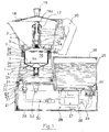
- the domestic coffee maker for producing espresso coffee comprises a lower vessel 1 or boiler, an intermediate, substantially funnel shaped vessel 2 suitable for holding the coffee powder and tightly connected to the boiler 1 at its inlet, and an upper vessel 3 for collecting the coffee infusion, arranged coaxially to the boiler 1 and to the intermediate vessel 2.
- the intermediate vessel 2 has a cylindrical portion 2a and a tubular portion 2b joined one to the other by a truncated cone portion 2c, the tubular portion 2b extending axially towards the bottom wall of the boiler 1.
- the inlet of the boiler 1 is defined by a tubular wall 1a whereto the cylindrical portion 2a is connected tightly by means of an O ring 60.
- a small perimetric edge 2d projecting from the cylindrical portion rests on the edge of the tubular wall 1a.
- a disk-shaped body 4 extends above the intermediate vessel 2 and is bordered around its perimeter by a sleeve edge 5 which is screwed externally to the tubular wall 1a.
- the disk 4 has a substantially conical shape slanting towards the upper vessel 3 above, and on the side of the intermediate vessel 2 holds a filtering plate 6 attached by means of an annular seal 7 engaged in a groove 8 formed on the internal face of the sleeve 5 immediately below the disk 4.
- a container 9 is placed, with a finely perforated base 9a which, together with the filtering plate 6, defines a chamber 10 for containing the coffee powder.
- the container for the coffee powder 9 has a small projecting perimeter edge 9b which is placed between the seal 7 and the corresponding small edge 2d of the intermediate vessel 2 when the sleeve 5 is completely screwed to the tubular wall 1a of the boiler 1, in this way securing the container 9 inside the intermediate vessel 2.
- An elastic element 11 is provided inside the truncated cone portion 2c of the intermediate vessel 2.
- the elastic element 11 is placed between the truncated cone walls of portion 2c and the bottom wall 9a of the coffee powder container 9.
- the elastic element 11 is compressed by the base 9a when the sleeve 5 is fully screwed to the tubular wall 1a, so that, when said sleeve is unscrewed and removed, the elastic reaction of the elastic element 11 pushes the container 9 axially, making it project partially from the intermediate vessel 2 and thus facilitating its grip for subsequent extraction and removal of the used coffee powder.
- raising of the container 9 creates a vacuum in the part below it which draws the water located between the disk 4 and the surface of the coffee powder. This water, mixed with coffee powder, would otherwise inevitably flow to the outside, when the disk-shaped body 4 is unscrewed from the lower vessel 1.
- a first tubular element 12 extends axially from the centre of the disk 4 inside the upper vessel 3 and a second tubular element 13, extending coaxially from the bottom wall 3a of the upper vessel 3, engages slidingly on the first tubular element 12.
- the base 3a rests on the disk 4, with the same configuration and slant, and along its perimeter a groove 14 is formed, wherein the tubular sleeve 5 engages, in this way removably securing the upper vessel 3 to the boiler 1.
- the tubular element 12 which extends from the disk 4, defines a duct 15 ending with a flared portion in which a truncated cone bush 16 is engaged, with the same slant, ending with a radially perforated head 16a through which the coffee produced can flow.
- a skirt 17 extends radially from the bush 16, immediately below its perforated head 16a, and around the tubular element 13 at its free end.
- the bush 16, forming a watertight connection with the tubular element 12 due to the conicity of the respective reciprocal contact walls, prevents infiltration of the coffee infusion between the upper vessel 3 and the disk 4, assisted for this purpose also by the skirt 17 which covers the free ends of the two tubular elements 12 and 13.
- the upper vessel 3 is provided, as is customary, with a lid 18, with a central knob 19 for its raising, and a side handle 20.
- the lower vessel 1 is mounted on a box-shaped body 21 provided with a removable base 22. More specifically the box-shaped body 21 has a raised portion 23 which engages in a corresponding cavity 24 formed on the base of the lower vessel 1.
- a water reservoir 25, with a removable lid 26, is also positioned on the box-shaped body 21, alongside the lower vessel 1.
- a pump 27 is placed, supported by elastic vibration-preventing supports 28 and connected to the reservoir 25 via a suction duct 29 and to the boiler 1 via a discharge duct 30.
- the connection between the duct 29 and the base of the reservoir 25 is formed by means of a valve 61 suitable for preventing the release of water from the reservoir when the latter is disengaged from the duct 29 so as to be removed from the box-shaped body 21, for example for cleaning.
- the discharge duct 30, in the present embodiment of the invention is instead connected to the boiler 1 via a fixed coupling joint 31, so that the boiler 1 is integral with the box-shaped body 21 and can be separated therefrom only by accessing its interior and adjusting a connection ring nut.
- the joint 31 is connected to a release nozzle 32 situated on the bottom wall of the boiler 1, wherefrom the cold water flows out, preferably tangentially to the base of the boiler so as to eliminate, or at least limit, turbulence phenomena.
- the water is heated by means of an electrical resistor 33 embedded in the metal of the boiler 1 on the bottom wall thereof and the temperature is controlled by means of a thermostat 52.
- the coffee maker according to the invention is also provided with a control panel, not shown, formed for example frontally on the box-shaped body 21 and provided with all the pushbuttons and the operation indicators required for operative control of the coffee maker.
- the chamber 10 When using the coffee maker according to the invention, after having filled with water the reservoir 25 and the boiler up to the level indicated therein, and after having placed the coffee powder in the container 9, the chamber 10 is closed by screwing the disk 4 to the boiler 1 and positioning the upper reservoir 3 above it.
- the heating device is then switched on and remains in operation until the temperature of the water has reached the preset value (generally around 95°C).
- the user by pressing the pushbutton for starting the pump 27, causes water to flow into the boiler 1 which forces the hot water into the tubular portion 2b, making it pass through the layer of coffee powder and from there rise up through the duct 15 until it flows out into the upper vessel 3.
- the user will keep the pump 27 in operation until the level in the upper vessel 2 has risen to the level corresponding to the servings required.
- the latter will be made of a transparent material and a scale indicating the servings which correspond to the level reached by the coffee infusion will be provided on the vessel wall.
- a valve 34 is placed inside the tubular portion 2b of the intermediate vessel 2, illustrated by way of an example in the form of a rubber ball forced elastically against the aperture for access to the tubular portion 2b. This valve avoids the pulsed feed of hot water at low pressure through the layer of coffee powder before the start of the pump.
- a further valve 35 is provided at the inlet of the duct 15 with the triple function of ensuring discharge of the coffee infusion only after the pressure in the chamber 10 has reached a preset value sufficient for providing an optimal water-powder contact time, of forming in the duct 15 an orifice with restricted section for causing turbulence in the flow of liquid and with formation of the typical cream of espresso coffee, and finally of preventing the residual coffee remaining in the duct 15 from flowing out therefrom when the coffee maker is disassembled for cleaning.
- valve 35 is considered essential for the multiple functions it is called on to perform
- the valve 34 is not strictly necessary for controlling the pressure inside the boiler. Although with a limited loss of working flexibility, this control too can be assigned to the valve 35. In this case the hot water gradually fills the intermediate vessel as the pump feeds cold water into the lower vessel and dispensing of the coffee infusion only starts when the pressure of the infusion above the coffee powder exceeds the calibration pressure of the valve 35.
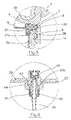
- Figures 4 and 5 show a variation of the coffee maker according to the invention.
- the variation illustrated in Figures 4 and 5 relates to the intermediate vessel 2 which, in this case, is housed removably in a freely sliding manner in the inlet opening of the boiler 1 and is not provided with the container 9 for the coffee powder, but has an evenly perforated plate 36 on which the coffee powder is placed directly.
- the seal 7 has an axial edge 37 extending inside the cylindrical portion 2a of the second vessel 2 and ending with an enlargement 37a which engages in a groove 38 formed on the wall of the cylindrical portion 2a.
- the intermediate vessel 2 is also extracted simultaneously from the boiler 1 with its content of used coffee powder. Once extracted from the boiler 2, it is easy to separate the intermediate vessel 2 from the seal 7 by a slight traction, in order to proceed subsequently with its emptying and washing. In addition to allowing easy removal of the intermediate vessel, with this solution too the leakage of liquid mixed with coffee powder is avoided when unscrewing the disk-shaped body 4 due to the vacuum created by raising of the intermediate vessel 2.
- FIG. 6 illustrates an example of coupling connection joint which allows the boiler 1 to be separated from the body 21 whenever required, for example for cleaning of the boiler, and which can be used as an alternative to a fixed coupling.
- a valve 40 is provided which intercepts the exit of a tubular element 41, at the entrance whereof the discharge duct 30 of the pump is connected and which is fixed thereon by means of a tightening screw nut 42 screwed to the body of the tubular element 41.
- the latter is attached, for example screwed, to the raised portion 23 of the base 21 in a special housing 23a formed thereon.
- the tubular element 41 is tightly coupled in a housing 43 formed on the base 39 at the valve 40.
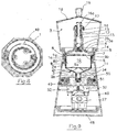
- FIGS 7, 8 and 9 illustrate a second embodiment of the coffee maker according to the invention wherein components identical to those present in the first embodiment previously described and illustrated have the same reference numerals.
- the pump 27 is housed in a box-shaped body 46 integral with the lower vessel 1 and rests on a base 48 on which the reservoir 25 also rests.
- the pump 27 is mounted on vibration-preventing supports 28 and is connected to the reservoir 25 via a suction duct 29 and to the boiler 1 via a discharge duct 30.
- the discharge duct 30, in the present embodiment of the invention flows into a spiral path 49 formed on the base of the boiler 1, which can be seen in particular in Figure 8, and forming part of a known and so-called "Thermoblock" device, denoted by 50, formed by armoured and co-moulded resistors 51 embedded in the metal of the boiler 1 and extending above the spiral path 49.
- a pair of thermostats 52 are provided on the base of the boiler 1 to control the temperature of the water which in this case reaches almost instantaneously its optimal value while passing in the spiral duct 49 and then the production of coffee can begin automatically once the boiler 1 is filled.
- a rapid electrical connection generally indicated at 53 in figure 7, known commercially by the name STRIX, which, since it is well known in the sector of small electric household appliances, is not illustrated in further detail.
- the actual coffee maker with associated box-shaped body 46 can be separated from the reservoir 25 and from the base 48 whenever necessary, for example in order to remove the used coffee powder, allowing performance of the operation for example over the sink in order not to soil the worktop with sprays of water which inevitably come out of the boiler when it is separated from the disk 4.
- the pump 27 for feeding water to the boiler 1 is housed in a cavity 55 formed in the lower part of the water reservoir 25 and its suction and discharge ducts 29 and 30 are connected in a fixed manner to the reservoir 25 and to the boiler 1 respectively.
- the base 48 contains only the electrical part of the appliance and the electrical connector 53, of the STRIX type, and can be separated from the rest of the appliance. In this solution the reservoir 25 surrounds the boiler 1, in this way recovering the volume lost due to the cavity 55.
- the heating device provided in one of the embodiments described and illustrated above can alternatively be used also in the other embodiments, and different heating devices and means from those illustrated can be used, provided they are functionally equivalent.
Landscapes
- Engineering & Computer Science (AREA)
- Food Science & Technology (AREA)
- Apparatus For Making Beverages (AREA)
- Tea And Coffee (AREA)
Applications Claiming Priority (2)
| Application Number | Priority Date | Filing Date | Title |
|---|---|---|---|
| IT000121A ITFI20040121A1 (it) | 2004-05-28 | 2004-05-28 | Caffetteria elettrica per la produzione di caffe' espresso |
| ITFI20040121 | 2004-05-28 |
Publications (2)
| Publication Number | Publication Date |
|---|---|
| EP1600086A1 true EP1600086A1 (fr) | 2005-11-30 |
| EP1600086B1 EP1600086B1 (fr) | 2007-06-27 |
Family
ID=34939936
Family Applications (1)
| Application Number | Title | Priority Date | Filing Date |
|---|---|---|---|
| EP05104356A Expired - Lifetime EP1600086B1 (fr) | 2004-05-28 | 2005-05-23 | Machine à café éléctrique pour la production de café expresso |
Country Status (5)
| Country | Link |
|---|---|
| US (1) | US20050268790A1 (fr) |
| EP (1) | EP1600086B1 (fr) |
| AT (1) | ATE365494T1 (fr) |
| DE (1) | DE602005001467D1 (fr) |
| IT (1) | ITFI20040121A1 (fr) |
Cited By (9)
| Publication number | Priority date | Publication date | Assignee | Title |
|---|---|---|---|---|
| WO2010006953A1 (fr) * | 2008-07-14 | 2010-01-21 | Nestec S.A. | Système de circulation d'eau pour un dispositif de préparation de boissons |
| US8733230B2 (en) | 2008-05-28 | 2014-05-27 | Nestec S.A. | Pump for liquid beverage preparation devices |
| RU2553196C2 (ru) * | 2010-01-06 | 2015-06-10 | Нестек С.А. | Безвибрационный резервуар для воды аппарата для приготовления напитков |
| CN106724821A (zh) * | 2016-12-12 | 2017-05-31 | 慈溪欧能电器有限公司 | 一种便携式咖啡机 |
| WO2017176517A1 (fr) | 2016-04-05 | 2017-10-12 | Mancini Graziano | Infuseur de boisson |
| EP3431109A1 (fr) * | 2017-03-30 | 2019-01-23 | Daniel Hector Franco Marin | Dispositif de désinfection d'objets |
| EP3501344A1 (fr) * | 2017-12-05 | 2019-06-26 | Trentino Erbe di Tondin Florenza | Dispositif de préparation de boissons par infusion |
| IT202100002681A1 (it) * | 2021-02-08 | 2022-08-08 | Carlo Freddie Galimberti | Dispositivo per generare crema o schiuma di caffè inserito in una caffettiera del tipo moka |
| IT202100013943A1 (it) * | 2021-05-27 | 2022-11-27 | Verdianelli Valentina | Sistema per la preparazione del caffè |
Families Citing this family (16)
| Publication number | Priority date | Publication date | Assignee | Title |
|---|---|---|---|---|
| JP3921226B2 (ja) * | 2005-07-29 | 2007-05-30 | シャープ株式会社 | 加熱調理器 |
| DE502007002027D1 (de) * | 2007-01-24 | 2009-12-31 | Wmf Wuerttemberg Metallwaren | Maschine mit automatisch abgedichteter Brühkammer |
| IT1393999B1 (it) * | 2009-04-01 | 2012-05-17 | Rancilio Macchine Caffe | Macchina per la preparazione di infusi, in particolare caffe' espresso, gruppo erogatore e metodo di realizzazione della stessa |
| US10441105B1 (en) | 2009-09-28 | 2019-10-15 | Leslie William Fogg, IV | Portable drinking vessel and automatic beverage brewing device |
| US8584576B2 (en) * | 2009-09-28 | 2013-11-19 | Leslie William Fogg, IV | Portable automatic beverage brewing drinking vessel |
| US20110174168A1 (en) * | 2010-01-21 | 2011-07-21 | AMF Automation Technologies, LLC d/b/a AMF Bakery Systems | Dough Pump and Developer |
| KR20160005706A (ko) * | 2013-04-11 | 2016-01-15 | 옥스 프로덕츠 엘엘씨 | 휴대 가능한 커피 브루어 |
| US11589700B2 (en) * | 2015-11-09 | 2023-02-28 | Conair Llc | Food steamer |
| IT201700050633A1 (it) * | 2017-05-10 | 2017-08-10 | Mauro Tafuri | Dispositivo amovibile dotato di una caffettiera tipo moka o di una caffettiera tipo napoletana e relativo procedimento di preparazione di una bevanda di caffè |
| WO2021029685A1 (fr) * | 2019-08-13 | 2021-02-18 | 이건호 | Dispositif d'extraction d'expresso |
| KR102393821B1 (ko) * | 2019-08-13 | 2022-05-04 | 이건호 | 에스프레소 추출장치 |
| GB2590904B (en) | 2019-12-16 | 2023-05-03 | Giocoguado Ltd | Coffee-making apparatus, valve and adapter plate |
| WO2021151093A1 (fr) * | 2020-01-23 | 2021-07-29 | Bunn-O-Matic Corporation | Système de chauffe-eau à réservoirs multiples |
| KR102594064B1 (ko) * | 2021-09-27 | 2023-10-24 | 경윤현 | 설정온도에서의 구동되는 비전기식 커피 추출기구 |
| KR102599604B1 (ko) * | 2021-11-11 | 2023-11-07 | 정상준 | 커피 추출 장치 |
| EP4640117A1 (fr) * | 2024-04-24 | 2025-10-29 | Simone Previati | Dispositif pour préparer du café ou d'autres boissons |
Citations (1)
| Publication number | Priority date | Publication date | Assignee | Title |
|---|---|---|---|---|
| EP1388313A2 (fr) * | 2002-08-06 | 2004-02-11 | Strix Limited | Récipient électrique à confectionner des breuvages |
Family Cites Families (9)
| Publication number | Priority date | Publication date | Assignee | Title |
|---|---|---|---|---|
| US3077156A (en) * | 1957-11-12 | 1963-02-12 | Egi Mario | Percolator |
| US3670641A (en) * | 1969-12-31 | 1972-06-20 | Luciano Mancioli | Beverage infusion apparatus, for example coffee |
| US4498375A (en) * | 1984-03-01 | 1985-02-12 | Dante Bedini | Automatic coffee pot |
| CH683818A5 (de) * | 1992-02-20 | 1994-05-31 | Lacrex Sa | Vorrichtung zum Bereiten heisser Getränke. |
| IT1287771B1 (it) * | 1996-10-10 | 1998-08-18 | Caffe Molinari S P A | Macchinetta tipo moka, per il caffe' espresso o per altre bevande analoghe |
| US5970850A (en) * | 1997-09-03 | 1999-10-26 | Piazza; Pietro | Coffee, tea and herbal tea maker |
| GB0103658D0 (en) * | 2001-02-14 | 2001-03-28 | Strix Ltd | Electric beverage maker |
| US6701826B2 (en) * | 2002-06-28 | 2004-03-09 | Eupa International Corporation | Electric coffee maker for selectively brewing Espresso coffee and Americano coffee |
| US6823771B2 (en) * | 2002-10-08 | 2004-11-30 | Pietro Piazza | Coffee, tea, and herbal tea maker |
-
2004
- 2004-05-28 IT IT000121A patent/ITFI20040121A1/it unknown
-
2005
- 2005-05-23 EP EP05104356A patent/EP1600086B1/fr not_active Expired - Lifetime
- 2005-05-23 DE DE602005001467T patent/DE602005001467D1/de not_active Expired - Lifetime
- 2005-05-23 AT AT05104356T patent/ATE365494T1/de not_active IP Right Cessation
- 2005-05-28 US US11/146,760 patent/US20050268790A1/en not_active Abandoned
Patent Citations (1)
| Publication number | Priority date | Publication date | Assignee | Title |
|---|---|---|---|---|
| EP1388313A2 (fr) * | 2002-08-06 | 2004-02-11 | Strix Limited | Récipient électrique à confectionner des breuvages |
Cited By (15)
| Publication number | Priority date | Publication date | Assignee | Title |
|---|---|---|---|---|
| US8733230B2 (en) | 2008-05-28 | 2014-05-27 | Nestec S.A. | Pump for liquid beverage preparation devices |
| AU2009272908B2 (en) * | 2008-07-14 | 2015-06-25 | Nestec S.A. | Water circulation system for a beverage preparation device |
| RU2506876C2 (ru) * | 2008-07-14 | 2014-02-20 | Нестек С.А. | Система циркуляции воды в устройстве для приготовления напитков |
| CN102088891B (zh) * | 2008-07-14 | 2014-02-26 | 雀巢产品技术援助有限公司 | 饮料制备装置的水循环系统 |
| CN102088891A (zh) * | 2008-07-14 | 2011-06-08 | 雀巢产品技术援助有限公司 | 饮料制备装置的水循环系统 |
| WO2010006953A1 (fr) * | 2008-07-14 | 2010-01-21 | Nestec S.A. | Système de circulation d'eau pour un dispositif de préparation de boissons |
| RU2553196C2 (ru) * | 2010-01-06 | 2015-06-10 | Нестек С.А. | Безвибрационный резервуар для воды аппарата для приготовления напитков |
| WO2017176517A1 (fr) | 2016-04-05 | 2017-10-12 | Mancini Graziano | Infuseur de boisson |
| EP3439510A4 (fr) * | 2016-04-05 | 2019-11-13 | Longo, Stephen A. | Infuseur de boisson |
| CN106724821A (zh) * | 2016-12-12 | 2017-05-31 | 慈溪欧能电器有限公司 | 一种便携式咖啡机 |
| CN106724821B (zh) * | 2016-12-12 | 2023-09-12 | 慈溪欧能电器有限公司 | 一种便携式咖啡机 |
| EP3431109A1 (fr) * | 2017-03-30 | 2019-01-23 | Daniel Hector Franco Marin | Dispositif de désinfection d'objets |
| EP3501344A1 (fr) * | 2017-12-05 | 2019-06-26 | Trentino Erbe di Tondin Florenza | Dispositif de préparation de boissons par infusion |
| IT202100002681A1 (it) * | 2021-02-08 | 2022-08-08 | Carlo Freddie Galimberti | Dispositivo per generare crema o schiuma di caffè inserito in una caffettiera del tipo moka |
| IT202100013943A1 (it) * | 2021-05-27 | 2022-11-27 | Verdianelli Valentina | Sistema per la preparazione del caffè |
Also Published As
| Publication number | Publication date |
|---|---|
| DE602005001467D1 (de) | 2007-08-09 |
| US20050268790A1 (en) | 2005-12-08 |
| EP1600086B1 (fr) | 2007-06-27 |
| ITFI20040121A1 (it) | 2004-08-28 |
| ATE365494T1 (de) | 2007-07-15 |
Similar Documents
| Publication | Publication Date | Title |
|---|---|---|
| EP1600086B1 (fr) | Machine à café éléctrique pour la production de café expresso | |
| US4565121A (en) | Apparatus for use in preparing infusions | |
| US12538997B2 (en) | Cleaning system and method for beverage appliance | |
| EP1020152B1 (fr) | Machine pour faire du thé | |
| US6405637B1 (en) | Fluid delivery system for generating pressure pulses to make beverages | |
| US5046409A (en) | Machine for brewing hot beverages | |
| EP0231156B1 (fr) | Machine à café à actionnement manuel | |
| US4945824A (en) | Cappuccino making adapter for use with coffee makers | |
| EP1658796B1 (fr) | Machine à café et procédé de préparation d'une boisson chaude | |
| JP6835845B2 (ja) | コーヒーメーカおよびコーヒーメーカを運転する方法 | |
| EP1522243A2 (fr) | Dispositif d'étanchéité d'une machine à café | |
| US20090202691A1 (en) | Coffee making apparatus and method | |
| US9259116B2 (en) | Stove top device for making espresso coffee | |
| CN107072421A (zh) | 单杯饮料咖啡机和使用该单杯饮料咖啡机的方法 | |
| CN101742918A (zh) | 便携沏煮装置及其制造和操作方法 | |
| EP2109386B1 (fr) | Structure de cafetière pour la préparation de boissons chaudes | |
| CA2482115A1 (fr) | Support a dosette et accessoire a mousser pour cafetiere | |
| US3092012A (en) | Brewing apparatus for coffee maker | |
| US4599937A (en) | Machine for making espresso coffee, particularly for domestic use | |
| US8127665B2 (en) | Apparatus for preparing a coffee beverage | |
| CN217161768U (zh) | 一种分体式电热咖啡壶 | |
| RU2462976C2 (ru) | Кофемашина для приготовления кофе эспрессо с устройством предварительного настаивания | |
| KR20200002263U (ko) | 음료 추출장치 | |
| CN116236057B (zh) | 一种茶叶及茶制品的分离式冲泡装置 | |
| CN2664541Y (zh) | 饮料调制机 |
Legal Events
| Date | Code | Title | Description |
|---|---|---|---|
| PUAI | Public reference made under article 153(3) epc to a published international application that has entered the european phase |
Free format text: ORIGINAL CODE: 0009012 |
|
| AK | Designated contracting states |
Kind code of ref document: A1 Designated state(s): AT BE BG CH CY CZ DE DK EE ES FI FR GB GR HU IE IS IT LI LT LU MC NL PL PT RO SE SI SK TR |
|
| AX | Request for extension of the european patent |
Extension state: AL BA HR LV MK YU |
|
| 17P | Request for examination filed |
Effective date: 20060509 |
|
| AKX | Designation fees paid |
Designated state(s): AT BE BG CH CY CZ DE DK EE ES FI FR GB GR HU IE IS IT LI LT LU MC NL PL PT RO SE SI SK TR |
|
| GRAP | Despatch of communication of intention to grant a patent |
Free format text: ORIGINAL CODE: EPIDOSNIGR1 |
|
| GRAS | Grant fee paid |
Free format text: ORIGINAL CODE: EPIDOSNIGR3 |
|
| GRAA | (expected) grant |
Free format text: ORIGINAL CODE: 0009210 |
|
| AK | Designated contracting states |
Kind code of ref document: B1 Designated state(s): AT BE BG CH CY CZ DE DK EE ES FI FR GB GR HU IE IS IT LI LT LU MC NL PL PT RO SE SI SK TR |
|
| REG | Reference to a national code |
Ref country code: GB Ref legal event code: FG4D |
|
| REG | Reference to a national code |
Ref country code: CH Ref legal event code: EP |
|
| REG | Reference to a national code |
Ref country code: IE Ref legal event code: FG4D |
|
| REF | Corresponds to: |
Ref document number: 602005001467 Country of ref document: DE Date of ref document: 20070809 Kind code of ref document: P |
|
| PG25 | Lapsed in a contracting state [announced via postgrant information from national office to epo] |
Ref country code: SE Free format text: LAPSE BECAUSE OF FAILURE TO SUBMIT A TRANSLATION OF THE DESCRIPTION OR TO PAY THE FEE WITHIN THE PRESCRIBED TIME-LIMIT Effective date: 20070927 |
|
| PG25 | Lapsed in a contracting state [announced via postgrant information from national office to epo] |
Ref country code: PL Free format text: LAPSE BECAUSE OF FAILURE TO SUBMIT A TRANSLATION OF THE DESCRIPTION OR TO PAY THE FEE WITHIN THE PRESCRIBED TIME-LIMIT Effective date: 20070627 Ref country code: AT Free format text: LAPSE BECAUSE OF FAILURE TO SUBMIT A TRANSLATION OF THE DESCRIPTION OR TO PAY THE FEE WITHIN THE PRESCRIBED TIME-LIMIT Effective date: 20070627 |
|
| NLV1 | Nl: lapsed or annulled due to failure to fulfill the requirements of art. 29p and 29m of the patents act | ||
| REG | Reference to a national code |
Ref country code: CH Ref legal event code: PL |
|
| PG25 | Lapsed in a contracting state [announced via postgrant information from national office to epo] |
Ref country code: BE Free format text: LAPSE BECAUSE OF FAILURE TO SUBMIT A TRANSLATION OF THE DESCRIPTION OR TO PAY THE FEE WITHIN THE PRESCRIBED TIME-LIMIT Effective date: 20070627 |
|
| PG25 | Lapsed in a contracting state [announced via postgrant information from national office to epo] |
Ref country code: PT Free format text: LAPSE BECAUSE OF FAILURE TO SUBMIT A TRANSLATION OF THE DESCRIPTION OR TO PAY THE FEE WITHIN THE PRESCRIBED TIME-LIMIT Effective date: 20071127 Ref country code: ES Free format text: LAPSE BECAUSE OF FAILURE TO SUBMIT A TRANSLATION OF THE DESCRIPTION OR TO PAY THE FEE WITHIN THE PRESCRIBED TIME-LIMIT Effective date: 20071008 Ref country code: SI Free format text: LAPSE BECAUSE OF FAILURE TO SUBMIT A TRANSLATION OF THE DESCRIPTION OR TO PAY THE FEE WITHIN THE PRESCRIBED TIME-LIMIT Effective date: 20070627 Ref country code: BG Free format text: LAPSE BECAUSE OF FAILURE TO SUBMIT A TRANSLATION OF THE DESCRIPTION OR TO PAY THE FEE WITHIN THE PRESCRIBED TIME-LIMIT Effective date: 20070927 Ref country code: LT Free format text: LAPSE BECAUSE OF FAILURE TO SUBMIT A TRANSLATION OF THE DESCRIPTION OR TO PAY THE FEE WITHIN THE PRESCRIBED TIME-LIMIT Effective date: 20070627 Ref country code: IS Free format text: LAPSE BECAUSE OF FAILURE TO SUBMIT A TRANSLATION OF THE DESCRIPTION OR TO PAY THE FEE WITHIN THE PRESCRIBED TIME-LIMIT Effective date: 20071027 Ref country code: NL Free format text: LAPSE BECAUSE OF FAILURE TO SUBMIT A TRANSLATION OF THE DESCRIPTION OR TO PAY THE FEE WITHIN THE PRESCRIBED TIME-LIMIT Effective date: 20070627 Ref country code: CZ Free format text: LAPSE BECAUSE OF FAILURE TO SUBMIT A TRANSLATION OF THE DESCRIPTION OR TO PAY THE FEE WITHIN THE PRESCRIBED TIME-LIMIT Effective date: 20070627 |
|
| EN | Fr: translation not filed | ||
| PG25 | Lapsed in a contracting state [announced via postgrant information from national office to epo] |
Ref country code: CH Free format text: LAPSE BECAUSE OF FAILURE TO SUBMIT A TRANSLATION OF THE DESCRIPTION OR TO PAY THE FEE WITHIN THE PRESCRIBED TIME-LIMIT Effective date: 20070627 Ref country code: SK Free format text: LAPSE BECAUSE OF FAILURE TO SUBMIT A TRANSLATION OF THE DESCRIPTION OR TO PAY THE FEE WITHIN THE PRESCRIBED TIME-LIMIT Effective date: 20070627 Ref country code: LI Free format text: LAPSE BECAUSE OF FAILURE TO SUBMIT A TRANSLATION OF THE DESCRIPTION OR TO PAY THE FEE WITHIN THE PRESCRIBED TIME-LIMIT Effective date: 20070627 |
|
| PG25 | Lapsed in a contracting state [announced via postgrant information from national office to epo] |
Ref country code: DE Free format text: LAPSE BECAUSE OF FAILURE TO SUBMIT A TRANSLATION OF THE DESCRIPTION OR TO PAY THE FEE WITHIN THE PRESCRIBED TIME-LIMIT Effective date: 20070928 Ref country code: DK Free format text: LAPSE BECAUSE OF FAILURE TO SUBMIT A TRANSLATION OF THE DESCRIPTION OR TO PAY THE FEE WITHIN THE PRESCRIBED TIME-LIMIT Effective date: 20070627 Ref country code: IT Free format text: LAPSE BECAUSE OF FAILURE TO SUBMIT A TRANSLATION OF THE DESCRIPTION OR TO PAY THE FEE WITHIN THE PRESCRIBED TIME-LIMIT Effective date: 20070627 Ref country code: GR Free format text: LAPSE BECAUSE OF FAILURE TO SUBMIT A TRANSLATION OF THE DESCRIPTION OR TO PAY THE FEE WITHIN THE PRESCRIBED TIME-LIMIT Effective date: 20070928 |
|
| PLBE | No opposition filed within time limit |
Free format text: ORIGINAL CODE: 0009261 |
|
| STAA | Information on the status of an ep patent application or granted ep patent |
Free format text: STATUS: NO OPPOSITION FILED WITHIN TIME LIMIT |
|
| PG25 | Lapsed in a contracting state [announced via postgrant information from national office to epo] |
Ref country code: RO Free format text: LAPSE BECAUSE OF FAILURE TO SUBMIT A TRANSLATION OF THE DESCRIPTION OR TO PAY THE FEE WITHIN THE PRESCRIBED TIME-LIMIT Effective date: 20070627 |
|
| 26N | No opposition filed |
Effective date: 20080328 |
|
| PG25 | Lapsed in a contracting state [announced via postgrant information from national office to epo] |
Ref country code: FR Free format text: LAPSE BECAUSE OF FAILURE TO SUBMIT A TRANSLATION OF THE DESCRIPTION OR TO PAY THE FEE WITHIN THE PRESCRIBED TIME-LIMIT Effective date: 20080222 |
|
| PG25 | Lapsed in a contracting state [announced via postgrant information from national office to epo] |
Ref country code: MC Free format text: LAPSE BECAUSE OF NON-PAYMENT OF DUE FEES Effective date: 20080531 |
|
| PG25 | Lapsed in a contracting state [announced via postgrant information from national office to epo] |
Ref country code: FI Free format text: LAPSE BECAUSE OF FAILURE TO SUBMIT A TRANSLATION OF THE DESCRIPTION OR TO PAY THE FEE WITHIN THE PRESCRIBED TIME-LIMIT Effective date: 20070627 |
|
| PG25 | Lapsed in a contracting state [announced via postgrant information from national office to epo] |
Ref country code: EE Free format text: LAPSE BECAUSE OF FAILURE TO SUBMIT A TRANSLATION OF THE DESCRIPTION OR TO PAY THE FEE WITHIN THE PRESCRIBED TIME-LIMIT Effective date: 20070627 Ref country code: IE Free format text: LAPSE BECAUSE OF NON-PAYMENT OF DUE FEES Effective date: 20080523 |
|
| PG25 | Lapsed in a contracting state [announced via postgrant information from national office to epo] |
Ref country code: CY Free format text: LAPSE BECAUSE OF FAILURE TO SUBMIT A TRANSLATION OF THE DESCRIPTION OR TO PAY THE FEE WITHIN THE PRESCRIBED TIME-LIMIT Effective date: 20070627 |
|
| GBPC | Gb: european patent ceased through non-payment of renewal fee |
Effective date: 20090523 |
|
| PG25 | Lapsed in a contracting state [announced via postgrant information from national office to epo] |
Ref country code: GB Free format text: LAPSE BECAUSE OF NON-PAYMENT OF DUE FEES Effective date: 20090523 |
|
| PG25 | Lapsed in a contracting state [announced via postgrant information from national office to epo] |
Ref country code: LU Free format text: LAPSE BECAUSE OF NON-PAYMENT OF DUE FEES Effective date: 20080523 Ref country code: HU Free format text: LAPSE BECAUSE OF FAILURE TO SUBMIT A TRANSLATION OF THE DESCRIPTION OR TO PAY THE FEE WITHIN THE PRESCRIBED TIME-LIMIT Effective date: 20071228 |
|
| PG25 | Lapsed in a contracting state [announced via postgrant information from national office to epo] |
Ref country code: TR Free format text: LAPSE BECAUSE OF FAILURE TO SUBMIT A TRANSLATION OF THE DESCRIPTION OR TO PAY THE FEE WITHIN THE PRESCRIBED TIME-LIMIT Effective date: 20070627 |