EP1600364A2 - Sattelanhänger - Google Patents
Sattelanhänger Download PDFInfo
- Publication number
- EP1600364A2 EP1600364A2 EP05450081A EP05450081A EP1600364A2 EP 1600364 A2 EP1600364 A2 EP 1600364A2 EP 05450081 A EP05450081 A EP 05450081A EP 05450081 A EP05450081 A EP 05450081A EP 1600364 A2 EP1600364 A2 EP 1600364A2
- Authority
- EP
- European Patent Office
- Prior art keywords
- sliding plate
- plate
- frame
- semitrailer
- kingpin
- Prior art date
- Legal status (The legal status is an assumption and is not a legal conclusion. Google has not performed a legal analysis and makes no representation as to the accuracy of the status listed.)
- Granted
Links
- 230000008878 coupling Effects 0.000 description 3
- 238000010168 coupling process Methods 0.000 description 3
- 238000005859 coupling reaction Methods 0.000 description 3
- 238000010521 absorption reaction Methods 0.000 description 1
- 238000000465 moulding Methods 0.000 description 1
- 238000007493 shaping process Methods 0.000 description 1
Images


Classifications
-
- B—PERFORMING OPERATIONS; TRANSPORTING
- B62—LAND VEHICLES FOR TRAVELLING OTHERWISE THAN ON RAILS
- B62D—MOTOR VEHICLES; TRAILERS
- B62D53/00—Tractor-trailer combinations; Road trains
- B62D53/04—Tractor-trailer combinations; Road trains comprising a vehicle carrying an essential part of the other vehicle's load by having supporting means for the front or rear part of the other vehicle
- B62D53/08—Fifth wheel traction couplings
- B62D53/0842—King pins
Definitions
- the invention relates to a semi-trailer with a side rail a bogie tethered, the a frame frame comprising a kingpin bearing slide plate.
- the tractor unit has a fifth wheel with a coupling plate, on which the semi-trailer is supported by a trailer.
- the semitrailer of the semitrailer with a on the Understanding coupling plate of the fifth wheel overlying sliding plate, the wearing a lockable in the fifth wheel kingpin.
- the invention is therefore the object of a semi-trailer The initially described type so that a further reduction the height of the Aufliege nails can be achieved.
- the invention solves the problem set by the fact that the sliding plate as self-supporting, connected to the side members of the chassis plate formed is and that the frame, the one at most the thickness of the Sliding plate corresponding height, at the longitudinal end faces of the Sliding plate connects.
- the sliding plate as a self-supporting, load-bearing on the side members formed of the chassis tethered, may otherwise required stiffened frame frame for the absorption and traction forces omitted, so that the frame frame on subsequent to the sliding plate bottom portions the semitrailer can be limited to the particular Weight load of the loading floor to be absorbed by the cargo.
- the thickness of the sliding plate the height of the Aufliege adopted determined because the height of the adjoining the sliding plate frame frame due to the limited load quite to the thickness of the sliding plate can be adapted without fear of overloading.
- control and power supply lines for the Semitrailer despite the height determining self-supporting sliding plate to be able to lead by the Aufliege worn in a simple manner, can the frame frame about forming tubes with a substantially rectangular Cross section to be connected to the sliding plate. Through this in the longitudinal direction the Aufliege issued extending mold tubes, the respective Lines are laid unhindered.
- the kingpin can in the sliding plate in a conventional manner of be inserted through an opening at the top, due to the plate thickness can be formed discontinued, so that the king pin carrying receiving plate screwed on the remote opening edge is and does not project beyond the sliding plate, which is a section of the cargo area forms. Due to the plate thickness but there is also the possibility of the King pin with its mounting flange in a recess on the Allow the underside of the slide plate, without the height of the Aufliege owned to enlarge.
- the upper and lower chords 5, 6 overlap in the tethering area designed as a box or I-beam side member. 4 the slide plate 3 on the top and bottom.
- the upper straps 5 include the slide plate 3 in a plate recess, to a paragraphless, determined by the surface of the slide plate 3 cargo area to obtain.
- the lower straps 6 of the side members 4, the greater grip length as the upper straps 5 are on the underside of the sliding plate 3 attached.
- the floor for example, made of laid floorboards the semitrailer receiving frame frame 7 is at the longitudinal side End faces of the sliding plate 1 attached, with the help of molding tubes. 8 with a substantially rectangular cross-section, as shown in FIG. 3 taken can be.
- molding tubes 8 with a substantially rectangular cross-section, as shown in FIG. 3 taken can be.
- braking, control and power supply lines passed through the trailer 1 become.
- the sliding plate 3 takes over the Aufliege- and tensile forces needs on the frame frame 7 only the ballast by the load of the semitrailer to be taken, which comparatively for the frame 7 low strength requirements.
- the frame 7 Therefore, it can easily correspond to the thickness of the sliding plate 3 Height be performed so that the thickness of the sliding plate 3, the height of the Mooring device determined.
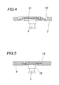
- the kingpin 2 can in different ways with the sliding plate. 3 get connected.
- the kingpin in to use a receiving plate 9, from the top into a stepped passage opening 10 of the sliding plate 3 engages and on the remote opening edge 11 is attached. Due to the necessary for strength reasons Thickness of the sliding plate 3 is the receiving plate 9 in the remote passage opening 10 sunk arranged and therefore does not protrude over the surface the slide plate 3 certain cargo area.
- the kingpin 2 is about its mounting flange 12 screwed from below to the sliding plate 3, for this purpose a recessed recess 13 forms. Also in this embodiment There is no increase in the height, because the mounting flange 12 with the Fixing screws to lie within the recess of the recess 13 comes.
Landscapes
- Engineering & Computer Science (AREA)
- Chemical & Material Sciences (AREA)
- Combustion & Propulsion (AREA)
- Transportation (AREA)
- Mechanical Engineering (AREA)
- Control Of Throttle Valves Provided In The Intake System Or In The Exhaust System (AREA)
- Polysaccharides And Polysaccharide Derivatives (AREA)
- Transition And Organic Metals Composition Catalysts For Addition Polymerization (AREA)
- Vehicle Cleaning, Maintenance, Repair, Refitting, And Outriggers (AREA)
- Auxiliary Methods And Devices For Loading And Unloading (AREA)
- Handcart (AREA)
- Body Structure For Vehicles (AREA)
- Glass Compositions (AREA)
- Permanent Magnet Type Synchronous Machine (AREA)
Abstract
Description
- Fig. 1
- die Aufliegeeinrichtung eines erfindungsgemäßen Sattelanhängers in einer vereinfachten Draufsicht,
- Fig. 2
- einen Schnitt durch die Aufliegeeinrichtung nach der Linie II-II der Fig. 1 in einem größeren Maßstab,
- Fig. 3
- einen Schnitt durch die Aufliegeeinrichtung nach der Linie III-III der Fig. 2,
- Fig. 4
- einen Schnitt durch die Gleitplatte im Bereich des Königszapfens in einem größeren Maßstab und
- Fig. 5
- eine der Fig. 4 entsprechende Darstellung einer Konstruktionsvariante.
Claims (4)
- Sattelanhänger mit einer an Längsträger (4) eines Fahrgestells angebundenen Aufliegeeinrichtung (1), die einen Gestellrahmen (7) mit einer einen Königszapfen (2) tragenden Gleitplatte (3) umfaßt, dadurch gekennzeichnet, daß die Gleitplatte (3) als selbsttragende, an die Längsträger (4) des Fahrgestells angebundene Platte ausgebildet ist und daß der Gestellrahmen (7), der eine höchstens der Dicke der Gleitplatte (3) entsprechende Höhe aufweist, an den längsseitigen Stirnflächen der Gleitplatte (3) anschließt.
- Sattelanhänger nach Anspruch 1, dadurch gekennzeichnet, daß der Gestellrahmen (7) über Formrohre (8) mit einem im wesentlichen rechteckigen Querschnitt an die Gleitplatte (3) angeschlossen ist.
- Sattelanhänger nach Anspruch 1 oder 2, dadurch gekennzeichnet, daß der in einem Aufnahmeteller (9) gehaltene Königszapfen (2) von oben in eine abgesetzte Durchtrittsöffnung (10) der Gleitplatte (3) eingesetzt ist.
- Sattelanhänger nach Anspruch 1 oder 2, dadurch gekennzeichnet, daß der Königszapfen (2) mit seinem Befestigungsflansch (12) in eine Ausnehmung (13) auf der Unterseite der Gleitplatte (3) eingreift.
Priority Applications (1)
| Application Number | Priority Date | Filing Date | Title |
|---|---|---|---|
| SI200530208T SI1600364T1 (sl) | 2004-05-26 | 2005-05-02 | Polprikolica |
Applications Claiming Priority (2)
| Application Number | Priority Date | Filing Date | Title |
|---|---|---|---|
| AT9072004 | 2004-05-26 | ||
| AT0090704A AT413522B (de) | 2004-05-26 | 2004-05-26 | Sattelanhänger |
Publications (3)
| Publication Number | Publication Date |
|---|---|
| EP1600364A2 true EP1600364A2 (de) | 2005-11-30 |
| EP1600364A3 EP1600364A3 (de) | 2006-12-27 |
| EP1600364B1 EP1600364B1 (de) | 2008-01-09 |
Family
ID=34842281
Family Applications (1)
| Application Number | Title | Priority Date | Filing Date |
|---|---|---|---|
| EP05450081A Expired - Lifetime EP1600364B1 (de) | 2004-05-26 | 2005-05-02 | Sattelanhänger |
Country Status (4)
| Country | Link |
|---|---|
| EP (1) | EP1600364B1 (de) |
| AT (2) | AT413522B (de) |
| DE (1) | DE502005002461D1 (de) |
| SI (1) | SI1600364T1 (de) |
Cited By (1)
| Publication number | Priority date | Publication date | Assignee | Title |
|---|---|---|---|---|
| FR2967614A1 (fr) * | 2010-11-18 | 2012-05-25 | Marc Marcel Ellegeest | Attelage automatique totatif a bague |
Family Cites Families (3)
| Publication number | Priority date | Publication date | Assignee | Title |
|---|---|---|---|---|
| FR2657320B1 (fr) * | 1990-01-25 | 1992-09-11 | Europ Semi Remorques | Plateau de remorque ou de semi-remorque muni d'une structure d'attelage de faible epaisseur. |
| DE9110124U1 (de) * | 1991-08-16 | 1991-09-26 | Maschinenfabriken Bernard Krone Gmbh, 4441 Spelle | Sattelanhänger |
| DE20306057U1 (de) * | 2003-03-20 | 2003-07-24 | Cramer Kupplung GmbH & Co. KG, 45356 Essen | Aufliegervorrichtung für einen Sattelanhänger |
-
2004
- 2004-05-26 AT AT0090704A patent/AT413522B/de not_active IP Right Cessation
-
2005
- 2005-05-02 AT AT05450081T patent/ATE383299T1/de active
- 2005-05-02 SI SI200530208T patent/SI1600364T1/sl unknown
- 2005-05-02 EP EP05450081A patent/EP1600364B1/de not_active Expired - Lifetime
- 2005-05-02 DE DE502005002461T patent/DE502005002461D1/de not_active Expired - Lifetime
Non-Patent Citations (1)
| Title |
|---|
| None |
Cited By (1)
| Publication number | Priority date | Publication date | Assignee | Title |
|---|---|---|---|---|
| FR2967614A1 (fr) * | 2010-11-18 | 2012-05-25 | Marc Marcel Ellegeest | Attelage automatique totatif a bague |
Also Published As
| Publication number | Publication date |
|---|---|
| ATA9072004A (de) | 2005-08-15 |
| DE502005002461D1 (de) | 2008-02-21 |
| ATE383299T1 (de) | 2008-01-15 |
| EP1600364A3 (de) | 2006-12-27 |
| SI1600364T1 (sl) | 2008-06-30 |
| EP1600364B1 (de) | 2008-01-09 |
| AT413522B (de) | 2006-03-15 |
Similar Documents
| Publication | Publication Date | Title |
|---|---|---|
| DE69704882T2 (de) | Selbsttragender Kühlwagen | |
| DE602006000206T2 (de) | Bewegbare Wanne für den Transport von einem Sattelauflieger, mit einer solchen Wanne ausgerüsteter Waggon und Ladenverfahren des Sattelaufliegers | |
| DE2933429C2 (de) | In Modulbauweise gefertigter Eisenbahnwagen | |
| WO2012022789A1 (de) | Lageranordnung einer sattelkupplung | |
| AT413522B (de) | Sattelanhänger | |
| DE69408124T2 (de) | Fahrgestell für einen autobus | |
| DE19952997B4 (de) | Befestigungsvorrichtung für eine Sattelkupplung an einem Fahrzeugrahmen | |
| DE9210890U1 (de) | Lastfahrzeug | |
| EP0065623A1 (de) | Flanschkonstruktion für die Schraubverbindung zwischen einem Anhänger-Fahrgestell und dem Rahmen des Anhänger-Aufbaues | |
| EP3348455A1 (de) | Trägerstruktur für ein nicht-angetriebenes nutzfahrzeug | |
| DE3436932C2 (de) | ||
| DE2350565B2 (de) | Schienenfahrzeug, insbesondere gedeckter, grossraeumiger gueterwagen mit verschiebbaren wandteilen | |
| CH630857A5 (en) | Displacement device for the fifth-wheel coupling on a semitrailer motor vehicle | |
| EP0538893B1 (de) | Sattelzugfahrzeug | |
| DE19843396C1 (de) | Bodengruppe für einen Fahrzeuganhänger, vorzugsweise einen Wohnanhänger | |
| EP0982160B1 (de) | Fahrzeugchassis mit Aufprallschutz für Fahrzeuge | |
| DE3523742A1 (de) | Lastzug | |
| EP2754604A1 (de) | Satteldrehplateau | |
| DE19843400A1 (de) | Bodengruppe für einen Fahrzeuganhänger, vorzugsweiseeinen Wohnanhänger | |
| DE1530789A1 (de) | Koenigszapfen fuer die Anhaengerkupplung von Sattelschlepper-Strassenlastzuganhaengern | |
| DE3400878A1 (de) | Lastkraftfahrzeug mit kuppelbarem einachsanhaenger | |
| DE2350565C (de) | Schienenfahrzeug, insbesondere gedeckter, großräumiger Güterwagen mit verschiebbaren Wandteilen | |
| EP1679252A1 (de) | Karosserieverbindungsanordnung | |
| EP0479134B1 (de) | Fahrgestell für Kraftfahrzeuge oder Anhänger | |
| DE29909700U1 (de) | Fahrzeuggespann aus Zugfahrzeug und Aufliegeranhänger |
Legal Events
| Date | Code | Title | Description |
|---|---|---|---|
| PUAI | Public reference made under article 153(3) epc to a published international application that has entered the european phase |
Free format text: ORIGINAL CODE: 0009012 |
|
| AK | Designated contracting states |
Kind code of ref document: A2 Designated state(s): AT BE BG CH CY CZ DE DK EE ES FI FR GB GR HU IE IS IT LI LT LU MC NL PL PT RO SE SI SK TR |
|
| AX | Request for extension of the european patent |
Extension state: AL BA HR LV MK YU |
|
| PUAL | Search report despatched |
Free format text: ORIGINAL CODE: 0009013 |
|
| AK | Designated contracting states |
Kind code of ref document: A3 Designated state(s): AT BE BG CH CY CZ DE DK EE ES FI FR GB GR HU IE IS IT LI LT LU MC NL PL PT RO SE SI SK TR |
|
| AX | Request for extension of the european patent |
Extension state: AL BA HR LV MK YU |
|
| 17P | Request for examination filed |
Effective date: 20070226 |
|
| AKX | Designation fees paid |
Designated state(s): AT BE BG CH CY CZ DE DK EE ES FI FR GB GR HU IE IS IT LI LT LU MC NL PL PT RO SE SI SK TR |
|
| GRAP | Despatch of communication of intention to grant a patent |
Free format text: ORIGINAL CODE: EPIDOSNIGR1 |
|
| GRAS | Grant fee paid |
Free format text: ORIGINAL CODE: EPIDOSNIGR3 |
|
| GRAA | (expected) grant |
Free format text: ORIGINAL CODE: 0009210 |
|
| AK | Designated contracting states |
Kind code of ref document: B1 Designated state(s): AT BE BG CH CY CZ DE DK EE ES FI FR GB GR HU IE IS IT LI LT LU MC NL PL PT RO SE SI SK TR |
|
| REG | Reference to a national code |
Ref country code: GB Ref legal event code: FG4D Free format text: NOT ENGLISH |
|
| REG | Reference to a national code |
Ref country code: CH Ref legal event code: EP |
|
| REG | Reference to a national code |
Ref country code: IE Ref legal event code: FG4D Free format text: LANGUAGE OF EP DOCUMENT: GERMAN |
|
| REF | Corresponds to: |
Ref document number: 502005002461 Country of ref document: DE Date of ref document: 20080221 Kind code of ref document: P |
|
| REG | Reference to a national code |
Ref country code: RO Ref legal event code: EPE |
|
| REG | Reference to a national code |
Ref country code: CH Ref legal event code: PCAR Free format text: PATENTANWALTSBUREAU STEUDTNER;AHORNWEG 12;5702 NIEDERLENZ (CH) Ref country code: CH Ref legal event code: NV Representative=s name: DIPL.-ING. W. STEUDTNER |
|
| PG25 | Lapsed in a contracting state [announced via postgrant information from national office to epo] |
Ref country code: NL Free format text: LAPSE BECAUSE OF FAILURE TO SUBMIT A TRANSLATION OF THE DESCRIPTION OR TO PAY THE FEE WITHIN THE PRESCRIBED TIME-LIMIT Effective date: 20080109 |
|
| NLV1 | Nl: lapsed or annulled due to failure to fulfill the requirements of art. 29p and 29m of the patents act | ||
| PG25 | Lapsed in a contracting state [announced via postgrant information from national office to epo] |
Ref country code: LT Free format text: LAPSE BECAUSE OF FAILURE TO SUBMIT A TRANSLATION OF THE DESCRIPTION OR TO PAY THE FEE WITHIN THE PRESCRIBED TIME-LIMIT Effective date: 20080109 Ref country code: IS Free format text: LAPSE BECAUSE OF FAILURE TO SUBMIT A TRANSLATION OF THE DESCRIPTION OR TO PAY THE FEE WITHIN THE PRESCRIBED TIME-LIMIT Effective date: 20080509 Ref country code: FI Free format text: LAPSE BECAUSE OF FAILURE TO SUBMIT A TRANSLATION OF THE DESCRIPTION OR TO PAY THE FEE WITHIN THE PRESCRIBED TIME-LIMIT Effective date: 20080109 Ref country code: ES Free format text: LAPSE BECAUSE OF FAILURE TO SUBMIT A TRANSLATION OF THE DESCRIPTION OR TO PAY THE FEE WITHIN THE PRESCRIBED TIME-LIMIT Effective date: 20080420 |
|
| GBV | Gb: ep patent (uk) treated as always having been void in accordance with gb section 77(7)/1977 [no translation filed] | ||
| REG | Reference to a national code |
Ref country code: HU Ref legal event code: AG4A Ref document number: E003160 Country of ref document: HU |
|
| PG25 | Lapsed in a contracting state [announced via postgrant information from national office to epo] |
Ref country code: BG Free format text: LAPSE BECAUSE OF FAILURE TO SUBMIT A TRANSLATION OF THE DESCRIPTION OR TO PAY THE FEE WITHIN THE PRESCRIBED TIME-LIMIT Effective date: 20080409 |
|
| ET | Fr: translation filed | ||
| PG25 | Lapsed in a contracting state [announced via postgrant information from national office to epo] |
Ref country code: PL Free format text: LAPSE BECAUSE OF FAILURE TO SUBMIT A TRANSLATION OF THE DESCRIPTION OR TO PAY THE FEE WITHIN THE PRESCRIBED TIME-LIMIT Effective date: 20080109 Ref country code: PT Free format text: LAPSE BECAUSE OF FAILURE TO SUBMIT A TRANSLATION OF THE DESCRIPTION OR TO PAY THE FEE WITHIN THE PRESCRIBED TIME-LIMIT Effective date: 20080609 |
|
| REG | Reference to a national code |
Ref country code: IE Ref legal event code: FD4D |
|
| PG25 | Lapsed in a contracting state [announced via postgrant information from national office to epo] |
Ref country code: IE Free format text: LAPSE BECAUSE OF FAILURE TO SUBMIT A TRANSLATION OF THE DESCRIPTION OR TO PAY THE FEE WITHIN THE PRESCRIBED TIME-LIMIT Effective date: 20080109 Ref country code: DK Free format text: LAPSE BECAUSE OF FAILURE TO SUBMIT A TRANSLATION OF THE DESCRIPTION OR TO PAY THE FEE WITHIN THE PRESCRIBED TIME-LIMIT Effective date: 20080109 Ref country code: SE Free format text: LAPSE BECAUSE OF FAILURE TO SUBMIT A TRANSLATION OF THE DESCRIPTION OR TO PAY THE FEE WITHIN THE PRESCRIBED TIME-LIMIT Effective date: 20080409 |
|
| PLBE | No opposition filed within time limit |
Free format text: ORIGINAL CODE: 0009261 |
|
| STAA | Information on the status of an ep patent application or granted ep patent |
Free format text: STATUS: NO OPPOSITION FILED WITHIN TIME LIMIT |
|
| BERE | Be: lapsed |
Owner name: WILHELM SCHWARZMULLER -G. M.B.H. Effective date: 20080531 |
|
| 26N | No opposition filed |
Effective date: 20081010 |
|
| PG25 | Lapsed in a contracting state [announced via postgrant information from national office to epo] |
Ref country code: MC Free format text: LAPSE BECAUSE OF NON-PAYMENT OF DUE FEES Effective date: 20080531 Ref country code: GB Free format text: LAPSE BECAUSE OF FAILURE TO SUBMIT A TRANSLATION OF THE DESCRIPTION OR TO PAY THE FEE WITHIN THE PRESCRIBED TIME-LIMIT Effective date: 20080109 |
|
| PG25 | Lapsed in a contracting state [announced via postgrant information from national office to epo] |
Ref country code: EE Free format text: LAPSE BECAUSE OF FAILURE TO SUBMIT A TRANSLATION OF THE DESCRIPTION OR TO PAY THE FEE WITHIN THE PRESCRIBED TIME-LIMIT Effective date: 20080109 |
|
| PG25 | Lapsed in a contracting state [announced via postgrant information from national office to epo] |
Ref country code: BE Free format text: LAPSE BECAUSE OF NON-PAYMENT OF DUE FEES Effective date: 20080531 |
|
| PG25 | Lapsed in a contracting state [announced via postgrant information from national office to epo] |
Ref country code: CY Free format text: LAPSE BECAUSE OF FAILURE TO SUBMIT A TRANSLATION OF THE DESCRIPTION OR TO PAY THE FEE WITHIN THE PRESCRIBED TIME-LIMIT Effective date: 20080109 |
|
| PG25 | Lapsed in a contracting state [announced via postgrant information from national office to epo] |
Ref country code: LU Free format text: LAPSE BECAUSE OF NON-PAYMENT OF DUE FEES Effective date: 20080502 |
|
| PGFP | Annual fee paid to national office [announced via postgrant information from national office to epo] |
Ref country code: FR Payment date: 20100609 Year of fee payment: 6 Ref country code: HU Payment date: 20100409 Year of fee payment: 6 Ref country code: RO Payment date: 20100426 Year of fee payment: 6 |
|
| PG25 | Lapsed in a contracting state [announced via postgrant information from national office to epo] |
Ref country code: TR Free format text: LAPSE BECAUSE OF FAILURE TO SUBMIT A TRANSLATION OF THE DESCRIPTION OR TO PAY THE FEE WITHIN THE PRESCRIBED TIME-LIMIT Effective date: 20080109 |
|
| PGFP | Annual fee paid to national office [announced via postgrant information from national office to epo] |
Ref country code: CZ Payment date: 20100310 Year of fee payment: 6 Ref country code: IT Payment date: 20100527 Year of fee payment: 6 Ref country code: SI Payment date: 20100407 Year of fee payment: 6 Ref country code: SK Payment date: 20100423 Year of fee payment: 6 |
|
| PG25 | Lapsed in a contracting state [announced via postgrant information from national office to epo] |
Ref country code: GR Free format text: LAPSE BECAUSE OF FAILURE TO SUBMIT A TRANSLATION OF THE DESCRIPTION OR TO PAY THE FEE WITHIN THE PRESCRIBED TIME-LIMIT Effective date: 20080410 |
|
| PGFP | Annual fee paid to national office [announced via postgrant information from national office to epo] |
Ref country code: CH Payment date: 20100604 Year of fee payment: 6 |
|
| REG | Reference to a national code |
Ref country code: CH Ref legal event code: PCAR Free format text: PATENTANWALTSBUERO STEUDTNER;AHORNWEG 6;5702 NIEDERLENZ (CH) |
|
| REG | Reference to a national code |
Ref country code: CH Ref legal event code: PL |
|
| PG25 | Lapsed in a contracting state [announced via postgrant information from national office to epo] |
Ref country code: CZ Free format text: LAPSE BECAUSE OF NON-PAYMENT OF DUE FEES Effective date: 20110502 Ref country code: HU Free format text: LAPSE BECAUSE OF NON-PAYMENT OF DUE FEES Effective date: 20110503 Ref country code: LI Free format text: LAPSE BECAUSE OF NON-PAYMENT OF DUE FEES Effective date: 20110531 Ref country code: CH Free format text: LAPSE BECAUSE OF NON-PAYMENT OF DUE FEES Effective date: 20110531 |
|
| REG | Reference to a national code |
Ref country code: SI Ref legal event code: KO00 Effective date: 20111206 |
|
| REG | Reference to a national code |
Ref country code: SK Ref legal event code: MM4A Ref document number: E 3394 Country of ref document: SK Effective date: 20110502 |
|
| REG | Reference to a national code |
Ref country code: FR Ref legal event code: ST Effective date: 20120131 |
|
| PG25 | Lapsed in a contracting state [announced via postgrant information from national office to epo] |
Ref country code: IT Free format text: LAPSE BECAUSE OF NON-PAYMENT OF DUE FEES Effective date: 20110502 Ref country code: SI Free format text: LAPSE BECAUSE OF NON-PAYMENT OF DUE FEES Effective date: 20110503 Ref country code: SK Free format text: LAPSE BECAUSE OF NON-PAYMENT OF DUE FEES Effective date: 20110502 |
|
| PG25 | Lapsed in a contracting state [announced via postgrant information from national office to epo] |
Ref country code: FR Free format text: LAPSE BECAUSE OF NON-PAYMENT OF DUE FEES Effective date: 20110531 |
|
| PG25 | Lapsed in a contracting state [announced via postgrant information from national office to epo] |
Ref country code: RO Free format text: LAPSE BECAUSE OF NON-PAYMENT OF DUE FEES Effective date: 20110502 |
|
| PGFP | Annual fee paid to national office [announced via postgrant information from national office to epo] |
Ref country code: AT Payment date: 20120504 Year of fee payment: 8 |
|
| PGFP | Annual fee paid to national office [announced via postgrant information from national office to epo] |
Ref country code: DE Payment date: 20130411 Year of fee payment: 9 |
|
| REG | Reference to a national code |
Ref country code: DE Ref legal event code: R119 Ref document number: 502005002461 Country of ref document: DE |
|
| REG | Reference to a national code |
Ref country code: AT Ref legal event code: MM01 Ref document number: 383299 Country of ref document: AT Kind code of ref document: T Effective date: 20140502 |
|
| REG | Reference to a national code |
Ref country code: DE Ref legal event code: R119 Ref document number: 502005002461 Country of ref document: DE Effective date: 20141202 |
|
| PG25 | Lapsed in a contracting state [announced via postgrant information from national office to epo] |
Ref country code: AT Free format text: LAPSE BECAUSE OF NON-PAYMENT OF DUE FEES Effective date: 20140502 |
|
| PG25 | Lapsed in a contracting state [announced via postgrant information from national office to epo] |
Ref country code: DE Free format text: LAPSE BECAUSE OF NON-PAYMENT OF DUE FEES Effective date: 20141202 |