EP1600640A2 - Lüfterhaube für einen Wärmeübertrager, insbesondere für Kraftfahrzeuge - Google Patents
Lüfterhaube für einen Wärmeübertrager, insbesondere für Kraftfahrzeuge Download PDFInfo
- Publication number
- EP1600640A2 EP1600640A2 EP05008981A EP05008981A EP1600640A2 EP 1600640 A2 EP1600640 A2 EP 1600640A2 EP 05008981 A EP05008981 A EP 05008981A EP 05008981 A EP05008981 A EP 05008981A EP 1600640 A2 EP1600640 A2 EP 1600640A2
- Authority
- EP
- European Patent Office
- Prior art keywords
- fan
- struts
- fan cover
- cover according
- curved
- Prior art date
- Legal status (The legal status is an assumption and is not a legal conclusion. Google has not performed a legal analysis and makes no representation as to the accuracy of the status listed.)
- Withdrawn
Links
Images

Classifications
-
- F—MECHANICAL ENGINEERING; LIGHTING; HEATING; WEAPONS; BLASTING
- F01—MACHINES OR ENGINES IN GENERAL; ENGINE PLANTS IN GENERAL; STEAM ENGINES
- F01P—COOLING OF MACHINES OR ENGINES IN GENERAL; COOLING OF INTERNAL-COMBUSTION ENGINES
- F01P5/00—Pumping cooling-air or liquid coolants
- F01P5/02—Pumping cooling-air; Arrangements of cooling-air pumps, e.g. fans or blowers
- F01P5/06—Guiding or ducting air to, or from, ducted fans
-
- F—MECHANICAL ENGINEERING; LIGHTING; HEATING; WEAPONS; BLASTING
- F01—MACHINES OR ENGINES IN GENERAL; ENGINE PLANTS IN GENERAL; STEAM ENGINES
- F01P—COOLING OF MACHINES OR ENGINES IN GENERAL; COOLING OF INTERNAL-COMBUSTION ENGINES
- F01P11/00—Component parts, details, or accessories not provided for in, or of interest apart from, groups F01P1/00 - F01P9/00
- F01P11/12—Filtering, cooling, or silencing cooling-air
-
- F—MECHANICAL ENGINEERING; LIGHTING; HEATING; WEAPONS; BLASTING
- F04—POSITIVE - DISPLACEMENT MACHINES FOR LIQUIDS; PUMPS FOR LIQUIDS OR ELASTIC FLUIDS
- F04D—NON-POSITIVE-DISPLACEMENT PUMPS
- F04D29/00—Details, component parts, or accessories
- F04D29/40—Casings; Connections of working fluid
- F04D29/52—Casings; Connections of working fluid for axial pumps
- F04D29/54—Fluid-guiding means, e.g. diffusers
- F04D29/541—Specially adapted for elastic fluid pumps
- F04D29/542—Bladed diffusers
- F04D29/544—Blade shapes
-
- F—MECHANICAL ENGINEERING; LIGHTING; HEATING; WEAPONS; BLASTING
- F04—POSITIVE - DISPLACEMENT MACHINES FOR LIQUIDS; PUMPS FOR LIQUIDS OR ELASTIC FLUIDS
- F04D—NON-POSITIVE-DISPLACEMENT PUMPS
- F04D29/00—Details, component parts, or accessories
- F04D29/66—Combating cavitation, whirls, noise, vibration or the like; Balancing
- F04D29/661—Combating cavitation, whirls, noise, vibration or the like; Balancing especially adapted for elastic fluid pumps
- F04D29/663—Sound attenuation
Definitions
- the invention relates to a fan cover for a permeable by air Heat exchanger according to the preamble of claim 1.
- Fan cowlings are used for ducting fan units with fan blower the air flow and used to hold the fan blower.
- a Heat exchanger z. B. a coolant radiator fan cover arranged, which is attached to the heat exchanger and a circular Frame, within which a driven by an electric motor Axial fan to promote the flow of air through the heat exchanger rotates.
- the electric motor with the fan called fan blower for short, is over individual struts connected to the frame or the fan cover, where it In many cases, one-piece, molded plastic components are involved.
- Such a fan orderaggrogat for a motor vehicle has been known from DE-A 42 44 037 of the Applicant
- the fan guard by means of locking connections on the radiator and the fan blower on one Attached fastening ring, which radially and substantially in one Level arranged struts is held.
- the struts Forces and moments which consist of the weight and the mass forces of the Blower with electric motor, the reaction torque and the axial thrust of the Fans result, are not insignificant, so the struts accordingly must be strongly dimensioned. Especially in the axial direction must be given sufficient rigidity, hence the fan or the motor does not hit or rub against the heat exchanger.
- the Struts occupy only a minimal portion of the frame cross-section to the flow losses for the air flow conveyed by the fan are so small as possible to have. Therefore, the struts are as slim as possible streamlined, partially formed with a flow profile.
- Fan noise is due to the air flow due to standing Struts and rotating fan blades result.
- a fan guard of the beginning type with respect to their axial rigidity to improve, namely possibly without the weight, the number and / or the cross sections of the struts to increase.
- the struts are curved in such a way that they each span a curved surface with their inflow and outflow edges, which preferably the surface of a spheroid or a Dome forms.
- an envelope for example the surface of the spheroid (paraboloid, ellipsoid) by rotation a Kurvenastes generated around the axis of rotation of the fan.
- Curve branch can be part of a circle, a parabola, an ellipse or a other non-linear curve whose distance in the axial direction to a Radial plane in the radial direction from the inside out constantly growing. This achieves a similar supporting effect for the struts, as he did in Domes or vaults is known, and in particular in the radially outer Area where the mechanical stress is strongest.
- the struts on the one hand between heat exchanger and fan ie in the flow direction before Be fan and arranged in the flow direction behind the fan.
- the distance between the leading edges the fan and the trailing edges of the struts or the distance between the trailing edges of the fan and the leading edges of the struts growing radially from the inside out brings advantages in the field of aerodynamics and the noise, because in the outer diameter range the largest flow rates occur and the largest flow rates be achieved while at the same time the distance between fans and striving is greatest. This will be the harmful interference significantly reduced.
- the object of the invention is also achieved by the features of the claim 10 solved.
- the differently inclined struts can be different dimensioned, d. H. be designed as compression and tension struts, wherein the compression struts are dimensioned stronger than the tie rods.
- d. H. be designed as compression and tension struts, wherein the compression struts are dimensioned stronger than the tie rods.
- a gain the cross-section of the struts in particular in the outer diameter range where the largest bending stress due axial load occurs.
- the strut cross sections thus take along increasing radius, either the strut height (in the air flow direction) or the strut width (transverse to the direction of air flow) increased can be.
- the crossing points are in Arranged areas with substantially axial flow. Because in these areas a radial component of the flow is minimal, The crossing points in such an arrangement are lower Flow resistance.
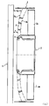
- Fig. 1 shows an arrangement of a heat exchanger 1, a fan cover 2 and a fan blower 3, which is attached via a number of struts 4 relative to the fan cover 2.
- the heat exchanger 1 may preferably be formed as a coolant / air cooler of a motor vehicle and arranged in a front engine compartment of a motor vehicle, not shown.
- the fan cover 2 is also shown only incomplete, it is in a manner not shown, but known from the prior art with the radiator 1, z. B. connected via a latching connection.
- the fan cowl 2 has at its downstream end a frame 2a, in which an axial fan 3a rotates, which is driven by an electric motor 3b.
- the common axis of rotation is designated 3c.
- the blower 3 consisting of electric motor 3b and fan 3a has a retaining ring 5 on which the struts 4 are fastened and thus hold the blower 3 inside the fan cowl 2;
- the blower 3 is fixed both in the radial direction relative to the fan frame 2 a and in the axial direction relative to the network of the radiator 1.
- the struts 4 have in cross section a flow-favorable profile 4a, which is characterized by a strut height h in the air flow direction and a maximum strut width b transversely to the air flow direction.
- the strut profile may have different cross-sections, ie different heights and / or widths in the radial direction - therefore another strut profile 4b is shown with a smaller cross-section struts 4 each have leading or trailing edges 6 and trailing or trailing edges 7 shown in dashed lines.
- Both the leading edges 6 and the trailing edges 7 are - in this embodiment - contrary to the direction of air flow, ie curved in the direction of the radiator 1 - they each span a strut 4 enveloping surface, which forms part of the surface of a spheroid. ie forms a body of revolution.
- a spheroid is produced by rotation of a curved branch (a so-called generator) about an axis of rotation;
- the generatrices are the leading edges 6 and the trailing edges 7 of the struts 4, ie both are in the plane of the drawing. They each have a non-linear curve, ie, the leading edge 6 and the trailing edge 7 z.
- a variable spacing is x between the rear edge 7 of the strut 4 and the entrance plane E of the axial fan 3a, it ie resulting radially inward a minimum distance x i and radially outwardly a maximum distance x a -, the distance x thus non-linear (progressive) with increasing radius (distance from the axis of rotation 3c) too.
- the struts 4 obtained by the described curvature increased structural strength, ie by the curved formation, in which the struts 4 quasi form the framework of a dome, there is a support effect, in particular under axial load in the direction of the axis of rotation 3c.
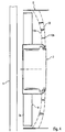
- Fig. 2 shows a second embodiment of the invention, wherein the same reference numerals are used for the same parts, ie for the heat exchanger 1 and the fan 3 and the fan cover 2.
- the fan 3 is fixed by means of the retaining ring 5 via struts 8 against the fan cover 2, wherein the struts 8 have leading edges 8a and trailing edges 8b, which are here curved in the direction of the air flow, corresponding to the arrow L.
- the axial distance x i in the radially inner region between the network of the heat exchanger 1 and the front edge 8 a is smaller than the distance x a in the radially outer region.
- the support struts 8 are therefore the same here as in the embodiment of FIG. 1.
- the fan cover 2 is preferably attached to the heat exchanger 1, ie the From the fan 3 outgoing, transmitted via the struts 8 forces are absorbed by the heat exchanger 1 and its storage in the vehicle.
- a support of the fan cover 2 in other ways, eg. B. directly opposite the vehicle is also possible.
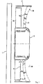
- Fig. 3 shows a further (third) embodiment of the invention, in which the fan 3 is held by struts 9 with respect to the fan cowl 2 and the struts 9 are arranged downstream of the fan 3a.
- the struts 9 have a front edge 9a and a rear edge 9b, which are curved in the direction of the air flow.
- the distance x between an exit plane A of the axial fan 3a and the front edge 9a of the struts 9 thus increases with increasing radius, ie the outer distance x a is greater than the inner distance x i , where x increases progressively from x i to x a .
- aerodynamic advantages in particular in the radially outer region, are associated with a reduction in noise and an increase in efficiency.
- Fig. 4 shows a further (fourth) embodiment of the invention, in which the fan 3 is supported by struts 10 relative to the fan cover 2.
- the struts 10 have leading edges 10a and trailing edges 10b, which are curved against the air flow direction and arranged behind the exit plane A of the axial fan 3a.
- This embodiment thus represents a reflection of the embodiment according to FIG. 3.
- the supporting effect according to the invention due to the dome-shaped curvature of the struts 10 is also given here.
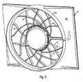
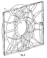
- Fig. 5 shows another (fifth) embodiment of the invention, namely a fan cover 11 with a fan frame 11 a, within which an electric motor 12 is arranged for driving a fan wheel, not shown.
- the fan cover 11 is shown with its back 11 b and connected in a manner not shown on its front with a heat exchanger, also not shown.
- the electric motor 12 is received in a retaining ring 13, which is connected via a strut grid 14 with the fan cover 11.
- the strut grid 14 consists of struts 15, which are curved in the clockwise direction in the circumferential direction, and of struts 16, which are curved in the opposite circumferential direction.
- the struts 15, 16 are arranged such that a plurality of crossing points 17 results between them, which form the lattice structure 14 together with the struts 15, 16.
- a part of the struts can be formed as compression struts 15 and another part of the struts as tension struts 16, whereby also the radial rigidity is increased.
- the tie rods can be slimmer, ie formed with a smaller cross-section.
- the fan cover 11 including frame 11 a, strut grid 14 and retaining ring 13 can be made as a one-piece plastic injection molded part.
- the strut grid 14, consisting of circumferentially curved struts 15, 16 can be arranged both in a plane and on the surface of a spheroid - as described in the previous embodiments. Due to the additional dome-shaped curvature of the strut grid 14 so an additional axial rigidity can be achieved by increasing the structural strength.
- Fig. 6 shows the fan cover 11 of FIG. 5 in a view in the air flow direction with struts 15, 16, which form the strut grid 14 for holding the retaining ring 13 - the blower is not shown here.
- Suction fan d. H. an arrangement of fan shroud and fan blower in the air flow direction behind the heat exchanger.
- a fan cowl assembly with oppressive fan d. H. in the direction of air flow in front of the heat exchanger.
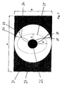
- FIG. 7 shows a fan cowl 21 in a schematic view in the air flow direction with only indicated struts 22, 23, 28, 29, which intersect at a crossing point 24.
- the respective shape of the strut pairs 22, 23 and 28, 29 is to be adapted to the respective stability requirements.
- crossing points are arranged along an ellipse 25 with half-axes c and d. In the area of the ellipse 25, the flow is predominantly axial, that is to say perpendicular to the plane of FIG. 7. Since the points of intersection represent an increased flow resistance with a component within the plane of FIG. 7, a total flow resistance of the fan cover 21 is in this arrangement reduced.
- CFD flow simulations of a rectangular fan cowl without struts also lead to an elliptical shape.
- the flow is within the Ellipse 25 due to a deflection by the Luftlassabe 26 obliquely directed outside, so has a radial component to the outside.
- the ellipse is the flow through a distraction through the outer surface 27 of the fan cover 21 directed obliquely inward, so has a radial component inward.
- the elliptical shape results from the elongated rectangular shape of the fan guard 21.
- rectangular Fan cowls with the edge lengths a and b as shown in FIG. 7 and more circular Fan opening an ellipse with the semiaxes c and d, where b is smaller as a is and c is less than d.
- the elongated shape of the ellipse is thus opposite the elongated shape of the fan cover rotated 90 °.
Landscapes
- Engineering & Computer Science (AREA)
- Mechanical Engineering (AREA)
- General Engineering & Computer Science (AREA)
- Chemical & Material Sciences (AREA)
- Combustion & Propulsion (AREA)
- Physics & Mathematics (AREA)
- Geometry (AREA)
- Structures Of Non-Positive Displacement Pumps (AREA)
Abstract
Description
- Fig. 1
- ein erstes Ausführungsbeispiel der Erfindung mit entgegen der Luftströmungsrichtung gekrümmten Streben zwischen Wärmeübertrager und Lüfter,
- Fig. 2
- ein zweites Ausführungsbeispiel der Erfindung mit in LuftströmungsRichtung gekrümmten Streben zwischen Wärmeübertrager und Lüfter,
- Fig. 3
- ein drittes Ausführungsbeispiel der Erfindung mit in LuftströmungsRichtung gekrümmten Streben stromabwärts vom Lüfter,
- Fig. 4
- ein viertes Ausführungsbeispiel der Erfindung mit entgegen der Luftströmungsrichtung gekrümmten Streben stromabwärts vom Lüfter.
- Fig. 5
- ein fünftes Ausführungsbeispiel der Erfindung mit einem Strebengitter in einer Ansicht entgegen der Luftsirömungsrichtung,
- Fig. 6
- das Ausführungsbeispiel gemäß Fig. 5 in einer Ansicht in Luftströmungsrichtung auf die Lüfterhaube mit Strebengitter und
- Fig. 7
- eine schematische Ansicht einer Lüfterhaube mit gekreuzten Streben.
Claims (15)
- Lüfterhaube (2) für einen von Luft durchströmbaren Wärmeübertrager (1) mit einem aus einem Axiallüfter (3a) und einem Antriebsmotor (3b) bestehenden Lüftergebläse (3), welches über Streben mit der Lüfterhaube (2) verbunden ist, wobei die Streben ein Querschnittsprofil mit einer Vorder- und einer Hinterkante sowie einer Strebenhöhe h und einer Strebenbreite b aufweisen, dadurch gekennzeichnet, dass die Streben (4, 8, 9, 10), insbesondere ihre Vorder- und/oder ihre Hinterkanten (6, 7; 8a, 8b; 9a, 9b; 10a, 10b) in einer nichtebenen, insbesondere sphärischen oder sphäroiden Fläche angeordnet sind.
- Lüfterhaube nach Anspruch 1, dadurch gekennzeichnet, dass die umhüllende Fläche durch einen um die Rotationsachse (3c) des Gebläses (3) rotierenden, nicht linearen Kurvenast (6, 7; 8a, 8b) erzeugbar ist, welcher einen mit zunehmendem Abstand von der Rotationsachse (3c) zunehmenden Abstand x von einer Radialebene (E, A) aufweist.
- Lüfterhaube nach Anspruch 2, dadurch gekennzeichnet, dass der Kurvenast (6, 7; 10a, 10b) entgegen der Luftströmungsrichtung L gekrümmt ist.
- Lüfterhaube nach Anspruch 2, dadurch gekennzeichnet, dass der Kurvenast (8a, 8b; 9a, 9b) in Luftstromungsnchtung L gekrümmt ist.
- Lüfterhaube nach Anspruch 3 oder 4, dadurch gekennzeichnet, dass die Streben (9, 10) in Luftströmungsrichtung hinter dem Lüfter (3a) angeordnet sind.
- Lüfterhaube nach Anspruch 3 oder 4, dadurch gekennzeichnet, dass die Streben (4, 8) in Luftströmungsrichtung vor dem Lüfter (3a) angeordnet sind.
- Lüfterhaube nach einem der vorhergehenden Ansprüche, dadurch gekennzeichnet, dass der Strebenquerschnitt (4a, 4b) mit zunehmendem Abstand von der Rotationsachse (3c) zunimmt.
- Lüfterhaube nach Anspruch 7, dadurch gekennzeichnet, dass die Strebenhöhe h mit zunehmendem Abstand zunimmt.
- Lüfterhaube nach Anspruch 7 oder 8, dadurch gekennzeichnet, dass die Strebenbreite b mit zunehmendem Abstand zunimmt.
- Lüfterhaube (11) für einen von Luft durchströmbaren Wärmeübertrager mit einem aus einem Axiallüfter und einem Antriebsmotor (12) bestehenden Lüftergebläse, welches über Streben mit der Lüfterhaube (11) verbunden ist, dadurch gekennzeichnet, dass die Streben (15, 16) in Umfangsrichtung gegensinnig geneigt bzw. gekrümmt angeordnet sind und ein Strebengitter (14) mit Kreuzungspunkten (17) bilden.
- Lüfterhaube nach einem der Ansprüche 1 bis 9, dadurch gekennzeichnet, dass die Streben (15, 16) in Umfangsrichtung gegensinnig geneigt bzw. gekrümmt angeordnet sind und ein Strebengitter (14) mit Kreuzungspunkten (17) bilden.
- Lüfterhaube nach Anspruch 10 oder 11, dadurch gekennzeichnet, dass die Streben in einer Umfangsrichtung als Druckstreben (15) und in der anderen Umfangsrichtung als Zugstreben (16) ausgebildet sind, wobei die Druckstreben einen größeren Querschnitt als die Zugstreben aufweisen.
- Lüfterhaube nach einem der Ansprüche 10 bis 12, dadurch gekennzeichnet, dass die Kreuzungspunkte in Bereichen mit im wesentlichen axialer Durchströmung angeordnet sind.
- Lüfterhaube nach einem der Ansprüche 10 bis 13, dadurch gekennzeichnet, dass die Kreuzungspunkte auf einer Ellipse angeordnet sind.
- Lüfterhaube nach Anspruch 14, dadurch gekennzeichnet, dass ein Längenverhältnis der Hauptachsen der Ellipse dem Kehrwert eines Längenverhäknisses der dazu jeweils parallelen Seitenkanten der Lüfterhaube entspricht.
Applications Claiming Priority (2)
| Application Number | Priority Date | Filing Date | Title |
|---|---|---|---|
| DE102004020508 | 2004-04-26 | ||
| DE102004020508 | 2004-04-26 |
Publications (2)
| Publication Number | Publication Date |
|---|---|
| EP1600640A2 true EP1600640A2 (de) | 2005-11-30 |
| EP1600640A3 EP1600640A3 (de) | 2009-11-04 |
Family
ID=34935660
Family Applications (1)
| Application Number | Title | Priority Date | Filing Date |
|---|---|---|---|
| EP05008981A Withdrawn EP1600640A3 (de) | 2004-04-26 | 2005-04-25 | Lüfterhaube für einen Wärmeübertrager, insbesondere für Kraftfahrzeuge |
Country Status (2)
| Country | Link |
|---|---|
| US (1) | US7811055B2 (de) |
| EP (1) | EP1600640A3 (de) |
Cited By (7)
| Publication number | Priority date | Publication date | Assignee | Title |
|---|---|---|---|---|
| EP1998052A3 (de) * | 2007-06-01 | 2009-10-28 | EVG Lufttechnik GmbH | Axiallüfter mit nachgeschaltetem Leitapparat |
| EP1887195A3 (de) * | 2006-08-10 | 2012-04-18 | Behr GmbH & Co. KG | Kühlvorrichtung für ein Kraftfahrzeug |
| WO2013156257A1 (fr) * | 2012-04-19 | 2013-10-24 | Valeo Systemes Thermiques | Ventilateur pour automobile comportant un stator en amont de l'helice |
| EP2886384A1 (de) * | 2013-12-20 | 2015-06-24 | Valeo Systemes Thermiques | Gebläse für ein mit einem Stator ausgestattetes Kraftfahrzeug |
| CN106687753A (zh) * | 2015-03-27 | 2017-05-17 | 三菱电机株式会社 | 空气调节机的室内机 |
| WO2025195652A1 (de) * | 2024-03-20 | 2025-09-25 | Truma Gerätetechnik GmbH & Co. KG | Lufteinlassgitter für eine lufteinlassöffnung eines heizgeräts |
| EP4686832A1 (de) * | 2024-07-31 | 2026-02-04 | Viessmann Holding International GmbH | Motorträger für einen ventilator |
Families Citing this family (28)
| Publication number | Priority date | Publication date | Assignee | Title |
|---|---|---|---|---|
| US20080078340A1 (en) * | 2006-09-28 | 2008-04-03 | Siemens Vdo Automotive Canada Inc. | Fan Module motor mont arms with shape optimization |
| KR20080062891A (ko) * | 2006-12-29 | 2008-07-03 | 엘지전자 주식회사 | 공기조화기의 팬 |
| ITBO20070776A1 (it) * | 2007-11-23 | 2009-05-24 | Spal Automotive Srl | Unita' di ventilazione in particolare per autoveicoli. |
| US20130189129A1 (en) * | 2012-01-23 | 2013-07-25 | Lasko Holdings, Inc. | Low Noise Air Movement Generator |
| WO2014006649A1 (ja) * | 2012-07-03 | 2014-01-09 | 三菱電機株式会社 | 空気調和機の室内機、及びこの室内機を備えた空気調和機 |
| DE102012109542A1 (de) * | 2012-10-08 | 2014-04-10 | Ebm-Papst Mulfingen Gmbh & Co. Kg | "Strömungsgleichrichter für einen Axiallüfter" |
| DE102012222259A1 (de) * | 2012-12-04 | 2014-06-05 | Magna Electronics Europe Gmbh & Co.Kg | Lüfteranordnung |
| CN104937346B (zh) | 2013-01-11 | 2018-07-27 | 开利公司 | 具有罩风扇的风扇盘管单元 |
| US10253676B2 (en) | 2013-12-20 | 2019-04-09 | Magna Powertrain Bad Homburg GmbH | Molded rotor for cooling fan motor |
| WO2015138672A1 (en) * | 2014-03-13 | 2015-09-17 | Magna Electronics Inc. | Vehicle cooling fan with aerodynamic stator struts |
| CN107923413B (zh) * | 2015-08-10 | 2020-12-01 | 三菱电机株式会社 | 送风机以及空气调节装置 |
| KR102489427B1 (ko) * | 2016-05-31 | 2023-01-18 | 삼성전자주식회사 | 팬 가드 조립체 및 이를 구비하는 실외기 |
| DE102016221642A1 (de) * | 2016-11-04 | 2018-05-09 | Brose Fahrzeugteile GmbH & Co. Kommanditgesellschaft, Würzburg | Zargenvorrichtung für ein Kühlerlüftermodul, ein Kühlerlüftermodul mit einer Zargenvorrichtung und Fahrzeug mit einem solchen Kühlerlüftermodul |
| WO2018131183A1 (ja) * | 2017-01-10 | 2018-07-19 | 三菱電機株式会社 | 送風機及び空気調和装置 |
| DE102017126823A1 (de) * | 2017-11-15 | 2019-05-16 | Brose Fahrzeugteile GmbH & Co. Kommanditgesellschaft, Würzburg | Kühlerlüftermodul |
| FR3081383B1 (fr) * | 2018-05-22 | 2023-10-20 | Valeo Systemes Thermiques | Dispositif de ventilation d’un vehicule automobile |
| JP2020002888A (ja) * | 2018-06-29 | 2020-01-09 | パナソニックIpマネジメント株式会社 | 扇風機 |
| DE102018128792A1 (de) * | 2018-11-16 | 2020-05-20 | Ebm-Papst Mulfingen Gmbh & Co. Kg | Kompakter Diagonalventilator mit Nachleiteinrichtung |
| USD938011S1 (en) | 2019-12-10 | 2021-12-07 | Regal Beloit America, Inc. | Fan blade |
| US11555508B2 (en) | 2019-12-10 | 2023-01-17 | Regal Beloit America, Inc. | Fan shroud for an electric motor assembly |
| USD938009S1 (en) | 2019-12-10 | 2021-12-07 | Regal Beloit America, Inc. | Fan hub |
| US11371517B2 (en) | 2019-12-10 | 2022-06-28 | Regal Beloit America, Inc. | Hub inlet surface for an electric motor assembly |
| USD938010S1 (en) | 2019-12-10 | 2021-12-07 | Regal Beloit America, Inc. | Fan hub |
| US11859634B2 (en) | 2019-12-10 | 2024-01-02 | Regal Beloit America, Inc. | Fan hub configuration for an electric motor assembly |
| USD952830S1 (en) | 2019-12-10 | 2022-05-24 | Regal Beloit America, Inc. | Fan shroud |
| FR3108147B1 (fr) * | 2020-03-13 | 2022-02-25 | Valeo Systemes Thermiques | Bras de maintien pour armature de support |
| US11927202B2 (en) * | 2020-04-21 | 2024-03-12 | Quanta Computer Inc. | Server fan guard |
| WO2022040309A1 (en) | 2020-08-18 | 2022-02-24 | Breezer Holdings, Llc | Rotating plate misting fan |
Family Cites Families (24)
| Publication number | Priority date | Publication date | Assignee | Title |
|---|---|---|---|---|
| DE607134C (de) | 1932-10-26 | 1934-12-18 | Paul Havard | Leitschaufeln fuer Schraubenventilatoren |
| US2142307A (en) * | 1934-06-14 | 1939-01-03 | Mey Rene De | Mounting of axial flow fans and the like |
| US2224519A (en) * | 1938-03-05 | 1940-12-10 | Macard Screws Ltd | Screw type fluid propelling apparatus |
| US2557223A (en) * | 1948-06-17 | 1951-06-19 | Edmund E Hans | Means for supporting a fan in a housing opening |
| GB733544A (en) | 1952-11-10 | 1955-07-13 | Henning Guenther Bartels | Device for increasing pressure or speed of a fluid flowing in a pipeline |
| FR1254416A (fr) | 1959-10-16 | 1961-02-24 | Bertin & Cie | Diffuseur pour fluide et appareils en comportant application |
| FR1360211A (fr) | 1963-03-04 | 1964-05-08 | A De Jong N V | Ventilateur axial |
| US3883264A (en) * | 1971-04-08 | 1975-05-13 | Gadicherla V R Rao | Quiet fan with non-radial elements |
| JPS5524399Y2 (de) | 1974-09-10 | 1980-06-11 | ||
| US4685513A (en) * | 1981-11-24 | 1987-08-11 | General Motors Corporation | Engine cooling fan and fan shrouding arrangement |
| US5246339A (en) | 1988-06-08 | 1993-09-21 | Abb Flakt Ab | Guide vane for an axial fan |
| JPH0692723B2 (ja) * | 1990-03-19 | 1994-11-16 | 株式会社日立製作所 | 軸流流体機械 |
| DE9017417U1 (de) | 1990-12-22 | 1991-03-14 | Behr GmbH & Co, 7000 Stuttgart | Lüfteraggregat für einen Kühler |
| DE4105378A1 (de) | 1991-02-21 | 1992-08-27 | Bosch Gmbh Robert | Axialluefter |
| US5342167A (en) * | 1992-10-09 | 1994-08-30 | Airflow Research And Manufacturing Corporation | Low noise fan |
| DE4244037C2 (de) | 1992-12-24 | 1995-10-05 | Behr Gmbh & Co | Kühlaggregat für einen Verbrennungsmotor |
| JP3409496B2 (ja) * | 1995-03-30 | 2003-05-26 | 日産自動車株式会社 | ラジエータ構造 |
| US6139265A (en) * | 1996-05-01 | 2000-10-31 | Valeo Thermique Moteur | Stator fan |
| DE19638518A1 (de) | 1996-09-20 | 1998-04-02 | Distelkamp Stroemungstechnik | Axiallüfter, insbesondere zur Luftförderung durch den Wärmetauscher eines Kraftfahrzeuges |
| KR100548036B1 (ko) * | 1998-12-31 | 2006-05-09 | 한라공조주식회사 | 축류팬용 안내깃과 그 안내깃을 구비한 축류팬 슈라우드 조립체 |
| EP1290349B1 (de) * | 2000-06-16 | 2006-08-16 | Robert Bosch Corporation | Kühlventilator mit trichterförmigem mantel und entsprechender blattform |
| US20040012125A1 (en) | 2001-06-19 | 2004-01-22 | Plant William D. | Blow molded fan shroud |
| US6772606B2 (en) | 2002-07-15 | 2004-08-10 | Maytag Corporation | Method and apparatus for a plastic evaporator fan shroud assembly |
| KR100937929B1 (ko) * | 2003-07-01 | 2010-01-21 | 한라공조주식회사 | 축류팬 쉬라우드의 스테이터 |
-
2005
- 2005-04-25 US US11/113,321 patent/US7811055B2/en not_active Expired - Fee Related
- 2005-04-25 EP EP05008981A patent/EP1600640A3/de not_active Withdrawn
Cited By (13)
| Publication number | Priority date | Publication date | Assignee | Title |
|---|---|---|---|---|
| EP1887195A3 (de) * | 2006-08-10 | 2012-04-18 | Behr GmbH & Co. KG | Kühlvorrichtung für ein Kraftfahrzeug |
| EP1998052A3 (de) * | 2007-06-01 | 2009-10-28 | EVG Lufttechnik GmbH | Axiallüfter mit nachgeschaltetem Leitapparat |
| WO2013156257A1 (fr) * | 2012-04-19 | 2013-10-24 | Valeo Systemes Thermiques | Ventilateur pour automobile comportant un stator en amont de l'helice |
| FR2989730A1 (fr) * | 2012-04-19 | 2013-10-25 | Valeo Systemes Thermiques | Ventilateur pour automobile comportant un stator en amont de l'helice |
| CN104763649A (zh) * | 2013-12-20 | 2015-07-08 | 法雷奥热系统公司 | 用于机动车辆的包括定子的风扇 |
| FR3015379A1 (fr) * | 2013-12-20 | 2015-06-26 | Valeo Systemes Thermiques | Ventilateur pour automobile comportant un stator en amont de l'helice |
| EP2886384A1 (de) * | 2013-12-20 | 2015-06-24 | Valeo Systemes Thermiques | Gebläse für ein mit einem Stator ausgestattetes Kraftfahrzeug |
| CN106687753A (zh) * | 2015-03-27 | 2017-05-17 | 三菱电机株式会社 | 空气调节机的室内机 |
| EP3276274A4 (de) * | 2015-03-27 | 2018-12-05 | Mitsubishi Electric Corporation | Inneneinheit für klimatisierungsvorrichtung |
| CN106687753B (zh) * | 2015-03-27 | 2019-10-15 | 三菱电机株式会社 | 空气调节机的室内机 |
| US10627121B2 (en) | 2015-03-27 | 2020-04-21 | Mitsubishi Electric Corporation | Indoor unit for air-conditioning apparatus |
| WO2025195652A1 (de) * | 2024-03-20 | 2025-09-25 | Truma Gerätetechnik GmbH & Co. KG | Lufteinlassgitter für eine lufteinlassöffnung eines heizgeräts |
| EP4686832A1 (de) * | 2024-07-31 | 2026-02-04 | Viessmann Holding International GmbH | Motorträger für einen ventilator |
Also Published As
| Publication number | Publication date |
|---|---|
| US20050271529A1 (en) | 2005-12-08 |
| EP1600640A3 (de) | 2009-11-04 |
| US7811055B2 (en) | 2010-10-12 |
Similar Documents
| Publication | Publication Date | Title |
|---|---|---|
| EP2926013B1 (de) | Lüftereinrichtung und fahrzeug mit einer lüftereinrichtung | |
| DE2657840A1 (de) | Geraeuscharme kuehlanlage fuer brennkraftmaschinen | |
| WO2012084725A1 (de) | Ventilatordiffusor mit kreisförmigem einlass und nicht rotationssymmetrischem auslass | |
| WO2011038884A1 (de) | Diagonalventilator | |
| DE102016221642A1 (de) | Zargenvorrichtung für ein Kühlerlüftermodul, ein Kühlerlüftermodul mit einer Zargenvorrichtung und Fahrzeug mit einem solchen Kühlerlüftermodul | |
| EP2333348B1 (de) | Radiallüftergehäuse | |
| DE102015107907A1 (de) | Ebenes Strömungsleitgitter | |
| EP2268902B1 (de) | Strebe für ein turbinenzwischengehäuse und turbinenzwischengehäuse | |
| DE102011050777A1 (de) | Rotor und Rotorblatt für eine Windkraftanlage | |
| DE102021213480A1 (de) | Gegenläufig drehende Lüfteranordnung | |
| DE102010039219A1 (de) | Lüfter, insbesondere für ein Motorkühlungsgebläse in einem Kraftfahrzeug | |
| EP2133574A2 (de) | Räumliches Schutzgitter für Axiallüfter und Verfahren zur Herstellung des Schutzgitters | |
| DE102019103541A1 (de) | Kühlmodul mit Axialgebläse für Fahrzeuge, insbesondere für Elektrofahrzeuge | |
| DE102005019421B4 (de) | Lüfterhaube für einen Wärmeübertrager, insbesondere für Kraftfahrzeuge | |
| EP1887195B1 (de) | Kühlvorrichtung für ein Kraftfahrzeug | |
| EP2151345B1 (de) | Lüfter und Verfahren zur Montage eines Lüfters | |
| EP4278093A1 (de) | Ventilator mit einem sprungdiffusor | |
| DE102016119916A1 (de) | Ventilator mit Ventilatorrad und Leitrad | |
| DE102015207399A1 (de) | Kühlerlüftermodul und Fahrzeug mit einem Kühlerlüftermodul | |
| WO2022233372A1 (de) | Ventilator, insbesondere radial- oder diagonalventilator | |
| DE102016112876A1 (de) | Durchströmwindkraftanlage | |
| DE29903619U1 (de) | Lüfter für einen Motor, insbesondere einen LKW-Motor | |
| DE602004002355T2 (de) | Kraftfahrzeug mit im vorderen Querträger integrierter Zahnstangenlenkung | |
| EP3421783B1 (de) | Aerodynamische struktur | |
| DE102022210555A1 (de) | Ventilator und Kühlstruktur für einen Ventilator |
Legal Events
| Date | Code | Title | Description |
|---|---|---|---|
| PUAI | Public reference made under article 153(3) epc to a published international application that has entered the european phase |
Free format text: ORIGINAL CODE: 0009012 |
|
| AK | Designated contracting states |
Kind code of ref document: A2 Designated state(s): AT BE BG CH CY CZ DE DK EE ES FI FR GB GR HU IE IS IT LI LT LU MC NL PL PT RO SE SI SK TR |
|
| AX | Request for extension of the european patent |
Extension state: AL BA HR LV MK YU |
|
| RIC1 | Information provided on ipc code assigned before grant |
Ipc: F01P 11/10 20060101ALI20090709BHEP Ipc: F04D 29/66 20060101ALI20090709BHEP Ipc: F01P 11/12 20060101ALI20090709BHEP Ipc: F01P 5/06 20060101ALI20090709BHEP Ipc: F04D 29/54 20060101AFI20050822BHEP |
|
| PUAL | Search report despatched |
Free format text: ORIGINAL CODE: 0009013 |
|
| AK | Designated contracting states |
Kind code of ref document: A3 Designated state(s): AT BE BG CH CY CZ DE DK EE ES FI FR GB GR HU IE IS IT LI LT LU MC NL PL PT RO SE SI SK TR |
|
| AX | Request for extension of the european patent |
Extension state: AL BA HR LV MK YU |
|
| STAA | Information on the status of an ep patent application or granted ep patent |
Free format text: STATUS: THE APPLICATION IS DEEMED TO BE WITHDRAWN |
|
| 18D | Application deemed to be withdrawn |
Effective date: 20091103 |