EP1600907A1 - Dispositif électronique à main ayant un vibrateur avec des intensités de vibration différentes et un procédé pour faire vibrer un tel dispositif - Google Patents
Dispositif électronique à main ayant un vibrateur avec des intensités de vibration différentes et un procédé pour faire vibrer un tel dispositif Download PDFInfo
- Publication number
- EP1600907A1 EP1600907A1 EP04253154A EP04253154A EP1600907A1 EP 1600907 A1 EP1600907 A1 EP 1600907A1 EP 04253154 A EP04253154 A EP 04253154A EP 04253154 A EP04253154 A EP 04253154A EP 1600907 A1 EP1600907 A1 EP 1600907A1
- Authority
- EP
- European Patent Office
- Prior art keywords
- different
- electronic device
- handheld electronic
- output
- state
- Prior art date
- Legal status (The legal status is an assumption and is not a legal conclusion. Google has not performed a legal analysis and makes no representation as to the accuracy of the status listed.)
- Granted
Links
Images



Classifications
-
- H—ELECTRICITY
- H04—ELECTRIC COMMUNICATION TECHNIQUE
- H04M—TELEPHONIC COMMUNICATION
- H04M19/00—Current supply arrangements for telephone systems
- H04M19/02—Current supply arrangements for telephone systems providing ringing current or supervisory tones, e.g. dialling tone or busy tone
- H04M19/04—Current supply arrangements for telephone systems providing ringing current or supervisory tones, e.g. dialling tone or busy tone the ringing-current being generated at the substations
-
- G—PHYSICS
- G08—SIGNALLING
- G08B—SIGNALLING SYSTEMS, e.g. PERSONAL CALLING SYSTEMS; ORDER TELEGRAPHS; ALARM SYSTEMS
- G08B6/00—Tactile signalling systems, e.g. tactile personal calling systems
-
- H—ELECTRICITY
- H04—ELECTRIC COMMUNICATION TECHNIQUE
- H04M—TELEPHONIC COMMUNICATION
- H04M1/00—Substation equipment, e.g. for use by subscribers
- H04M1/02—Constructional features of telephone sets
- H04M1/04—Supports for telephone transmitters or receivers
-
- H—ELECTRICITY
- H04—ELECTRIC COMMUNICATION TECHNIQUE
- H04M—TELEPHONIC COMMUNICATION
- H04M19/00—Current supply arrangements for telephone systems
- H04M19/02—Current supply arrangements for telephone systems providing ringing current or supervisory tones, e.g. dialling tone or busy tone
- H04M19/04—Current supply arrangements for telephone systems providing ringing current or supervisory tones, e.g. dialling tone or busy tone the ringing-current being generated at the substations
- H04M19/047—Vibrating means for incoming calls
Definitions
- This invention pertains generally to handheld electronic devices and, more particularly, to handheld electronic devices including a vibrator.
- the invention also relates to a method for vibrating a handheld electronic device.
- cellular telephone devices which implement personalized ring tones, based on installable ring tones, in combination with vibration. See, for example, http://free-cell-phone-deals.com/pages/Sprint-Nokia-3588i.htm; and http://www.northcoastpcs.com/PDF/Manuals/VX3100.pdf. It is believed that such known cellular telephone devices provide custom vibration techniques through ring tones (e.g., with a melody integrated circuit (IC)) and by turning vibration on and off, while employing a constant on/off vibrator duty cycle and a constant vibration intensity.
- One known cellular telephone device provides several vibrator settings along with tones in which "the number of vibrations" is varied.
- the invention provides one or both of attenuated and varied vibration intensity response in a handheld electronic device including a plurality of different operating states and a plurality of corresponding vibration intensities.
- a handheld electronic device comprises: a housing; a processor circuit including a plurality of different operating states and an output having a plurality of different states corresponding to at least some of the different operating states; a vibrator within the housing, the vibrator adapted to vibrate the housing at a plurality of different intensities; a control circuit adapted to activate the vibrator at the different intensities responsive to the different states of the output of the processor circuit and corresponding to the at least some of the different operating states; and a power source adapted to power at least one of the processor circuit, the vibrator and the control circuit.
- the different operating states may include at least two of the group comprising in-holster, out-of-holster, in-use, non-use and stored, and non-use and not stored.
- the processor circuit may further include a plurality of different notification events of the handheld electronic device.
- a routine may be adapted to determine a current one of the different operating states and to output the different states corresponding to a current one of the different notification events and the determined current one of the different operating states.
- the control circuit may include a light sensor adapted to sense a plurality of different light intensity levels.
- the processor circuit may further include a routine adapted to determine if the handheld electronic device is in-use.
- the routine responsive to the sensed different light intensity levels and whether the handheld electronic device is in-use, may output a corresponding one of the different states of the output thereof.
- the control circuit may activate the vibrator at one of the different intensities corresponding to the corresponding one of the different states.
- a handheld electronic device comprises: a housing adapted to engage a holster; a sensor including an input adapted to sense engagement of the housing with the holster and an output responsive to the sensed engagement, the output responsive to the sensed engagement including one of an out-of-holster state and an in-holster state; a processor circuit including a routine, an input receiving the output of the sensor, and an output having a plurality of different states including a first intensity state and a second different intensity state; an input circuit cooperating with the processor circuit; an output circuit cooperating with the processor circuit; a vibrator within the housing, the vibrator adapted to vibrate the housing at a plurality of different intensities; a control circuit adapted to activate the vibrator at the different intensities responsive to the different states of the output of the processor circuit; and a power source adapted to power at least one of the processor circuit, the vibrator and the control circuit, wherein the routine of the processor circuit is adapted to output to the control circuit the first intensity state when the sensed engagement includes
- the handheld electronic device may include a plurality of different operating states including at least three of the group comprising the out-of-holster state, the in-holster state, in-use, non-use and stored, and non-use and not stored.
- the processor circuit may further include a plurality of different notification events of the handheld electronic device.
- the routine of the processor circuit may further be adapted to determine a current one of the different operating states and to output one of the different states corresponding to a current one of the different notification events and the determined current one of the different operating states.
- the processor circuit may further be adapted to determine if the handheld electronic device is in-use.
- the different states of the output of the processor circuit may further include a third different intensity state.
- the routine of the processor circuit may further be adapted to output to the control circuit the third different intensity state when the sensed engagement includes the out-of-holster state and when the processor circuit determines that the handheld electronic device is in-use.
- the control circuit may activate the vibrator at a third different intensity corresponding to the third different intensity state.
- the routine may be a first routine, and the processor circuit may further include a second routine.
- the first routine may determine if the handheld electronic device is in-use based upon the second routine being activated.
- a method for vibrating a handheld electronic device comprises: employing a plurality of different notification events of the handheld electronic device; employing a plurality of different operating states of the handheld electronic device; employing a plurality of different vibration intensity levels; and configuring the handheld electronic device to selectively vibrate at the different vibration intensity levels as a function of a current one of the different notification events and a current one of the different operating states.
- the method may further comprise automatically determining the current one of the different operating states; and automatically vibrating the handheld electronic device at a corresponding one of the different vibration intensity levels based upon the current one of the different notification events and the determined current one of the different operating states.
- the method may further comprise selecting the different operating states of the handheld electronic device from the group comprising in-holster, out-of holster, and out-of-holster and in-use.
- the method may further comprise employing as some of the different operating states a plurality of different operating modes of the handheld electronic device; automatically determining a current one of the different operating modes; and automatically vibrating the handheld electronic device at a corresponding one of the different vibration intensity levels based upon the current one of the different notification events and the determined current one of the different operating modes.
- the method may further comprise initially vibrating the handheld electronic device at one of the different vibration intensity levels; and changing the one of the different vibration intensity levels.
- the method may further comprise continuously changing the one of the different vibration intensity levels over time.
- the term "holster” shall expressly include, but not be limited by, any object employed to temporarily hold, carry, use and/or store therein or therewith a handheld electronic device.
- the term "melody circuit” shall expressly include, but not be limited by, any circuit, such as, for example, an integrated circuit or melody generator, adapted to generate and/or output one or more signals representing a plurality of different electrical and/or audible tones or melodies.
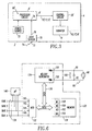
- a handheld electronic device 2 is shown.
- the device 2 includes a housing 4 and a suitable processor circuit 6 having an output 8 with a plurality of different states 10,12.
- a vibrator 14 is disposed within the housing 4.
- the vibrator 14 is adapted to vibrate the housing 4 at a plurality of different intensities 16,18.
- a control circuit 20 is adapted to activate the vibrator 14 at the different intensities 16,18 responsive to the respective different states 10,12 of the processor circuit output 8.
- a suitable power source 22 e.g., a battery
- Non-limiting examples of a handheld electronic device are disclosed in U.S. Patent Nos. 6,452,588; and 6,489,950, which are incorporated by reference herein.
- the processor circuit 6 may include a plurality of different operating modes (e.g., device in-use; device idle; device navigation in progress).
- the different states 10,12 of the processor circuit output 8 may correspond to some or all of those different operating modes.
- the control circuit 20 may activate the vibrator 14 at the different intensities 16,18 corresponding to such some or all of the different operating modes.
- FIG. 2 shows another handheld electronic device 32.
- the device 32 includes a housing 34 and a suitable processor circuit 36 having an output 38 with a plurality of different states 40,41,42.
- a vibrator 44 is disposed within the housing 34.
- the vibrator 44 is adapted to vibrate the housing 34 at a plurality of different intensities 46,47,48.
- a control circuit 50 is adapted to activate the vibrator 44 at the different intensities 46,47,48 responsive to the respective different states 40,41,42 of the processor circuit output 38.
- a suitable power source 52 is adapted to power one or more of the processor circuit 36, the vibrator 44 and the control circuit 50.
- a suitable input circuit 54 e.g., a user input device; a keyboard
- a suitable output circuit 56 e.g., a user output device; a display
- the housing 34 is adapted to optionally engage a holster 58.
- a sensor 60 includes an input 62 adapted to sense engagement of the housing 34 with the holster 58 and an output 64 responsive to such sensed engagement.
- the processor circuit 36 includes an input 66 receiving the sensor output 64.
- Examples of the sensor 60 include a proximity sensor (e . g ., sensing that the housing 34 is suitably proximate the holster 58), a light sensor (e.g., sensing a corresponding light source (not shown) in the holster 58; sensing an absence of light when the device 32 is in the holster 58), a capacitive sensor (e.g., sensing a capacitance associated with the device 32 engaging the holster 58), and separable contacts (e.g., which are closed when they engage an electrical conductor (not shown) of the holster 58).
- a proximity sensor e. g ., sensing that the housing 34 is suitably proximate the holster 58
- a light sensor e.g., sensing a corresponding light source (not shown) in the holster 58; sensing an absence of light when the device 32 is in the holster 58
- a capacitive sensor e.g., sensing a
- firmware 68 of the processor circuit 36 preferably automatically determines the different states 40,41,42, in order to select between the vibration intensities 46,47,48 based upon detection of one or more sensed events.
- the firmware 68 employs the input 66 receiving the sensor output 64 to decide if the device 32 is "in-holster” or "out-of-holster".
- three states may be established based on whether the device 32 was sensed as being: (1) "in-holster”; (2) “out-of-holster", or (3) "out-of-holster” plus the condition of being "in-use” ( e . g ., when the user inputs to the input circuit 54, such as, for example, by typing on a keyboard (not shown)).
- Key entry and/or user interface navigation triggers may also be employed to determine the third state of being "in-use” (e . g ., "out-of-holster" and the user is typing; the sensor 60 is a capacitive sensor that senses human touch).
- the device firmware 68 would presume the "in-use” state (e.g., state 42) and could, thereby, cause the control circuit 50 to automatically switch to a different vibration intensity (e.g., from intensity 47 to intensity 48).
- the output 38 switches back to appropriate state of "in-holster” or "out-of-holster” (e . g ., state 40 or state 41) and the corresponding vibration intensity (e.g., intensity 46 or intensity 47). For example, this transition may occur whenever the device 32 goes into a slow-clock or sleep state.
- the user may prefer a relatively reduced intensity of vibration as compared to a relatively increased intensity of vibration when "in-holster".
- the user may prefer a relatively lower intensity of vibration while holding the device.
- the input circuit 54 may include a microphone (not shown).
- the firmware 68 may determine if the handheld electronic device 32 is "in-use” based on input of a detected sound from the microphone to the processor circuit 36.
- the output circuit 56 may include a speaker (not shown).
- the firmware 68 may determine if the handheld electronic device 32 is "in-use” based upon an output from the processor circuit 36 to the speaker.
- the input circuit 54 may include a plurality of keys (not shown).
- the firmware 68 may determine if the handheld electronic device 32 is "in-use” based upon detected activity from one or more of the keys.
- the firmware 68 may determine if the handheld electronic device 32 is not "in-use” based upon a predetermined period of time of no detected activity from the keys of Example 5.
- the firmware 68 may cooperate with the input circuit 54, in order to provide the user with a user selection of "intelligent vibration" being on or off. If off, then the "intelligent vibration" selection is deactivated (e.g., by output state 69) and the device 32 only vibrates with a corresponding constant vibration intensity 69A. Otherwise, if the "intelligent vibration" selection is on and activated, then the control circuit 50 automatically causes the vibrator 44 to vibrate at one of the different vibration intensities 46,47,48 depending on the corresponding respective states 40,41,42 of the device 32 ( e . g ., in-holster; out-of-holster; out-of-holster and in-use).
- FIG. 3 another handheld electronic device 2' is somewhat similar to the device 2 of Figure 1.
- the device 2' includes a light sensor 70 having an input 72 adapted to sense ambient light 74 and an output 76 responsive to such sensed ambient light.
- the processor circuit 6' includes an input 78 receiving the sensor output 76.
- the control circuit 20' of Figure 3 includes the light sensor 70, which is adapted to sense a plurality of different light intensity levels (e.g., the device 2' is stored in an object (not shown), such as, for example, a briefcase or a purse; the device 2' is left sitting open in a lighted room (not shown)).
- the processor circuit 6' includes firmware 68' adapted to determine if the device 2' is in-use (e.g., as was discussed above in connection with Example 2) and to output, responsive to the input 78 and whether the device 2' is in-use, a corresponding one of the different states 10',11 ',12' of the output 8' thereof.
- the control circuit 20' activates the vibrator 14 at one of the different vibration intensities 16',17',18' corresponding to the respective different states 10',11',12'.
- user selectable vibration intensities may be automatically switched based on whether the device 2' is sensed as being: (1) “in-use” (e.g., when the user is typing on a keyboard, talking into a microphone and/or listening to a speaker); (2) "non-use” and being stored in something (e.g., a purse; a briefcase); or (3) "non-use” and not being stored (e.g., sitting open on a table or counter in a lighted room).
- the user may select, for example, a relatively lower vibration intensity while holding the device 2' for (1) "in-use” versus (3) a detected "non-use”. Otherwise, if detected (e.g., through the light intensity sensor 70) as (2) "non-use” and being stored in something, then the user may set the vibration intensity to the relatively highest level.
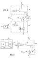
- a handheld electronic device vibrator drive control circuit 80 is shown.
- a handheld electronic device processor circuit ( ⁇ P) 82 includes a digital output 84.
- a handheld electronic device vibrator 86 includes a motor 88 having a first input terminal 90 and a second input terminal 92.
- the control circuit 80 includes a first circuit 94 adapted to output a substantially constant voltage 96 from a suitable supply voltage (+V) 97 to the motor first input terminal 90, and a second circuit 98 adapted to selectively enable the motor second input terminal 92 responsive to the ⁇ P digital output 84.
- the ⁇ P 82 is adapted to pulse-width modulate the digital output 84 at a selectable duty cycle (A/B), which corresponds to the motor voltage 100.
- the motor 88 is adapted to rotate at a speed based upon the substantially constant voltage 100, which corresponds to the duty cycle of the pulse-width modulated (PWM) digital output 84.
- PWM pulse-width modulated
- the intensity of the vibrator 86 varies directly with the motor voltage 100, which varies directly with the duty cycle (A/B) of the PWM digital output 84. No vibration occurs when the output 84 has about zero duty cycle.
- the second circuit 98 may be part of the ⁇ P 82.
- the PWM output 84 may be provided by employing a suitable PWM output port (e.g., from a processor circuit or from an integrated circuit such as, for example, a melody integrated circuit).
- a suitable PWM output port e.g., from a processor circuit or from an integrated circuit such as, for example, a melody integrated circuit.
- the PWM control port is an open drain that can sink suitable maximum motor current (e . g ., typically about 150 mA).
- suitable maximum motor current e. g ., typically about 150 mA
- a power FET, transistor, or the circuit 98 Figure 4 is employed to drive the relatively high motor current.
- the PWM output 84 may provide a series of step resolutions, typically about 128, in order that the duty cycle and the average motor voltage 100 can be suitably varied.
- the duty cycle of the PWM output 84, the calculated motor voltage, the measured motor voltage, the measured motor current and the measured motor revolutions per minute (RPM) of the motor 88 are shown in Table 1.
- the voltage 96 is about 3.3 VDC.
- Another alternative is to set the voltage 97 to about 3.3 VDC, and to adjust the voltage controlled current source circuit 94 to provide the voltage 96 at about 1.7 VDC.
- the resulting duty cycle can be varied from about 50% to about 100% to ensure the voltage across the vibrator motor 88 would never exceed the maximum rated voltage for this specific motor.
- the motor 88 is guaranteed to start if the duty cycle is greater than about 30%, although, after it is running, the duty cycle may be reduced to about 20%.
- the vibrator motor 88 response to the change in the duty cycle is almost instantaneous.
- the motor current will be at about 50 mA and, then, the power employed by the vibrator 86 is about 50 mW. If the vibrator 86 is driven with straight 1.5 VDC, or closer to about 45% PWM duty cycle, then the motor current is about 82 mA and the power is about 123 mW. Hence, the power savings at about 30% PWM duty cycle could be about 73 mW, which is a relatively large amount.
- the handheld electronic device vibrator 86 includes the motor 88 having the first and second input terminals 90,92.
- the output 112 of a processor circuit 114 is a digital-to-analog output with a voltage 116.
- the control circuit 110 includes an input 118 of the digital-to-analog output 112 of the processor circuit 114 and an output 120 to the input terminal 90 of the motor 88.
- the processor circuit 114 which includes a suitable microcontroller ( ⁇ C) 122 and a digital-to-analog converter (DAC) 124, is adapted to change the voltage 116 of the digital-to-analog output 112.
- the control circuit 110 is adapted to responsively change the motor voltage 100.
- the motor 88 rotates at a speed (or stops rotation) corresponding to the voltage 100 thereof.
- the user may be presented (e.g., through output circuit 56 of Figure 2) with a range of vibration intensities from relatively low to relatively high.
- the lowest setting represents the minimum duty cycle required to generate enough RMS voltage across the motor 88 ( Figures 4 and 5), in order for the vibrator 86 to operate (e.g., for the PWM drive control circuit 80 of Figure 4 it may be about 30% duty cycle; for the direct linear drive control circuit 110 of Figure 5, it may be about 1.1 VDC). Since most motors require a suitable initial start-up current, the control circuits 80,110 would be directed to provide this for a suitable time (e.g., a few milliseconds). After the motor 88 is turning, the motor's average voltage level can be reduced. The highest setting would represent the maximum duty cycle permitted (e . g ., a duty cycle as permitted by vibrator RPM and as permitted by maximum allowed average RMS voltage).
- the motor load current is about 130 mA
- the motor speed is about 10,909 RPM
- the supply voltage 96 is about 1.3 VDC.
- FIG. 6 shows another handheld electronic device vibrator drive control circuit 130.
- the circuit 130 may be formed from a conventional melody integrated circuit or from discrete components.
- the circuit 130 includes a microcontroller unit (MCU) 132, a suitable memory 134, a melody generator 136 and a data bus 138.
- the MCU 132 receives state information 139 on inputs 140,142,144,146 from a microprocessor ( ⁇ P) 148 or from the processor circuits 6 and 36 of respective Figures 1 and 2.
- ⁇ P microprocessor
- the MCU 132 communicates with the memory 134 and the melody generator 136 over the data bus 138.
- the memory 134 includes a plurality of sets of melody parameters (M1, M2, M3, M4) 148,150,152,154 corresponding to the respective inputs (STATE 1, STATE 2, STATE 3, STATE 4) 140,142,144,146.
- the MCU 132 responsively transfers the corresponding set of the melody parameters 148,150,152,154 to the melody generator 136.
- the melody generator 136 responsively generates PWM outputs 156 (PWM+) and 158 (PWM-), in order to provide a suitable voltage versus time waveform 160 that drives the vibrator 86.
- the RPM of the motor 88 follows the waveform 160, such that the resulting variable vibration versus time response of the vibrator 86 mimics the melody that corresponds to the state information 139 of the ⁇ P 148.
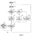
- a flowchart of a routine 170 executed by the processor circuit 36 ( e . g ., including a ⁇ P) of Figure 2 is shown.
- a main loop 173 of the handheld electronic device 32 is executed at 173.
- the main loop 173 may include a wide range of one or more applications, such as, for example, any suitable handheld electronic device function(s), word processing applications, spreadsheet applications, calendar functions, address book functions, journal entry functions, notification functions ( e .
- e-mail messages telephone messages, telephone calls, SMS messages, calendar events, meeting notifications, personal alerts, alarms, warnings, stock quotes, news bulletins, other web browser events), task list functions, alarm functions, web browser functions, e-mail functions, telephone functions and/or SMS messaging functions.
- notifiable events include, for example, e-mail messages, telephone messages, telephone calls, SMS messages, calendar events, meeting notifications, personal alerts, alarms, warnings, stock quotes, news bulletins and other web browser events. If so, then at 186, the vibrator 44 is activated through the control circuit 50 with one of the different intensities 46,47,48 ( Figure 2), which corresponds to the states of steps 176,180,182. Finally, after either 184 or 186, the main loop 173 is repeated. This permits the handheld electronic device 32 to employ a plurality of different vibration intensity levels, and to selectively vibrate such device at those different vibration intensity levels.
- Figure 8 shows a flowchart of a routine 190 executed by the processor circuit 6' ( e . g ., including a ⁇ P) of Figure 3.
- a main loop 193 of the handheld electronic device 2' is executed at 193.
- the main loop 193 may be the same or similar to the main loop 173 of Figure 7.
- the main loop 193 determines a notifiable event (e.g., as was discussed above in connection with step 173 of Figure 7). If so, then at 206, the vibrator 14 is activated through the control circuit 20' with one of the different intensities 16',17',18' ( Figure 3), which corresponds to the states of steps 196,200,202. Finally, after either 204 or 206, the main loop 193 is repeated.
- a notifiable event e.g., as was discussed above in connection with step 173 of Figure 7.
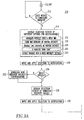
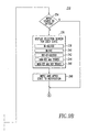
- Figures 9A-9B show a configuration routine 210, which may be executed as part of the main loop 173 of Figure 7 or the main loop 193 of Figure 8.
- this configuration may apply to one, some or all of the notifiable events (e.g., as determined at 184 of Figure 7 or 204 of Figure 8).
- a common configuration may be applied to all of the notifiable events or unique configurations may be applied to one or more of those notifiable events.
- a selection screen is displayed (e.g., through the output circuit 56 of Figure 2) including different options for the notification(s).
- Those options may include one or more of the following methods for employing the vibrator: (1) change the vibration intensity over a predetermined time period 216; (2) employ fixed time divisions of varying vibration intensity 218; (3) employ variable time divisions of varying vibration intensity 220; (4) employ a vibrator "ring tone" 222 (e.g., a "melody” as was discussed above in connection with Figure 6; any one, two or all three of items (1), (2) and/or (3), above); and (5) employ a fixed vibration intensity setting 224.
- ring tone e.g., a "melody” as was discussed above in connection with Figure 6; any one, two or all three of items (1), (2) and/or (3), above
- (5) employ a fixed vibration intensity setting 224.
- one of the options 216,218,220,222,224 is input and applied to the notification(s) of interest.
- a selection screen e.g., a menu of items on a display screen of the output circuit 56 of Figure 2 is displayed including all of the possible vibration intensity values.
- one of the default vibration intensity values is input (e.g., by selecting one of the different vibration intensity levels from a suitable user input device, such as a keyboard (not shown), of the input circuit 54 of Figure 2; as discussed below in connection with Example 16) and applied to the notification(s) of interest.
- step 232 new vibration intensity configurations are downloaded by the handheld electronic device 32 (e . g ., employing a wireless port (not shown) or the Internet (not shown)) before step 228 is executed.
- the handheld electronic device 32 e . g ., employing a wireless port (not shown) or the Internet (not shown)
- step 228 is executed.
- Those states may include one or more of: (1) in-holster 238; (2) in-use 240; (3) out-of-holster 242; (4) non-use and stored 244; and (5) non-use and not stored 246.
- the states 238,244 might correspond to relatively high values of vibration intensity
- the states 242,246 might correspond to a relatively moderate values of vibration intensity
- the in-use state 240 might correspond to a relatively low value of vibration intensity.
- those states could be the same or different as applied to the different types of notifiable events.
- the states are input and are applied to the notification(s).
- the in-use determination, at 178 and 198, respectively, may include the detection of the activation of another routine in the respective main loops 173 and 193.
- this might include a navigation trigger where the user activates one routine from another.
- a key (not shown) pressed or a navigation event interrupt routine (not shown) is invoked when user input is determined (e.g., by input circuit 54 of Figure 2).
- a software flag (not shown) would then be set to indicate or to send a message of "in-use" for the first routine to act upon.
- the input circuit 54 may include a suitable user input device 254 (e.g., a keypad; an input module; one or more main navigation keys of a keyboard; a mini-joystick; a track wheel) including a first position and a second position
- the output circuit 56 may include a suitable display device 256 ( e . g ., a display having a bar-meter; an output module).
- the user input device 254 is employed to adjust the display device 256, which tracks changes in the vibration intensity level of the vibrator 44.
- the track wheel may be employed to adjust a bar-meter presented on the display device 256.
- the bar meter tracks changes to the duty cycle of the vibrator 86. Turning the track wheel clockwise, for example, would increase the PWM duty cycle (and, thus, the vibration intensity), and turning the track wheel counter-clockwise would decrease the PWM duty cycle (and, thus, the vibration intensity).
- the display device 256 may present the user with a discrete range or a continuous range of the different vibration intensity levels.
- the user may employ the user input device 254 to select one of the different vibration intensity levels from the range.
- the handheld electronic devices 32 may include a plurality of different operating states, such as 238,240,242,244,246 and/or other operating modes, and the routines 170,190 automatically determine a current one of the different operating states, and automatically vibrate the corresponding handheld electronic device at a corresponding one of the different vibration intensity levels based upon the determined current one of the different operating states.
- different operating states such as 238,240,242,244,246 and/or other operating modes
- the different operating modes may include executing a first application routine (e.g., e-mail), and executing a second different application routine (e.g., calendar).
- a first application routine e.g., e-mail
- a second different application routine e.g., calendar
- notifications associated with the first application routine may have a different vibration intensity (e.g., greater; smaller) with respect to notifications associated with the second different application routine ( e . g ., calendar events).
- the user may choose one of a set of customized vibration "ring tones" depending on the state of the handheld electronic devices 32 ( Figure 2) and 2' ( Figure 3) and/or the type of notification.
- the user may download from a selection of predetermined vibration intensity settings from a server (not shown). These settings may include further variations of device default vibration intensity settings to time variable and/or vibration intensity variable settings that mimic a musical melody.
- the server may include a suitable utility (not shown) to translate a song melody to the time variable and vibration intensity variable settings.
- the user may choose to have the vibrator notification gradually increase in intensity by: (1) a continuous gradual increase in vibration intensity; (2) a series of increasingly intense "pulses" of vibration; or (3) a continuous gradual increase in vibration intensity for only a predetermined time.
- the various selected vibration intensity values, options and state information settings may advantageously be input by the user through a user profile screen (not shown) of the input circuit 54 of Figure 2.
- Option 216 of Figure 9A may continuously change the selected vibration intensity level for corresponding notification event(s) over time or over a predetermined time interval. This may be based on a song melody and may be implemented, for example, with the control circuit 130 of Figure 6.
- Option 218 of Figure 9A may vibrate the handheld electronic device with a plurality of discrete vibration pulses. These discrete vibration pulses have different vibration intensities and constant vibration pulse lengths. This may be based on a song melody and may be implemented, for example, with the control circuit 130 of Figure 6.
- Option 218 of Figure 9A may include increasing the selected one of the different vibration intensity levels by employing a continuous gradual increase in vibration intensity, such as, for example, a series of increasingly intense "pulses" of vibration.
- Option 220 of Figure 9A may vibrate the handheld electronic device with a plurality of discrete vibration pulses.
- These discrete vibration pulses may have the same or different vibration intensities and may have a plurality of different vibration pulse lengths (e.g., mimicking Morse Code).
- Option 220 of Figure 9A may include changing both the time of vibration and the intensity of vibration of the handheld electronic device over time. Hence, successive pulses of vibration have both different pulse widths and different vibration intensities.
- Option 222 of Figure 9A provides a time variable vibration intensity that mimics a "ring tone” (i.e., including a plurality of vibrator intensities that vary over time).
- a "ring tone” may be locally defined by the handheld electronic device or may be downloaded to it.
- the user may choose one of a set of customized vibration tones depending on the type of notification event (e.g., e-mail; calendar; telephone; alarm) and/or the state of the handheld electronic device (e . g ., in-use; holstered; out-of-holster; non-use and stored; non-use and not stored).
- the type of notification event e.g., e-mail; calendar; telephone; alarm
- the state of the handheld electronic device e . g ., in-use; holstered; out-of-holster; non-use and stored; non-use and not stored.
- Customized vibration tones may take the form of vibrations, which vary differently over time by: (1) continuously changing the intensity over time, (2) sending fixed-time pulses each with different intensities (that could be based on a song melody), (3) sending a series of pulses of varying length (e.g., mimicking Morse Code), and/or (4) all of items (1)-(3).
- the user may selectively disable through the input circuit 54 (Figure 2): (1) all vibration of the handheld electronic device; (2) vibration of the handheld electronic device for one or more notification events; (3) one, some or all of the options 216,218,220,222,224 of Figure 9A; and/or (4) cause all notification events to be notified at the same vibration level.
- the user may manually deactivate the vibration before it becomes unnecessarily intense. For example, by starting with a relatively "soft" vibration intensity and by increasing that intensity over time, the user can then deactivate the vibration (e.g., through the input circuit 54 of Figure 2) before the vibration intensity becomes unnecessarily intense (e.g., such as when the user is in a meeting).
- the user may un-holster the device 32 from the holster 58 of Figure 2, in order to deactivate the constant or increasing vibration.
- the user may disable or enable escalating intensity of vibrator notification for one, some or all of the different types of notification events.
- the configuration routine 210 of Figures 9A-9B may present the user with a list (not shown) for user selection of "vibrator patterns” each of which may include one or more implementation options (e.g., steps 216, 218, 220, 222, 224).
- This list may include plural vibrator patterns (e . g ., "vibrator_pattern1"; vibrator_pattern2").
- the corresponding vibrator 44 Figure 2 would respond with the appropriate response of vibration intensity(s) that is currently highlighted in the list (e.g., through output circuit 56 of Figure 2). In this manner, the user may intuitively select the desired vibrator pattern by being able to "feel" it first.
- a handheld electronic device 250 includes a suitable processor 252, a suitable power source 254 powering such processor, a system memory 256 for the processor and user input/output circuits 258.
- a melody integrated circuit (IC) 260 interfaces the processor 252 through a suitable interface 261 (e.g., a parallel bus; a serial interface).
- the melody IC 260 provides a vibrator drive control circuit for the vibrator 86 of Figure 6 and a sound output port through analog output 262.
- the analog output 262 is input by a multiplexer 263 that feeds an amplifier 264, which drives a speaker 266.
- the multiplexer 263 is also fed by an analog output from a voiceband codec circuit 270 that drives another speaker 268.
- the output/input 271 of the circuit 270 is input/output by a suitable serial interface (I/F) 272 for input/output by the processor 252.
- I/F serial interface
- the melody IC 260 is a model ML2870AGD marketed by OKI Semiconductor of Tokyo, Japan.
- the melody IC 260 includes, for example, a CPU interface section (not shown) for the interface 261, a FIFO section (not shown), a hardware sequencer section (not shown), an LED/vibrator controller/driver section 274, an ADPCM MIDI decoder section 276 and a digital-to-analog converter (DAC) 278.
- the section 276 and DAC 278 cooperate to provide analog signals to the output 262 to drive the speaker 266.
- the section 274 provides an open drain PWM port output 280 for driving the vibrator 86.
- the PWM port output 280 is switched to the section 274. For example, when the output 280 is low, the vibrator 86 is on; when the output 280 is in a high impedance state, then the vibrator 86 is off.
- the processor 252 sends a new value to be written to the PWM vibrator register (not shown) of the section 274 through interface 261.
- Another open drain output 282 may be employed to control the on/off/color states of LED 284.
- the handheld electronic device 250 of Figure 10 may be a wireless handheld communication device including, as part of the circuits 258, a wireless communication port 286.
- Table 2 shows examples of "sensed" locations of a handheld electronic device and corresponding sample configurable vibration intensity levels (e.g., ranging from 0 (off) to 1 (low) to 5 (high)) for particular example applications.
- the user sets up one or more discrete profiles when in a meeting or when significant disturbances are sought to be avoided, in order that notifications are to be as quiet as possible.
- five example vibration intensities are shown, it will be appreciated that a wide range of different vibration intensity levels, types and counts may be employed.
- Notification Type Event In-Holster Out-of-Holster In-Use Stored Calendar - Spouse's birthday 5 4 3 5 Calendar - Meeting notification 3 2 1 5 E-mail - High priority e-mail while user is in a meeting (e.g., if user setup a "discrete" profile) 2 1 2 3 E-mail - Low priority e-mail while user is in a meeting ( e . g ., if user setup a "discrete” profile) 0 0 1 0 Telephone - Incoming call while user is in a meeting (e.g., if user setup a "discrete” profile) 2 1 2 3 E-mail-Normal priority 3 3 1 4 Telephone - Incoming call 4 3 2 5
- relatively higher vibration intensity level settings can typically be applied for a relatively shorter time duration than that of relatively lower vibration intensities, in order to be recognized by the user. For example, a 50 ms duration may suffice with a relatively higher intensity setting, but a 200 ms duration may be required with a relatively lower intensity for the user to sense the vibration.
- the operating mode of navigation in progress may include, for example, use of the vibrator 44 of Figure 2 during user navigation when employing the input and outputs circuits 54 and 56, respectively.
- the vibrator 44 may be briefly enabled at a particular vibration intensity as the user traverses across plural menu selections (not shown) of the output circuit 56.
- the user may select and configure the vibration intensity levels (e.g., one of two, three or more different vibration intensity levels).
- a 3 VDC motor such as 88
- the motor terminal 90 of Figure 4 would be electrically connected to about 3.3 VDC at 97 (+V) through a suitably small value of resistance (not shown), such that the voltage at the motor terminal 90 would be about 3 VDC. It will be appreciated, however, that a wide range of vibrator motor types and/or voltages may be employed.
- Figures 7, 8 and 9A-9B show a serial processing flow
- the invention is applicable to handheld electronic devices that may employ a multithreaded processing environment.
- the user may selectively adjust all of the vibration intensity levels by a predetermined or configurable increment or decrement value (e.g., +2; +1; -1; -2). It will be appreciated, however, that such an adjustment may be implemented by software, by a suitable digital circuit (not shown) or by suitable analog circuit (e.g., that adjusts the voltage 96 of Figure 4) (not shown).
- a predetermined or configurable increment or decrement value e.g., +2; +1; -1; -2
- the disclosed control circuits 20,20',50,80,110,130,260 permit different average and/or time variable voltages to appear across vibrator motor terminals, in order to create a range of vibration intensity levels through variable motor RPM. This permits a plurality of different vibration intensity levels and/or time variable vibration intensities to be provided for different notification events and/or for different handheld electronic device states.
- Adjustable vibration intensity levels give the user another option to improve his/her experience with handheld electronic devices.
- the user to provide decreased handheld device power consumption if, for example, the user is a relatively heavy device user and if the user chooses to employ a reduced vibration intensity notifications.
- the current drawn by the vibrator motor 88 ( Figures 4-6), while active, can be reduced proportionally to the vibrator motor RPM by lowering the required average voltage across the motor terminals.
- the invention gives the user a broader range of notification options versus a series of on/off vibrations, which are all at the same vibration intensity level. Furthermore, the user may personalize the vibration intensity to their own "sensitivity" level by selecting from a range of different vibration intensity level settings.
- control circuits 20,20',50,80,110,130,260 are disclosed, it will be appreciated that a wide range of analog, digital and/or processor-based circuits may be employed.
Landscapes
- Engineering & Computer Science (AREA)
- Signal Processing (AREA)
- Physics & Mathematics (AREA)
- General Physics & Mathematics (AREA)
- Telephone Function (AREA)
- Mobile Radio Communication Systems (AREA)
- Apparatuses For Generation Of Mechanical Vibrations (AREA)
- User Interface Of Digital Computer (AREA)
- Measuring Fluid Pressure (AREA)
- Measurement Of Mechanical Vibrations Or Ultrasonic Waves (AREA)
- Electric Clocks (AREA)
Priority Applications (7)
| Application Number | Priority Date | Filing Date | Title |
|---|---|---|---|
| EP04253154A EP1600907B1 (fr) | 2004-05-27 | 2004-05-27 | Dispositif électronique à main ayant un vibrateur avec des intensités de vibration différentes et un procédé pour faire vibrer un tel dispositif |
| AT04253154T ATE358861T1 (de) | 2004-05-27 | 2004-05-27 | Handgehaltene elektronische vorrichtung mit einem vibrator der mit verschiedenen intensitäten vibriert und vibrationsmethode dafür |
| DE602004005683T DE602004005683T2 (de) | 2004-05-27 | 2004-05-27 | Handgehaltene elektronische Vorrichtung mit einem Vibrator, der mit verschiedenen Intensitäten vibriert, und Vibrationsmethode dafür |
| SG200502872A SG117560A1 (en) | 2004-05-27 | 2005-05-04 | Handheld electronic device including vibrator having different vibration intensities and method for vibrating a handheld electronic device |
| CNB2005100743062A CN100501783C (zh) | 2004-05-27 | 2005-05-25 | 具有不同振动强度的振动器的手持电子设备及方法 |
| CA2508387A CA2508387C (fr) | 2004-05-27 | 2005-05-26 | Dispositif electronique portatif comprenant un vibromasseur avec differentes intensites de vibration, et methode vibratoire |
| HK06105327.7A HK1083381B (en) | 2006-05-06 | Handheld electronic device including vibrator having different vibration intensities and method for vibrating a handheld electronic device |
Applications Claiming Priority (1)
| Application Number | Priority Date | Filing Date | Title |
|---|---|---|---|
| EP04253154A EP1600907B1 (fr) | 2004-05-27 | 2004-05-27 | Dispositif électronique à main ayant un vibrateur avec des intensités de vibration différentes et un procédé pour faire vibrer un tel dispositif |
Publications (2)
| Publication Number | Publication Date |
|---|---|
| EP1600907A1 true EP1600907A1 (fr) | 2005-11-30 |
| EP1600907B1 EP1600907B1 (fr) | 2007-04-04 |
Family
ID=34930343
Family Applications (1)
| Application Number | Title | Priority Date | Filing Date |
|---|---|---|---|
| EP04253154A Expired - Lifetime EP1600907B1 (fr) | 2004-05-27 | 2004-05-27 | Dispositif électronique à main ayant un vibrateur avec des intensités de vibration différentes et un procédé pour faire vibrer un tel dispositif |
Country Status (6)
| Country | Link |
|---|---|
| EP (1) | EP1600907B1 (fr) |
| CN (1) | CN100501783C (fr) |
| AT (1) | ATE358861T1 (fr) |
| CA (1) | CA2508387C (fr) |
| DE (1) | DE602004005683T2 (fr) |
| SG (1) | SG117560A1 (fr) |
Cited By (10)
| Publication number | Priority date | Publication date | Assignee | Title |
|---|---|---|---|---|
| US7268290B2 (en) | 2002-11-27 | 2007-09-11 | Solutions For Thought, Llc | Tactile metronome |
| US7285101B2 (en) | 2005-05-26 | 2007-10-23 | Solutions For Thought, Llc | Vibrating transducer with provision for easily differentiated multiple tactile stimulations |
| EP2051154A1 (fr) | 2007-10-12 | 2009-04-22 | Research In Motion Limited | Dispositif électronique incluant un dispositif électronique portable doté d'un étui intelligent |
| US7554289B2 (en) | 2006-11-03 | 2009-06-30 | Research In Motion Limited | Apparatus and method for the power management of operatively connected batteries respectively on a handheld electronic device and a holder for the handheld electronic device |
| US7863862B2 (en) | 2007-10-12 | 2011-01-04 | Research In Motion Limited | Handheld electronic device with holster having a notification device |
| US8286095B2 (en) | 2009-01-15 | 2012-10-09 | Research In Motion Limited | Multidimensional volume and vibration controls for a handheld electronic device |
| EP2663062A1 (fr) * | 2012-05-08 | 2013-11-13 | BlackBerry Limited | Représentation non visuelle d'une valeur de jauge de courant d'un dispositif électronique sur un continuum |
| US8666453B2 (en) | 2009-09-03 | 2014-03-04 | Htc Corporation | Method of adjusting event prompt degree, and mobile electronic device and computer program product using the same |
| US9066310B2 (en) | 2012-05-08 | 2015-06-23 | Blackberry Limited | Non-visual representation of a current gauge value of an electronic device on a continuum |
| US20190108748A1 (en) * | 2014-09-02 | 2019-04-11 | Apple Inc. | Providing Priming Cues to a User of an Electronic Device |
Families Citing this family (7)
| Publication number | Priority date | Publication date | Assignee | Title |
|---|---|---|---|---|
| CN107277223B (zh) * | 2009-09-16 | 2021-07-13 | 宏达国际电子股份有限公司 | 调整事件提示程度的方法与其移动电子装置 |
| CN102753969B (zh) | 2010-02-09 | 2015-12-02 | 诺基亚公司 | 用于监视与移动终端机械接触的物体的特性的方法和装置 |
| CN104767870A (zh) * | 2014-01-07 | 2015-07-08 | 中兴通讯股份有限公司 | 一种消息响应的方法及装置 |
| US8941500B1 (en) * | 2014-01-23 | 2015-01-27 | Google Inc. | Somatosensory type notification alerts |
| US11159109B2 (en) * | 2016-12-16 | 2021-10-26 | Seiko Instruments Inc. | Control device for vibration generation device, electronic apparatus, and method of controlling vibration generation |
| CN112527120B (zh) * | 2020-12-24 | 2026-04-14 | 瑞声新能源发展(常州)有限公司科教城分公司 | 触觉反馈的转换方法、装置及计算机可读存储介质 |
| CN113269418B (zh) * | 2021-05-12 | 2024-06-18 | 北京京东乾石科技有限公司 | 设备检测方法、装置、设备及存储介质 |
Citations (6)
| Publication number | Priority date | Publication date | Assignee | Title |
|---|---|---|---|---|
| WO1991006932A1 (fr) * | 1989-11-06 | 1991-05-16 | Motorola, Inc. | Recepteur d'appels selectif |
| DE29707166U1 (de) * | 1997-04-11 | 1997-08-28 | Hillmann, Guido, 48143 Münster | Handytasche, die der/dem Angerufenen einen Anruf mitteilt, auch wenn der Signalton des Mobiltelefons ausgeschaltet ist |
| WO2002054363A1 (fr) * | 2000-12-29 | 2002-07-11 | Davor Petric | Commutation automatique entre une alerte d'appel par sonnerie et une alerte d'appel par vibrations |
| GB2378616A (en) * | 2001-08-11 | 2003-02-12 | Ubinetics Ltd | Dual alerting mobile device |
| GB2378617A (en) * | 2001-08-11 | 2003-02-12 | Ubinetics Ltd | Mobile device vibrating in response to a predetermined condition |
| US20040067780A1 (en) * | 2000-12-27 | 2004-04-08 | Niko Eiden | Vibrating portable electronic device, method of vibrating a portable electronic device and method of messaging by vibrating a portable electronic device |
-
2004
- 2004-05-27 DE DE602004005683T patent/DE602004005683T2/de not_active Expired - Lifetime
- 2004-05-27 AT AT04253154T patent/ATE358861T1/de not_active IP Right Cessation
- 2004-05-27 EP EP04253154A patent/EP1600907B1/fr not_active Expired - Lifetime
-
2005
- 2005-05-04 SG SG200502872A patent/SG117560A1/en unknown
- 2005-05-25 CN CNB2005100743062A patent/CN100501783C/zh not_active Expired - Lifetime
- 2005-05-26 CA CA2508387A patent/CA2508387C/fr not_active Expired - Lifetime
Patent Citations (6)
| Publication number | Priority date | Publication date | Assignee | Title |
|---|---|---|---|---|
| WO1991006932A1 (fr) * | 1989-11-06 | 1991-05-16 | Motorola, Inc. | Recepteur d'appels selectif |
| DE29707166U1 (de) * | 1997-04-11 | 1997-08-28 | Hillmann, Guido, 48143 Münster | Handytasche, die der/dem Angerufenen einen Anruf mitteilt, auch wenn der Signalton des Mobiltelefons ausgeschaltet ist |
| US20040067780A1 (en) * | 2000-12-27 | 2004-04-08 | Niko Eiden | Vibrating portable electronic device, method of vibrating a portable electronic device and method of messaging by vibrating a portable electronic device |
| WO2002054363A1 (fr) * | 2000-12-29 | 2002-07-11 | Davor Petric | Commutation automatique entre une alerte d'appel par sonnerie et une alerte d'appel par vibrations |
| GB2378616A (en) * | 2001-08-11 | 2003-02-12 | Ubinetics Ltd | Dual alerting mobile device |
| GB2378617A (en) * | 2001-08-11 | 2003-02-12 | Ubinetics Ltd | Mobile device vibrating in response to a predetermined condition |
Cited By (24)
| Publication number | Priority date | Publication date | Assignee | Title |
|---|---|---|---|---|
| US7268290B2 (en) | 2002-11-27 | 2007-09-11 | Solutions For Thought, Llc | Tactile metronome |
| US7304230B2 (en) | 2002-11-27 | 2007-12-04 | Solutions For Thought, Llc | Multiple channel metronome |
| US7390955B2 (en) | 2002-11-27 | 2008-06-24 | Solutions For Thought, Llc | Metronome with wireless transducer |
| US7422564B2 (en) | 2002-11-27 | 2008-09-09 | Solutions For Thought, Llc | Tactile rhythm generator |
| US7285101B2 (en) | 2005-05-26 | 2007-10-23 | Solutions For Thought, Llc | Vibrating transducer with provision for easily differentiated multiple tactile stimulations |
| US7554289B2 (en) | 2006-11-03 | 2009-06-30 | Research In Motion Limited | Apparatus and method for the power management of operatively connected batteries respectively on a handheld electronic device and a holder for the handheld electronic device |
| US7847514B2 (en) | 2006-11-03 | 2010-12-07 | Research In Motion Limited | Apparatus and method for the power management of operatively connected batteries respectively on a handheld electronic device and a holder for the handheld electronic device |
| US7986123B2 (en) | 2006-11-03 | 2011-07-26 | Research In Motion Limited | Apparatus and method for the power management of operatively connected batteries respectively on a handheld electronic device and a holder for the handheld electronic device |
| EP2051154A1 (fr) | 2007-10-12 | 2009-04-22 | Research In Motion Limited | Dispositif électronique incluant un dispositif électronique portable doté d'un étui intelligent |
| US7863862B2 (en) | 2007-10-12 | 2011-01-04 | Research In Motion Limited | Handheld electronic device with holster having a notification device |
| EP2309361A1 (fr) * | 2007-10-12 | 2011-04-13 | Research In Motion Limited | Dispositif électronique incluant un dispositif électronique portable doté d'un étui intelligent |
| US8179093B2 (en) | 2007-10-12 | 2012-05-15 | Research In Motion Limited | Handheld electronic device with holster having a notification device |
| US8286095B2 (en) | 2009-01-15 | 2012-10-09 | Research In Motion Limited | Multidimensional volume and vibration controls for a handheld electronic device |
| US8527902B2 (en) | 2009-01-15 | 2013-09-03 | Blackberry Limited | Multidimensional volume and vibration controls for a handheld electronic device |
| US8666453B2 (en) | 2009-09-03 | 2014-03-04 | Htc Corporation | Method of adjusting event prompt degree, and mobile electronic device and computer program product using the same |
| TWI473490B (zh) * | 2009-09-03 | 2015-02-11 | Htc Corp | 調整事件提示程度的方法與其行動電子裝置及電腦程式產品 |
| US8995983B2 (en) | 2009-09-03 | 2015-03-31 | Htc Corporation | Method of adjusting event prompt degree and mobile electronic device and computer program product using the same |
| EP2663062A1 (fr) * | 2012-05-08 | 2013-11-13 | BlackBerry Limited | Représentation non visuelle d'une valeur de jauge de courant d'un dispositif électronique sur un continuum |
| US9066310B2 (en) | 2012-05-08 | 2015-06-23 | Blackberry Limited | Non-visual representation of a current gauge value of an electronic device on a continuum |
| US20190108748A1 (en) * | 2014-09-02 | 2019-04-11 | Apple Inc. | Providing Priming Cues to a User of an Electronic Device |
| CN109976517A (zh) * | 2014-09-02 | 2019-07-05 | 苹果公司 | 向电子设备的用户提供预激提示 |
| US10984649B2 (en) * | 2014-09-02 | 2021-04-20 | Apple Inc. | Providing priming cues to a user of an electronic device |
| AU2020202367B2 (en) * | 2014-09-02 | 2022-04-07 | Apple Inc. | Providing priming cues to a user of an electronic device |
| US11521477B2 (en) | 2014-09-02 | 2022-12-06 | Apple Inc. | Providing priming cues to a user of an electronic device |
Also Published As
| Publication number | Publication date |
|---|---|
| CA2508387C (fr) | 2011-01-25 |
| CN1707533A (zh) | 2005-12-14 |
| CN100501783C (zh) | 2009-06-17 |
| ATE358861T1 (de) | 2007-04-15 |
| SG117560A1 (en) | 2005-12-29 |
| DE602004005683T2 (de) | 2007-12-27 |
| CA2508387A1 (fr) | 2005-11-27 |
| EP1600907B1 (fr) | 2007-04-04 |
| DE602004005683D1 (de) | 2007-05-16 |
| HK1083381A1 (en) | 2006-06-30 |
Similar Documents
| Publication | Publication Date | Title |
|---|---|---|
| US7019622B2 (en) | Handheld electronic device including vibrator having different vibration intensities and method for vibrating a handheld electronic device | |
| EP1600907B1 (fr) | Dispositif électronique à main ayant un vibrateur avec des intensités de vibration différentes et un procédé pour faire vibrer un tel dispositif | |
| KR100371181B1 (ko) | 휴대용 기기의 절전방법 | |
| JP3438693B2 (ja) | 表示部付き電子機器 | |
| KR100455991B1 (ko) | 이동 단말기의 액정 표시부 백라이트 제어 장치 | |
| US8179202B2 (en) | Multiple pulse width modulation | |
| US6725064B1 (en) | Portable terminal device with power saving backlight control | |
| US8710965B2 (en) | Devices, systems, and methods for tactile feedback and input | |
| CN1286249C (zh) | 振动报警装置 | |
| WO2009146857A2 (fr) | Interface utilisateur, dispositif et procédé pour un mode de fonctionnement amélioré | |
| JP2002300235A (ja) | 知覚可能な効果を移動局のユーザーに示す方法及び移動局 | |
| US9781679B2 (en) | Electronic systems and method of operating electronic systems | |
| CN1658182B (zh) | 用于修改电子设备中通知的方法 | |
| HK1083381B (en) | Handheld electronic device including vibrator having different vibration intensities and method for vibrating a handheld electronic device | |
| CN101651871A (zh) | 具有省电功能的电子装置及方法 | |
| EP2050261B1 (fr) | Écran d'affichage graphique | |
| JP2005136674A (ja) | 移動体端末装置 | |
| JP3330819B2 (ja) | 他励式ブザー駆動回路 | |
| KR100747892B1 (ko) | 이동 단말기에서의 진동 장치 | |
| KR100628068B1 (ko) | 이동 통신 단말기의 배터리 상태에 따른 경고 장치 및 방법 | |
| KR970068235A (ko) | 모터의 진동제어방법 및 그 방법을 이용한 휴대용 전자제품 | |
| JPH1039272A (ja) | 液晶表示器のバックライト装置 | |
| KR0134802Y1 (ko) | 모니터의 신호 무입력시 경보회로 | |
| KR960027429A (ko) | 무선호출장치의 호출음 발생장치 및 그 방법 | |
| JP2002077330A (ja) | 携帯電話装置 |
Legal Events
| Date | Code | Title | Description |
|---|---|---|---|
| PUAI | Public reference made under article 153(3) epc to a published international application that has entered the european phase |
Free format text: ORIGINAL CODE: 0009012 |
|
| 17P | Request for examination filed |
Effective date: 20050923 |
|
| AK | Designated contracting states |
Kind code of ref document: A1 Designated state(s): AT BE BG CH CY CZ DE DK EE ES FI FR GB GR HU IE IT LI LU MC NL PL PT RO SE SI SK TR |
|
| AX | Request for extension of the european patent |
Extension state: AL HR LT LV MK |
|
| REG | Reference to a national code |
Ref country code: HK Ref legal event code: DE Ref document number: 1083381 Country of ref document: HK |
|
| AKX | Designation fees paid |
Designated state(s): AT BE BG CH CY CZ DE DK EE ES FI FR GB GR HU IE IT LI LU MC NL PL PT RO SE SI SK TR |
|
| AXX | Extension fees paid |
Extension state: MK Payment date: 20060518 Extension state: LT Payment date: 20060518 Extension state: LV Payment date: 20060518 Extension state: HR Payment date: 20060518 Extension state: AL Payment date: 20060518 |
|
| GRAP | Despatch of communication of intention to grant a patent |
Free format text: ORIGINAL CODE: EPIDOSNIGR1 |
|
| GRAS | Grant fee paid |
Free format text: ORIGINAL CODE: EPIDOSNIGR3 |
|
| GRAA | (expected) grant |
Free format text: ORIGINAL CODE: 0009210 |
|
| AK | Designated contracting states |
Kind code of ref document: B1 Designated state(s): AT BE BG CH CY CZ DE DK EE ES FI FR GB GR HU IE IT LI LU MC NL PL PT RO SE SI SK TR |
|
| AX | Request for extension of the european patent |
Extension state: AL HR LT LV MK |
|
| PG25 | Lapsed in a contracting state [announced via postgrant information from national office to epo] |
Ref country code: CH Free format text: LAPSE BECAUSE OF FAILURE TO SUBMIT A TRANSLATION OF THE DESCRIPTION OR TO PAY THE FEE WITHIN THE PRESCRIBED TIME-LIMIT Effective date: 20070404 Ref country code: LI Free format text: LAPSE BECAUSE OF FAILURE TO SUBMIT A TRANSLATION OF THE DESCRIPTION OR TO PAY THE FEE WITHIN THE PRESCRIBED TIME-LIMIT Effective date: 20070404 Ref country code: FI Free format text: LAPSE BECAUSE OF FAILURE TO SUBMIT A TRANSLATION OF THE DESCRIPTION OR TO PAY THE FEE WITHIN THE PRESCRIBED TIME-LIMIT Effective date: 20070404 Ref country code: SI Free format text: LAPSE BECAUSE OF FAILURE TO SUBMIT A TRANSLATION OF THE DESCRIPTION OR TO PAY THE FEE WITHIN THE PRESCRIBED TIME-LIMIT Effective date: 20070404 |
|
| REG | Reference to a national code |
Ref country code: GB Ref legal event code: FG4D |
|
| REG | Reference to a national code |
Ref country code: CH Ref legal event code: EP |
|
| REF | Corresponds to: |
Ref document number: 602004005683 Country of ref document: DE Date of ref document: 20070516 Kind code of ref document: P |
|
| REG | Reference to a national code |
Ref country code: IE Ref legal event code: FG4D |
|
| PG25 | Lapsed in a contracting state [announced via postgrant information from national office to epo] |
Ref country code: SE Free format text: LAPSE BECAUSE OF FAILURE TO SUBMIT A TRANSLATION OF THE DESCRIPTION OR TO PAY THE FEE WITHIN THE PRESCRIBED TIME-LIMIT Effective date: 20070704 |
|
| PG25 | Lapsed in a contracting state [announced via postgrant information from national office to epo] |
Ref country code: ES Free format text: LAPSE BECAUSE OF FAILURE TO SUBMIT A TRANSLATION OF THE DESCRIPTION OR TO PAY THE FEE WITHIN THE PRESCRIBED TIME-LIMIT Effective date: 20070715 |
|
| REG | Reference to a national code |
Ref country code: HK Ref legal event code: GR Ref document number: 1083381 Country of ref document: HK |
|
| PG25 | Lapsed in a contracting state [announced via postgrant information from national office to epo] |
Ref country code: PT Free format text: LAPSE BECAUSE OF FAILURE TO SUBMIT A TRANSLATION OF THE DESCRIPTION OR TO PAY THE FEE WITHIN THE PRESCRIBED TIME-LIMIT Effective date: 20070904 |
|
| LTIE | Lt: invalidation of european patent or patent extension |
Effective date: 20070404 |
|
| NLV1 | Nl: lapsed or annulled due to failure to fulfill the requirements of art. 29p and 29m of the patents act | ||
| REG | Reference to a national code |
Ref country code: CH Ref legal event code: PL |
|
| PG25 | Lapsed in a contracting state [announced via postgrant information from national office to epo] |
Ref country code: PL Free format text: LAPSE BECAUSE OF FAILURE TO SUBMIT A TRANSLATION OF THE DESCRIPTION OR TO PAY THE FEE WITHIN THE PRESCRIBED TIME-LIMIT Effective date: 20070404 Ref country code: AT Free format text: LAPSE BECAUSE OF FAILURE TO SUBMIT A TRANSLATION OF THE DESCRIPTION OR TO PAY THE FEE WITHIN THE PRESCRIBED TIME-LIMIT Effective date: 20070404 |
|
| PG25 | Lapsed in a contracting state [announced via postgrant information from national office to epo] |
Ref country code: BE Free format text: LAPSE BECAUSE OF FAILURE TO SUBMIT A TRANSLATION OF THE DESCRIPTION OR TO PAY THE FEE WITHIN THE PRESCRIBED TIME-LIMIT Effective date: 20070404 |
|
| PG25 | Lapsed in a contracting state [announced via postgrant information from national office to epo] |
Ref country code: BG Free format text: LAPSE BECAUSE OF FAILURE TO SUBMIT A TRANSLATION OF THE DESCRIPTION OR TO PAY THE FEE WITHIN THE PRESCRIBED TIME-LIMIT Effective date: 20070704 Ref country code: CZ Free format text: LAPSE BECAUSE OF FAILURE TO SUBMIT A TRANSLATION OF THE DESCRIPTION OR TO PAY THE FEE WITHIN THE PRESCRIBED TIME-LIMIT Effective date: 20070404 Ref country code: DK Free format text: LAPSE BECAUSE OF FAILURE TO SUBMIT A TRANSLATION OF THE DESCRIPTION OR TO PAY THE FEE WITHIN THE PRESCRIBED TIME-LIMIT Effective date: 20070404 Ref country code: MC Free format text: LAPSE BECAUSE OF NON-PAYMENT OF DUE FEES Effective date: 20070531 Ref country code: NL Free format text: LAPSE BECAUSE OF FAILURE TO SUBMIT A TRANSLATION OF THE DESCRIPTION OR TO PAY THE FEE WITHIN THE PRESCRIBED TIME-LIMIT Effective date: 20070404 |
|
| PLBE | No opposition filed within time limit |
Free format text: ORIGINAL CODE: 0009261 |
|
| STAA | Information on the status of an ep patent application or granted ep patent |
Free format text: STATUS: NO OPPOSITION FILED WITHIN TIME LIMIT |
|
| PG25 | Lapsed in a contracting state [announced via postgrant information from national office to epo] |
Ref country code: SK Free format text: LAPSE BECAUSE OF FAILURE TO SUBMIT A TRANSLATION OF THE DESCRIPTION OR TO PAY THE FEE WITHIN THE PRESCRIBED TIME-LIMIT Effective date: 20070404 |
|
| 26N | No opposition filed |
Effective date: 20080107 |
|
| PG25 | Lapsed in a contracting state [announced via postgrant information from national office to epo] |
Ref country code: GR Free format text: LAPSE BECAUSE OF FAILURE TO SUBMIT A TRANSLATION OF THE DESCRIPTION OR TO PAY THE FEE WITHIN THE PRESCRIBED TIME-LIMIT Effective date: 20070705 Ref country code: IT Free format text: LAPSE BECAUSE OF FAILURE TO SUBMIT A TRANSLATION OF THE DESCRIPTION OR TO PAY THE FEE WITHIN THE PRESCRIBED TIME-LIMIT Effective date: 20070404 |
|
| PG25 | Lapsed in a contracting state [announced via postgrant information from national office to epo] |
Ref country code: IE Free format text: LAPSE BECAUSE OF NON-PAYMENT OF DUE FEES Effective date: 20070528 Ref country code: RO Free format text: LAPSE BECAUSE OF FAILURE TO SUBMIT A TRANSLATION OF THE DESCRIPTION OR TO PAY THE FEE WITHIN THE PRESCRIBED TIME-LIMIT Effective date: 20070404 |
|
| PG25 | Lapsed in a contracting state [announced via postgrant information from national office to epo] |
Ref country code: EE Free format text: LAPSE BECAUSE OF FAILURE TO SUBMIT A TRANSLATION OF THE DESCRIPTION OR TO PAY THE FEE WITHIN THE PRESCRIBED TIME-LIMIT Effective date: 20070404 |
|
| PG25 | Lapsed in a contracting state [announced via postgrant information from national office to epo] |
Ref country code: CY Free format text: LAPSE BECAUSE OF FAILURE TO SUBMIT A TRANSLATION OF THE DESCRIPTION OR TO PAY THE FEE WITHIN THE PRESCRIBED TIME-LIMIT Effective date: 20070404 |
|
| PG25 | Lapsed in a contracting state [announced via postgrant information from national office to epo] |
Ref country code: LU Free format text: LAPSE BECAUSE OF NON-PAYMENT OF DUE FEES Effective date: 20070527 |
|
| PG25 | Lapsed in a contracting state [announced via postgrant information from national office to epo] |
Ref country code: HU Free format text: LAPSE BECAUSE OF FAILURE TO SUBMIT A TRANSLATION OF THE DESCRIPTION OR TO PAY THE FEE WITHIN THE PRESCRIBED TIME-LIMIT Effective date: 20071005 Ref country code: TR Free format text: LAPSE BECAUSE OF FAILURE TO SUBMIT A TRANSLATION OF THE DESCRIPTION OR TO PAY THE FEE WITHIN THE PRESCRIBED TIME-LIMIT Effective date: 20070404 |
|
| REG | Reference to a national code |
Ref country code: DE Ref legal event code: R082 Ref document number: 602004005683 Country of ref document: DE Representative=s name: MERH-IP MATIAS ERNY REICHL HOFFMANN, DE |
|
| REG | Reference to a national code |
Ref country code: DE Ref legal event code: R081 Ref document number: 602004005683 Country of ref document: DE Owner name: BLACKBERRY LIMITED, WATERLOO, CA Free format text: FORMER OWNER: RESEARCH IN MOTION LTD., WATERLOO, ONTARIO, CA Effective date: 20140925 Ref country code: DE Ref legal event code: R082 Ref document number: 602004005683 Country of ref document: DE Representative=s name: MERH-IP MATIAS ERNY REICHL HOFFMANN, DE Effective date: 20140925 Ref country code: DE Ref legal event code: R082 Ref document number: 602004005683 Country of ref document: DE Representative=s name: MERH-IP MATIAS ERNY REICHL HOFFMANN PATENTANWA, DE Effective date: 20140925 |
|
| REG | Reference to a national code |
Ref country code: FR Ref legal event code: PLFP Year of fee payment: 13 |
|
| REG | Reference to a national code |
Ref country code: FR Ref legal event code: PLFP Year of fee payment: 14 |
|
| REG | Reference to a national code |
Ref country code: FR Ref legal event code: PLFP Year of fee payment: 15 |
|
| PGFP | Annual fee paid to national office [announced via postgrant information from national office to epo] |
Ref country code: FR Payment date: 20230525 Year of fee payment: 20 Ref country code: DE Payment date: 20230530 Year of fee payment: 20 |
|
| PGFP | Annual fee paid to national office [announced via postgrant information from national office to epo] |
Ref country code: GB Payment date: 20230529 Year of fee payment: 20 |
|
| REG | Reference to a national code |
Ref country code: DE Ref legal event code: R082 Ref document number: 602004005683 Country of ref document: DE Ref country code: DE Ref legal event code: R081 Ref document number: 602004005683 Country of ref document: DE Owner name: MALIKIE INNOVATIONS LTD., IE Free format text: FORMER OWNER: BLACKBERRY LIMITED, WATERLOO, ONTARIO, CA |
|
| REG | Reference to a national code |
Ref country code: DE Ref legal event code: R071 Ref document number: 602004005683 Country of ref document: DE |
|
| REG | Reference to a national code |
Ref country code: GB Ref legal event code: PE20 Expiry date: 20240526 |
|
| PG25 | Lapsed in a contracting state [announced via postgrant information from national office to epo] |
Ref country code: GB Free format text: LAPSE BECAUSE OF EXPIRATION OF PROTECTION Effective date: 20240526 |
|
| PG25 | Lapsed in a contracting state [announced via postgrant information from national office to epo] |
Ref country code: GB Free format text: LAPSE BECAUSE OF EXPIRATION OF PROTECTION Effective date: 20240526 |